Seiko 6A32 Parts Catalogue /Technical Manual
Technical guide
Hide thumbs
Also See for 6A32:
- Instructions manual (15 pages) ,
- Instructions manual (95 pages) ,
- User manual
Table of Contents
Advertisement
Parts Catalogue / TECHNICAL GUIDE
Brand
Cal. No.
Movement
Outside diameter
Movement
size (mm)
Casing diameter
Height
Time indication
Driving system
Additional mechanism
Normal position
Crown
First click position
Operation
Second click position
Loss/gain
Regulation system
Measuring gate by quartz tester
Battery No.
Battery
Voltage
Battery life
Jewels
Cal. 6A32A
Including
)
(
battery portion
● Fully automatic calendar (No calendar adjustment required at the
end of a month, nor for a leap year)
● Initial position adjustment (Position adjustment for the second hand
and date)
● Train wheel setting device
● Electronic circuit reset switch
● Battery life indicator
Free
Date, month, year adjustments (by turning the crown either clockwise
or counterclockwise) (electronic system)
Hand position adjustments, Second regulation, Reset switch
Monthly rate at normal temperature range: less than 20 seconds
Nil.
Use 10-second gate.
Silver Oxide Battery SB-AP (SR927SW)
1.55 V
Approximately 4 years
Nil.
SEIKO
6A32A
Ø 27.8
Ø 27.3
3.69
3 hands (hour, minute and second hands)
Step motor (hour, minute and second hands)
Electronic driving motor for calendar indication
Advertisement
Table of Contents

Related Manuals for Seiko 6A32


Summary of Contents for Seiko 6A32
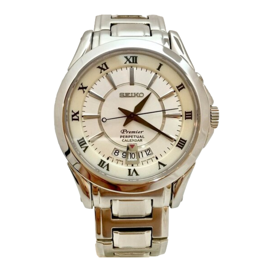
- Page 1 PARTS CATALOGUE / TECHNICAL GUIDE Cal. 6A32A SEIKO Brand Cal. No. 6A32A Movement Outside diameter Ø 27.8 Movement size (mm) Casing diameter Ø 27.3 Including Height 3.69 battery portion Time indication 3 hands (hour, minute and second hands) Step motor (hour, minute and second hands)
- Page 2 Cal. 6A32A PARTS CATALOGUE ● Order of disassembly for the hands, dial and wheels on the back side HOUR, MINUTE AND SECOND HANDS DIAL DATE DIAL GUARD 0808 051 DATE DIAL INTERMEDIATE 24-HOUR WHEEL 0817 046 24-HOUR WHEEL 1019 001 HOUR WHEEL 0273 031 (for models of the medium hand installation...
- Page 3 Cal. 6A32A PARTS CATALOGUE ● Order of disassembly for the battery, circuit block, wheels on the front side and switching mechanism 10 SILVER OXIDE BATTERY 11 POWER SWITCH SPRING SCREWS 0016 121 12 POWER SWITCH SPRING 4245 492 (for models of the medium hand installation height) 13 INSULATOR FOR CIRCUIT BLOCK...
- Page 4 Cal. 6A32A PARTS CATALOGUE [Parts list] There are different types of parts which are determined based on the case design or hand installation height. To choose the appropriate one, refer to “WATCH PARTS CATALOGUE CD-ROM.” Number PARTS CODE PARTS NAME REMARK of parts 0808 051...
- Page 5 Cal. 6A32A TECHNICAL GUIDE DISASSEMBLY Designated area of the setting stem 1. How to pull out the winding stem With the crown at the normal position, using a tool such as a pair of tweezers, press down the designated area indicated by “PUSH” (as shown in the illustration on the right) of the setting lever.
- Page 6 Cal. 6A32A TECHNICAL GUIDE Installation positions • Lubrication points • Remarks ❇ Make sure to lubricate the exact lubrication points with an adequate Reassembly (1) amount of the correct type of oil. Lubricate the main plate. normal quantity 1 Center pipe (AO-3) 2 Lower guide hole of the minute wheel and pinion (AO-3) 3 Guide pin of the train wheel setting...
- Page 7 Cal. 6A32A TECHNICAL GUIDE Installation positions • Lubrication points • Remarks ❇ Install the parts in the number order shown in the illustration below, Reassembly (2) paying attention to the following: Lubricate the switching mechanism. mounting positions, direction of mounting, type of oil, lubrication point(s) and amount of lubrication.
- Page 8 Cal. 6A32A TECHNICAL GUIDE Installation positions • Lubrication points • Remarks ❇ Install the parts in the number order shown in the illustration below, Reassembly (3) paying attention to the following: Reassemble the wheels and mounting positions, train wheel bridge. direction of mounting, type of oil, lubrication point(s) and amount of lubrication.
- Page 9 Cal. 6A32A TECHNICAL GUIDE 15 Train wheel setting lever 16 Fourth wheel and pinion (AO-3) 17 Train wheel bridge Positions of the guide pins for train wheel bridge When handling the plastic parts, use a pair of tweezers to securely hold them, paying attention not to damage the teeth or pinions.
- Page 10 Cal. 6A32A TECHNICAL GUIDE Installation positions • Lubrication points • Remarks ❇ Make sure to lubricate the exact lubrication points with an adequate Reassembly (4) amount of the correct type of oil. Lubricate the train wheel normal quantity bridge. 1 Minute wheel and pinion (AO-3) 2 Pin for crown switch (AO-3) 3 Upper pivot of the rotor (AO-2) 4 Upper pivot of the rotor (AO-2)
- Page 11 Cal. 6A32A TECHNICAL GUIDE Installation positions • Lubrication points • Remarks ❇ Install the parts in the number order shown in the illustration below, Reassembly (5) paying attention to the following: Reassemble the circuit block spacer and winding stem mounting positions, switch lever.
- Page 12 Cal. 6A32A TECHNICAL GUIDE Installation positions • Lubrication points • Remarks ❇ Install the parts in the number order shown in the illustration below, Reassembly (6) paying attention to the following: Reassemble the circuit block. mounting positions, direction of mounting. 1 Circuit block 2 Circuit block screw 3 Insulator for circuit block...
- Page 13 Cal. 6A32A TECHNICAL GUIDE Installation positions • Lubrication points • Remarks Reassembly (8) Reassemble the wheels on the back side 1 Intermediate date driving wheel C 2 Date driving wheel Pinion of the intermediate date driving wheel B 3 Hour wheel 4 24-hour wheel Refer to the Note 1 below.
- Page 14 Cal. 6A32A TECHNICAL GUIDE Installation positions • Lubrication points • Remarks ❇ Install the parts, paying attention to the following: Reassembly (9) mounting positions, Reassemble the date dial guard. direction of mounting. The date dial guard is fastened at the three positions (A, B and C) that are engaged with the date dial guard fixing guards and guide pins of the main plate.
- Page 15 Cal. 6A32A TECHNICAL GUIDE VALUE CHECKING ● Coil block resistance 1.28 - 1.48kW [Measuring the coil block resistance] 1. Measure the resistance with the coil block installed on the main plate. 2. Apply the red and black probes of the tester to the patterns of the coil lead terminal. While doing so, take care not to touch the end portion of the coil lead terminal, as this may break the coil wire.
- Page 16 Cal. 6A32A TECHNICAL GUIDE Installation positions • Lubrication points • Remarks Reassembling the exterior parts (1) Set the battery. Clip of the battery holder 1. Slide the battery in the direction shown by the arrow in the illustration (with the positive side facing up.) 2.
- Page 17 Cal. 6A32A TECHNICAL GUIDE How to set the minute hand 1. Temporarily set the minute hand pointing to the 12 o’clock position. 2. Turn the crown counterclockwise at the second click position to move the minute hand backward passing the 9 o’clock position, and then turn the crown clockwise to move the minute hand forward in order to check the timing when the date changes.
- Page 18 Cal. 6A32A TECHNICAL GUIDE HOW TO INPUT THE CALENDAR DATA (1) Method of operation Illustration Notes and tips When fixing in the inner Set the inner frame. frame, take care so as not to touch the circuit pattern. AC pattern Reset the IC (Integrated circuit.) •...
- Page 19 Cal. 6A32A TECHNICAL GUIDE HOW TO INPUT THE CALENDAR DATA (2) Method of operation Illustration Notes and tips Initial position adjustment for the calendar (2) (Set the date dial to show the numeral “1”.) * Keep the crown at the first click position.
- Page 20 Cal. 6A32A TECHNICAL GUIDE HOW TO INPUT THE CALENDAR DATA (3) Method of operation Illustration Notes and tips Set the date. * Keep the crown at the first click position. 1. Press the button once. * The second hand will turn Rotating the crown clockwise counterclockwise and stop will move the date dial forward.
- Page 21 Cal. 6A32A TECHNICAL GUIDE HOW TO INPUT THE CALENDAR DATA (4) Method of operation Illustration Notes and tips • Rapidly turning the crown 3. At the moment when the continuously will trigger the month numeral you wish to self-propelling movement set appears in the calendar of the date dial.
- Page 22 Cal. 6A32A TECHNICAL GUIDE HOW TO INPUT THE CALENDAR DATA (5) Method of operation Illustration Notes and tips * I f t h e w a t c h i s l e f t unoperated in this mode, the setting mode will be automatically cancelled and the watch will return to the normal mode within 2 to 3...
- Page 23 Cal. 6A32A TECHNICAL GUIDE HOW TO CHECK THE CALENDAR SETTINGS (1) Method of operation Illustration How to check the initial setting position of the calendar (1) To verify the second hand pointing to the “12 o’clock position” 1. Pull out the crown to the first click position. Hold down the button for 2 seconds or longer.
- Page 24 Cal. 6A32A TECHNICAL GUIDE HOW TO CHECK THE CALENDAR SETTINGS (2) Method of operation Illustration How to check the initial position of the month numeral * Keep the crown at the first click position. 1. Press the button once. • The second hand will rapidly move forward and stop pointing to the 10 o’clock position.