Table of Contents
Advertisement
UNISAW
®
10" Left Tilting Arbor Saw
(Model 36-953)
PART NO. 422-40-651-0013 - 01-24-05
Copyright © 2005 Delta Machinery
To learn more about DELTA MACHINERY
visit our website at: www.deltamachinery.com.
For Parts, Service, Warranty or other Assistance,
1-800-223-7278 (
1-800-463-3582).
please call
In Canada call
Advertisement
Table of Contents

Related Manuals for Delta UNISAW 36-953


Summary of Contents for Delta UNISAW 36-953
- Page 1 ® 10" Left Tilting Arbor Saw (Model 36-953) PART NO. 422-40-651-0013 - 01-24-05 Copyright © 2005 Delta Machinery To learn more about DELTA MACHINERY visit our website at: www.deltamachinery.com. For Parts, Service, Warranty or other Assistance, 1-800-223-7278 ( 1-800-463-3582). please call...
-
Page 2: Table Of Contents
NOT be modified and/or used for any application other than for which it was designed. If you have any questions relative to its application DO NOT use the product until you have written Delta Machinery and we have advised you. -
Page 3: Safety Guidelines
SAFETY GUIDELINES - DEFINITIONS It is important for you to read and understand this manual. The information it contains relates to protecting YOUR SAFETY and PREVENTING PROBLEMS. The symbols below are used to help you recognize this information. Indicates an imminently hazardous situation which, if not avoided, will result in death or serious injury. Indicates a potentially hazardous situation which, if not avoided, could result in death or serious injury. -
Page 4: General Safety Rules
13. USE RECOMMENDED ACCESSORIES. The use of accessories and attachments not recommended by IMPORTANT SAFETY INSTRUCTIONS Delta may cause damage to the machine or injury to the user. 14. USE THE PROPER EXTENSION CORD. Make sure your extension cord is in good condition. When using an extension cord, be sure to use one heavy enough to PROTECTION. -
Page 5: Additional Safety Rules For Table Saws
15. NEVER have any part of your body in line with the path of the saw blade. 16. NEVER REACH AROUND or over the saw blade. 17. NEVER attempt to free a stalled saw blade without first turning the machine “OFF”. 18. PROPERLY SUPPORT LONG OR WIDE workpieces. -
Page 6: Power Connections
POWER CONNECTIONS A separate electrical circuit should be used for your machines. This circuit should not be less than #12 wire and should be protected with a 20 Amp time lag fuse. If an extension cord is used, use only 3-wire extension cords which have 3- prong grounding type plugs and matching receptacle which will accept the machine’s plug. -
Page 7: Extension Cords
3. Permanently connected machines: If the machine is intended to be permanently connected, all wiring mentioned below must be done by a qualified electrician and conform to the National Electric Code and all local codes and ordinances. * THREE PHASE OPERATION: Three phase machines are not supplied with a power cord and must be permanently connected to a building’s electrical system. -
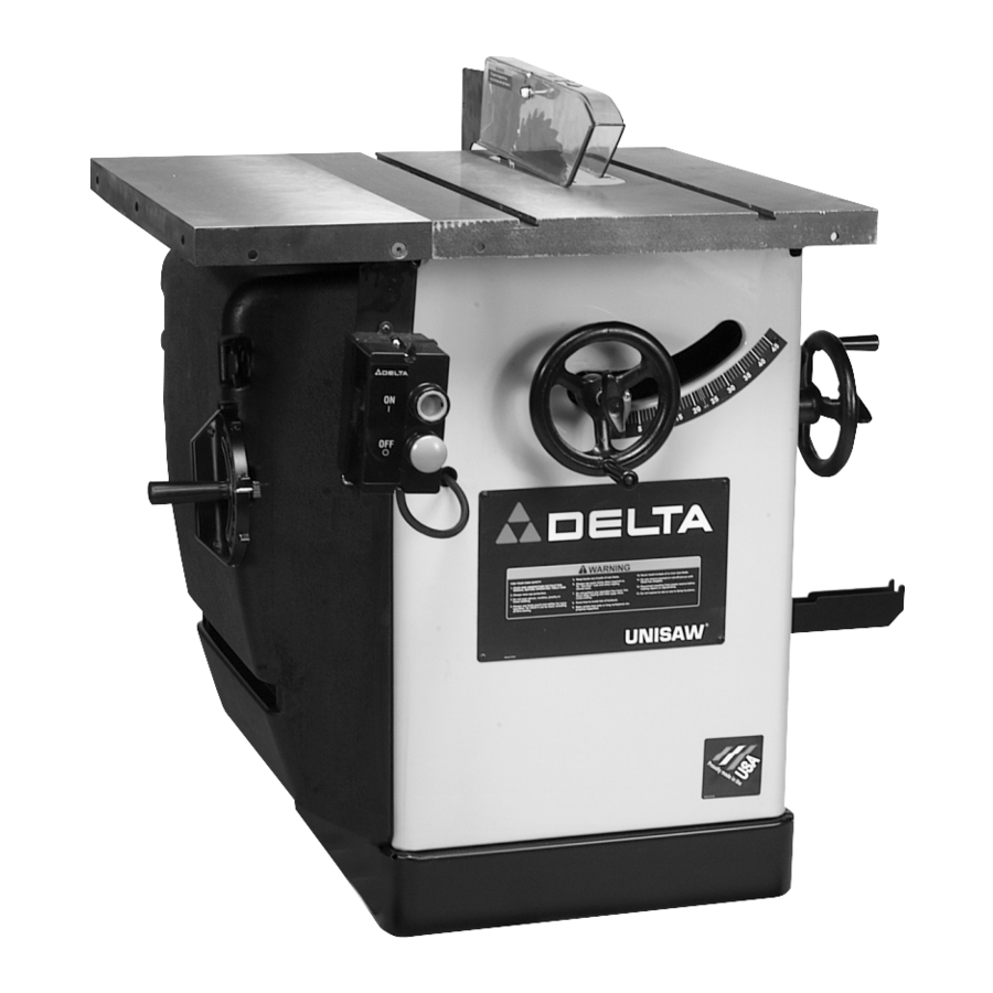
Page 8: Functional Description
FUNCTIONAL DESCRIPTION FOREWORD The Delta Unisaw is a 10" left tilting arbor saw. The maximum depth of cut at 90 degrees is 3 is 2 ” (54 mm). NOTICE: THE PHOTO ON THE MANUAL COVER ILLUSTRATES THE CURRENT PRODUCTION MODEL. ALL OTHER ILLUSTRATIONS CONTAINED... -
Page 9: Assembly
REMOVE THE STYROFOAM PACKING AND ANY OTHER LOOSE ITEMS FROM THE INSIDE OF THE SAW CABINET. IMPORTANT: The saw is shipped with the saw arbor in the 45 degree position. NOTE: THE HAND WHEEL MUST BE ASSEMBLED TO THE SAW, SEE THE SECTION “ASSEMBLING BLADE TILTING MECHANISM”, THEN PROCEED WITH THE FOLLOWING. - Page 10 Assemble left extension wing (A) Fig. 5 to the saw table. Align the three holes in the extension wing with the three holes in the side of the saw table. Place a 7/16" flat washer on a 7/16-20x1-1/4” hex head screw. Insert the screw through the hole in the extension wing and thread the screw into the tapped hole in the side of the table.
- Page 11 1. Place a 1/4" lockwasher then a 1/4" flat washer onto a 1/4-20x1/2" hex head screw. From the inside rear of the saw cabinet, insert the 1/4-20 x 1/2" hex head screw into the hole (B) Fig. 7, in the cabinet. Repeat this process for the two remaining screws.
- Page 12 (E) on screw and secure with a 5/16" hex nut (F). 3. Attach the side of switch bracket (A) Fig. 13, to the inside of extension wing at the front of the saw using the 7/16-20x1-1/4" screw (C) and 7/16" flat washer. Tighten screws (C) and (D) securely.
- Page 13 (C), which were removed in STEP 2. 5. Insert threaded end of support rod (G) Fig. 18, through slot in rear of saw and into hole in rear trunnion (H). Fasten support rod (G) to trunnion with star washer and 5/8-18 hex jam nut (J) Fig. 19. NOTE: Thread nut (J) Fig.
- Page 14 11. Reassemble the saw blade, making certain the teeth are pointing down at the front of the saw table as shown in Fig. 26, and assemble the outside blade flange and arbor nut (X). With open end wrench (Y) on the flats of the arbor to keep it from turning, tighten arbor nut by turning box end wrench (Z) clockwise.
- Page 15 Fig. 28 splitter (P) is aligned with the saw blade (B). Using a square (C) Figs. 28 and 29, make certain saw blade (B) Fig. 28, and splitter (P) Fig. 29, are 90 degrees to the table surface. Once you are certain the splitter is aligned to the saw blade and table, tighten all splitter mounting hardware (D) Fig.
- Page 16 HOLDER BRACKETS Assemble the rip fence holder brackets (A) and (B) Fig. 37, to the four holes located in the right hand side of the saw cabinet using four #10 x 1/2" sheet metal screws supplied. ASSEMBLING DUST CHUTE ADAPTER The Unisaw is supplied with a dust chute connector to provide a means of connecting a 4"...
-
Page 17: Operation
(A), clockwise. To lower the saw blade, turn handwheel (A) counterclockwise. The saw blade is locked at any height by turning the lock knob (B) Fig. 41, clockwise. Due to the wedge action of this locking device, only a small amount of force is required to lock the blade raising mechanism securely. -
Page 18: Adjusting 90 And 45 Degree Positive Stops
5. Tighten the four screws that were loosened in STEP 4. 6. Tilt the blade to 45 degrees, and turn the saw blade by hand, and insure it does not contact the table insert. - Page 19 ADJUSTING TABLE INSERT Place a straight edge (B) across the table at both ends of the table insert as shown in Fig. 46. The table insert (A) should always be level with the table. If an adjustment is necessary, turn the adjusting screws (C), as needed, with allen wrench supplied.
-
Page 20: Changing The Blade
2. Place a block of wood (C) Fig. 51, between the motor and saw cabinet as shown. NOTE: It may be necessary to raise the saw arbor in order to insert the wooden block. Lower the saw arbor until the motor contacts the wood. - Page 21 The following information describes the safe and proper method for performing the most common sawing operations. THE USE OF ATTACHMENTS AND ACCESSORIES NOT RECOMMENDED BY DELTA MAY RESULT IN THE RISK OF INJURY TO THE USER OR OTHERS.
- Page 22 Since the work is pushed along the fence, it must have a straight edge and make solid contact with the table. THE SAW BLADE GUARD MUST BE USED. ON DELTA SAWS, THE GUARD HAS ANTI- KICKBACK FINGERS TO PREVENT KICKBACK AND A SPLITTER TO PREVENT THE WOOD KERF FROM CLOSING AND BINDING THE BLADE.
- Page 23 When ripping boards longer than three feet, use a work support at the rear of the saw to keep the workpiece from falling off the saw table. 3. If the ripped work is less than 6 inches wide, a push stick should always be used to complete the feed, as shown in Fig.
- Page 24 1 inch facing. 3. Position the wood-facing over the cutterhead with the cutterhead below the surface of the table. Turn the saw on and raise the cutterhead. The cutterhead will cut its own groove in the wood-facing. Fig. 68 shows a typical moulding operation.
- Page 25 2. Attach the dado head set (D) Fig. 72, to the saw arbor. NOTE: THE OUTSIDE ARBOR FLANGE CAN NOT BE USED WITH THE DADO HEAD SET, TIGHTEN THE ARBOR NUT AGAINST THE DADO HEAD SET BODY.
-
Page 26: Constructing A Featherboard
3. Fig. 73, shows a typical dado operation using the miter gage as a guide. NEVER USE THE DADO HEAD IN A BEVEL POSITION. ALWAYS INSTALL BLADE GUARD AFTER OPERATION IS COMPLETED. Fig. 73 CONSTRUCTING A FEATHERBOARD Fig. 74, illustrates dimensions for making a typical featherboard. The material which the featherboard is constructed of, should be a straight piece of wood that is free of knots and cracks. -
Page 27: Constructing A Push Stick
CONSTRUCTING A PUSH STICK When ripping work less than 4 inches wide, a push stick should be used to complete the feed and could easily be made from scrap material by following the pattern shown. -
Page 28: Troubleshooting
Also, check for blown fuses or open circuit breakers in the line. PARTS, SERVICE OR WARRANTY ASSISTANCE All Delta Machines and accessories are manufactured to high quality standards and are serviced by a network • of Porter-Cable Delta Factory Service Centers and Delta Authorized Service Stations. To obtain additional information regarding your Delta quality product or to obtain parts, service, warranty assistance, or the location of the nearest service outlet, please call 1-800-223-7278 (In Canada call 1-800-463-3582). -
Page 29: Accessories
A complete line of accessories is available from your Delta Supplier, Porter-Cable • Delta Factory Service Centers, and Delta Authorized Service Stations. Please visit our Web Site for the name of your nearest supplier. Since accessories other than those offered by Delta have not been tested with this product, use of such accessories could be hazardous. -
Page 30: Warranty
Two Year Limited New Product Warranty Delta will repair or replace, at its expense and at its option, any new Delta machine, machine part, or machine accessory which in normal use has proven to be defective in workmanship or material, provided that the customer returns the product prepaid to a Delta factory service center or authorized service station with proof of purchase of the product within two years and provides Delta with reasonable opportunity to verify the alleged defect by inspection. - Page 31 NOTES...
- Page 32 Phone: (604) 420-0102 Fax: (604) 420-3522 The following are trademarks of PORTER-CABLE • DELTA (Las siguientes son marcas registradas de PORTER-CABLE • DELTA S.A.) (Les marques suivantes sont des marques de fabriquant de la PORTER-CABLE • DELTA): Auto-Set Contractor’s Saw II™, Delta ®...