Table of Contents
Advertisement
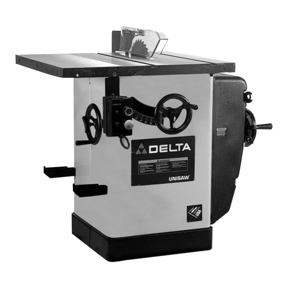
UNISAW
®
10" Right Tilting Arbor Saw
(Models 34-801, 34-806, 34-814, 36-812)
PART NO. 422-04-651-0064 (01-15-02)
Copyright © 2002 Delta Machinery
To learn more about DELTA MACHINERY
visit our website at: www.deltamachinery.com.
For Parts, Service, Warranty or other Assistance,
1-800-223-7278 (
1-800-463-3582).
please call
In Canada call
Advertisement
Table of Contents

Related Manuals for Delta UNISAW 34-801


Summary of Contents for Delta UNISAW 34-801
- Page 1 UNISAW ® 10" Right Tilting Arbor Saw (Models 34-801, 34-806, 34-814, 36-812) PART NO. 422-04-651-0064 (01-15-02) Copyright © 2002 Delta Machinery To learn more about DELTA MACHINERY visit our website at: www.deltamachinery.com. For Parts, Service, Warranty or other Assistance, 1-800-223-7278 ( 1-800-463-3582).
-
Page 2: General Safety Rules
If you have any questions relative to a particular application, DO NOT use the machine until you have first contacted Delta to determine if it can or should be performed on the product. -
Page 3: Additional Safety Rules For Circular Saws
ADDITIONAL SAFETY RULES FOR CIRCULAR SAWS WARNING: FAILURE TO FOLLOW THESE RULES MAY RESULT IN SERIOUS PERSONAL INJURY 1. DO NOT OPERATE THIS MACHINE until it is 10. NEVER run the workpiece between the fence and a assembled and installed according to the moulding cutterhead. -
Page 4: Power Connections
POWER CONNECTIONS A separate electrical circuit should be used for your machines. This circuit should not be less than #12 wire and should be protected with a 20 Amp time lag fuse. If an extension cord is used, use only 3-wire extension cords which have 3- prong grounding type plugs and matching receptacle which will accept the machine’s plug. -
Page 5: Three Phase Operation
FIVE HORSEPOWER MOTORS The motors supplied with single phase, 5 horsepower Unisaws are designed to be operated from a 220-240 volt power system. The 5 horsepower Unisaws are not supplied with a power cord. They must be permanently connected to the building electrical system and grounded according to the National Electrical Code. -
Page 6: Unpacking And Cleaning
OPERATING INSTRUCTIONS FOREWORD The Delta Unisaw is a 10" right tilting arbor saw. The Delta Unisaw features set the standards in the table saw industry. UNPACKING AND CLEANING Carefully unpack the machine and all loose items from the shipping container(s). Remove the protective coating from all unpainted surfaces. -
Page 7: Assembly Instructions
ASSEMBLY INSTRUCTIONS WARNING: FOR YOUR OWN SAFETY, DO NOT CONNECT THE SAW TO THE POWER SOURCE UNTIL THE SAW IS COMPLETELY ASSEMBLED AND YOU UNDERSTAND THE ENTIRE INSTRUCTION MANUAL. ASSEMBLING BLADE TILTING MECHANISM HANDLE 1. Install fiber washer (A) Fig. 3, on the blade tilting mechanism shaft (B). - Page 8 ASSEMBLING LVC STARTER BOX TO CABINET If you purchased the machine with magnetic push button electrical controls, the saw is shipped with the starter box completely wired to the switch and motor. However, the starter box must be mounted to the saw cabinet.
-
Page 9: Assembling Blade Guard And Splitter Assembly
Fig. 11 Fig. 12 ASSEMBLING GPE ON/OFF SWITCH 1. The GPE on/off switch (A) Fig. 11, is shipped attached to a mounting bracket at the right side of the machine. 2. Loosely assemble switch and switch bracket (A) Fig. 12, to the inside front lip of extension table with 5/16- 18x1"... - Page 10 Fig. 16 Fig. 17 4. If an adjustment is necessary, loosen two screws (F) Fig. 17, and adjust splitter bracket (A) until it is aligned with the inside blade flange (B) Fig. 15. Tighten two screws (F). Loosely assemble screw and fastener plate (C), which were removed in STEP 3.
- Page 11 Fig. 23 Fig. 22 8. Assemble upper splitter bracket (M) Fig. 22, to lower bracket (L) using a 5/16-18x1" hex head screw (N) with 5/16" lockwasher and 5/16" flat washer. NOTE: Do not tighten screw (N) at this time. 9. Insert the front end of splitter (P) Fig. 23, inside the splitter mounting bracket behind splitter fastener plate and screw (C).
- Page 12 Fig. 28 Fig. 29 12. Using a straight edge (A) Fig. 27, make certain the splitter (P) is aligned with the saw blade (B). Using a square (C) Figs. 28 and 29, make certain saw blade (B) Fig. 28, and splitter (P) Fig. 29, are 90 degrees to the table surface.
- Page 13 2. Place the motor cover (A) in the opening of the Unisaw as shown in Fig. 35. Place the rear motor cover clips inside the motor opening and push the front of the motor cover until all 4 motor cover clips are engaged with the motor cover opening in the Unisaw.
-
Page 14: Starting And Stopping The Saw
IMPORTANT: When the machine is not in use, the switch should be locked in the “OFF” position using a padlock (A) Fig. 40, (Delta Cat. No. 50-325), with a 3/16" diameter Fig. 39 shackle to prevent unauthorized use. NOTE: GPE switch shown. -
Page 15: Adjusting Table
ADJUSTING 90 AND 45 DEGREE POSITIVE STOPS Positive stops are provided to quickly and accurately position the blade at 90 and 45 degrees to the table. To check and adjust the positive stops, proceed as follows: DISCONNECT MACHINE FROM POWER SOURCE. 1. -
Page 16: Adjusting Table Insert
ADJUSTING TABLE INSERT Place a straight edge (B) across the table at both ends of the table insert as shown in Fig. 46. The table insert (A) should always be level with the table. If an adjustment is necessary, turn the adjusting screws (C), as needed, with allen wrench supplied. -
Page 17: Maintenance
MAINTENANCE CHANGING THE SAW BLADE 1. DISCONNECT MACHINE FROM POWER SOURCE. 2. NOTE: Two wrenches are supplied with the saw for changing the saw blade; a box end wrench and open end wrench. 3. Remove table insert and raise saw blade to its maximum height. - Page 18 The following information describes the safe and proper method for performing the most common sawing operations. NOTE: THE USE OF ATTACHMENTS AND ACCESSORIES NOT RECOMMENDED BY DELTA MAY RESULT IN THE RISK OF INJURY TO PERSONS.
-
Page 19: Using The Fence As Acut-Off Gage
Fig. 56 Fig. 57 USING THE FENCE AS A CUT-OFF GAGE WARNING: WHEN USING YOUR UNIFENCE AS A CUT-OFF GAGE, MAKE SURE IT IS PROPERLY SET UP AS DESCRIBED HERE. The fence can be used as a cut-off gage when cross cutting a number of pieces to the same length. -
Page 20: Using Auxiliary Wood Facing On The Unifence
When ripping boards longer than three feet, it is recommended that a work support be used at the rear of the saw to keep the workpiece from falling off the saw table. If the ripped work is less than 4 inches wide, a push stick should always be used to complete the feed, as shown in Fig. - Page 21 IMPORTANT: For certain cutting operations such as dadoing and moulding where you are not cutting completely through the workpiece, the blade guard and splitter assembly cannot be used. Loosen screws (G) and (H) Fig. 65. Lift up and swing blade guard and splitter assembly (W) Fig.
-
Page 22: Using Accessory Dado Head
USING ACCESSORY DADO HEAD IMPORTANT: THE BLADE GUARD AND SPLITTER ASSEMBLY CANNOT BE USED WHEN DADOING OR MOULDING AND MUST BE REMOVED OR SWUNG TO THE REAR OF THE SAW. Dadoing is cutting a rabbet or wide groove into the work. Most dado head sets are made up of two outside saws and four or five inside cutters, as shown in Fig. -
Page 23: Constructing A Featherboard
CONSTRUCTING A FEATHERBOARD Fig. 74, illustrates dimensions for making a typical featherboard. The material which the featherboard is constructed of, should be a straight piece of wood that is free of knots and cracks. Featherboards are used to keep the work in contact with the fence and table and help prevent kickbacks. -
Page 24: Constructing A Push Stick
CONSTRUCTING A PUSH STICK When ripping work less than 4 inches wide, a push stick should be used to complete the feed and could easily be made from scrap material by following the pattern shown. - Page 25 Splitter and Anti-kickback Fingers Fig. 77, is an accessory that can be used in place of the standard blade guard that is supplied with the Unisaw. The Delta Model 34-976 Uniguard Blade Guard can be mounted to the Unisaw, the Unisaw with a Jet-Lock rip fence, the Unisaw with a 52"...
- Page 26 Two Year Limited Warranty Delta will repair or replace, at its expense and at its option, any Delta machine, machine part, or machine accessory which in normal use has proven to be defective in workmanship or material, provided that the customer returns the product prepaid to a Delta factory service center or authorized service station with proof of purchase of the product within two years and provides Delta with reasonable opportunity to verify the alleged defect by inspection.
- Page 27 NOTES...
- Page 28 Parts and accessories for Porter-Cable ·Delta products should be obtained by contacting any Porter-Cable·Delta Distributor, Authorized Service Center, or Porter-Cable·Delta Factory Service Center. If you do not have access to any of these, call 800-223-7278 and you will be directed to the nearest Porter-Cable·Delta Factory Service Center. Las Estaciones de Servicio Autorizadas están ubicadas en muchas grandes ciudades.