Table of Contents
Advertisement
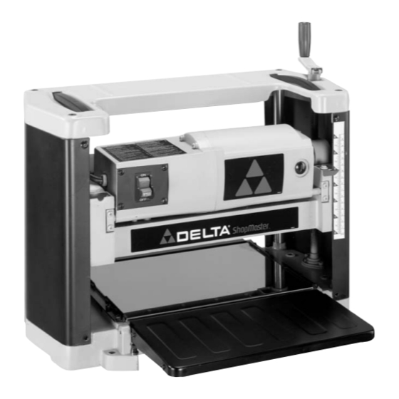
12" Portable Planer
(Model TP300)
PART NO. 909543 - 01-02-03
Copyright © 2003 Delta Machinery
To learn more about DELTA MACHINERY
ESPAÑOL: PÁGINA 17
visit our website at: www.deltamachinery.com.
For Parts, Service, Warranty or other Assistance,
1-800-223-7278 (
1-800-463-3582).
please call
In Canada call
Advertisement
Table of Contents

Related Manuals for Delta TP300


Summary of Contents for Delta TP300
- Page 1 12" Portable Planer (Model TP300) PART NO. 909543 - 01-02-03 Copyright © 2003 Delta Machinery To learn more about DELTA MACHINERY ESPAÑOL: PÁGINA 17 visit our website at: www.deltamachinery.com. For Parts, Service, Warranty or other Assistance, 1-800-223-7278 ( 1-800-463-3582). please call...
-
Page 2: Safety Guidelines - Definitions
If you have any questions rela- tive to a particular application, DO NOT use the machine until you have first contacted Delta to determine if it can or should be performed on the product. - Page 3 17. REDUCE THE RISK OF UNINTENTIONAL STARTING. 21. NEVER LEAVE TOOL RUNNING UNATTENDED. Make sure switch is in “OFF” position before plugging in TURN POWER OFF. Don’t leave tool until it comes to a power cord. In the event of a power failure, move switch complete stop.
-
Page 4: Power Connections
POWER CONNECTIONS A separate electrical circuit should be used for your machines. This circuit should not be less than #12 wire and should be protected with a 20 Amp time lag fuse. If an extension cord is used, use only 3-wire extension cords which have 3- prong grounding type plugs and matching receptacle which will accept the machine’s plug. -
Page 5: Extension Cords
OPERATING INSTRUCTIONS FOREWORD Delta ShopMaster Model TP300 is a 12" (305mm) Portable Planer. It has the following cutting capacity; 12" (305mm) width , 6" (152mm) thickness and 3/32" (2.4mm) depth of cut. Features include; basic machine with powerful 15 amp, 120 volt motor, dust chute, two-knife cutterhead with a set of high-speed steel double-edged reversible knives;... - Page 6 PLANER PARTS 1 - 12" Planer 2 - Chip Deflector Fig. 2 3 - Knife Setting Gage 4 - 8mm and 10mm Open-End Wrench 5 - M5 x 20mm Hex Socket Head Screw 6 - M5 Wing Nut (2) 7 - M5 Flat Washer (2) 8 - Elevating Handle Fig.
- Page 7 ASSEMBLY RAISING AND LOWERING HANDLE 1. Assemble raising and lowering handle (A) Fig. 4, to shaft (B) and fasten in place with M5x20mm screw (C). NOTE: Make certain the flats of the handle and flat on shaft are aligned with each other. Fig.
-
Page 8: Chip Deflector
CHIP DEFLECTOR 1. Assemble chip deflector (A) Fig. 7, to the planer by inserting end of chip deflector over the top of the cutter- head. Make certain the two screws, one of which is shown at (B) are inserted upward through the two slots (C) in the chip deflector. -
Page 9: Operating Controls And Adjustments
OPERATING CONTROLS AND ADJUSTMENTS STARTING AND STOPPING PLANER The “ON/OFF” switch (A) Fig. 13, is located on the front of the planer motor. To turn the machine “ON”, move the switch toggle (B) up to the “ON” position. To turn the switch “OFF”, move the switch toggle (B) down to the “OFF”... -
Page 10: Storing The Power Cord
LEVELING EXTENSION TABLES For optimum performance, the extension tables, one of which is shown at (A) Fig. 17, must be level with the planer table. To check the extension tables and adjust if necessary, proceed as follows: 1. Place a straight edge (B) Fig. 17, on the planer table (A) with one end extending out over the extension table as shown. -
Page 11: Replacing And Resetting Knives
Fig. 21 Fig. 22 4. If an adjustment to one or both knives is necessary, slightly loosen the seven locking screws, six of which are shown at (C) Fig. 21, by turning the screws CLOCKWISE into the knife locking bar just enough to relieve stress in the cutterhead and not disturb the knife setting. -
Page 12: Lifting Straps
LIFTING STRAPS Your planer is provided with two lifting straps (A) Fig. 23, located on the top of the planer, for ease in transporting the planer. Fig. 23 OPERATING HINTS When using your machine, you may want to follow these few simple steps for achieving the best results possible. 1. -
Page 13: Maintenance
MAINTENANCE BRUSH INSPECTION AND REPLACEMENT DISCONNECT MACHINE FROM POWER SOURCE. Brush life varies. It depends on the load on the motor. Check the brushes after the first 50 hours of use for a new machine or after a new set of brushes has been installed. - Page 14 NOTES...
- Page 15 NOTES...
-
Page 16: Parts, Service Or Warranty Assistance
Two Year Limited Warranty Delta will repair or replace, at its expense and at its option, any Delta machine, machine part, or machine accessory which in normal use has proven to be defective in workmanship or material, provided that the customer returns the product pre- paid to a Delta factory service center or authorized service station with proof of purchase of the product within two years and provides Delta with reasonable opportunity to verify the alleged defect by inspection. - Page 17 Delta Distributor, Authorized · Service Center, or Porter-Cable Delta Factory Service Center. If you do not have access to any of these, call 800-223-7278 and you will · be directed to the nearest Porter-Cable Delta Factory Service Center. Las Estaciones de Servicio Autorizadas están ubicadas en muchas grandes ciudades.