Table of Contents
Advertisement
Quick Links
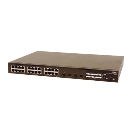
TigerSwitch 10/100/1000
Gigabit Ethernet Switch
◆ 24 auto-MDI/MDI-X 10/100/1000BASE-T ports
◆ 4 ports shared with 4 SFP transceiver slots
◆ Non-blocking switching architecture
◆ Support for a redundant power unit
◆ Spanning Tree Protocol
◆ Up to six LACP or static 4-port trunks
◆ Layer 2/3/4 CoS support through four priority queues
◆ Full support for VLANs with GVRP
◆ IGMP multicast filtering and snooping
◆ Support for jumbo frames up to 9 KB
◆ Manageable via console, Web, SNMP/RMON
Management Guide
SMC8624T
Advertisement
Table of Contents

Related Manuals for SMC Networks 8624T - annexe 1


Summary of Contents for SMC Networks 8624T - annexe 1
-
Page 1: Management Guide
TigerSwitch 10/100/1000 Gigabit Ethernet Switch ◆ 24 auto-MDI/MDI-X 10/100/1000BASE-T ports ◆ 4 ports shared with 4 SFP transceiver slots ◆ Non-blocking switching architecture ◆ Support for a redundant power unit ◆ Spanning Tree Protocol ◆ Up to six LACP or static 4-port trunks ◆... - Page 3 TigerSwitch 10/100/1000 Management Guide From SMC’s Tiger line of feature-rich workgroup LAN solutions 38 Tesla Irvine, CA 92618 June 2002 Phone: (949) 679-8000 Pub. # 150200016900A...
- Page 4 Irvine, CA 92618 All rights reserved. Printed in Taiwan Trademarks: SMC is a registered trademark; and EZ Switch, TigerStack and TigerSwitch are trademarks of SMC Networks, Inc. Other product and company names are trademarks or registered trademarks of their respective holders.
- Page 5 All SMC products carry a standard 90-day limited warranty from the date of purchase from SMC or its Authorized Reseller. SMC may, at its own discretion, repair or replace any product not operating as warranted with a similar or functionally equivalent product, during the applicable warranty term.
- Page 6 RIGHTS, WHICH MAY VARY FROM STATE TO STATE. NOTHING IN THIS WARRANTY SHALL BE TAKEN TO AFFECT YOUR STATUTORY RIGHTS. * SMC will provide warranty service for one year following discontinuance from the active SMC price list. Under the limited lifetime warranty, internal and external power supplies, fans, and cables are covered by a standard one-year warranty from date of purchase.
-
Page 7: Table Of Contents
ONTENTS Switch Management ......1-1 Connecting to the Switch ........1-1 Configuration Options . - Page 8 ONTENTS Configuring Interface Connections ..... . 2-26 Setting Broadcast Storm Thresholds ..... 2-28 Configuring Port Mirroring .
- Page 9 ONTENTS Interfaces Attached to a Multicast Router ....2-72 Displaying Port Members of Multicast Services ... . 2-75 Adding Multicast Addresses to VLANs .
- Page 10 ONTENTS boot system ......... 3-23 System Management Commands .
- Page 11 ONTENTS show ip redirects ........3-55 ping .
- Page 12 ONTENTS bridge priority ........3-88 bridge-group path-cost .
- Page 13 ONTENTS switchport priority default ......3-122 queue bandwidth ........3-123 queue cos-map .
- Page 14 ONTENTS PPENDICES Troubleshooting ......A-1 Troubleshooting Chart ........A-1 Upgrading Firmware via the Serial Port .
-
Page 15: Switch Management
Management Protocol). This SNMP agent permits the switch to be managed from any system in the network using management software, such as such as SMC’s free EliteView software. The CLI program can be accessed by a direct connection to the RS-232 serial console port on the switch, or remotely by a Telnet connection over the network. - Page 16 WITCH ANAGEMENT The switch’s CLI configuration program, Web interface, and SNMP agent allow you to perform the following management functions: • Set user names and passwords for up to 16 users • Set an IP interface for a management VLAN •...
-
Page 17: Required Connections
ONNECTING TO THE WITCH Required Connections The switch provides an RS-232 serial port that enables a connection to a PC or terminal for monitoring and configuring the switch. A null-modem console cable is provided with the switch. Attach a VT100-compatible terminal, or a PC running a terminal emulation program to the switch. -
Page 18: Remote Connections
WITCH ANAGEMENT 4. Once you have set up the terminal correctly, the console login screen will be displayed. Note: Refer to “Line Commands” on page 3-57 for a complete description of console configuration options. For a description of how to use the CLI, see “Using the Command Line Interface”... -
Page 19: Basic Configuration
ASIC ONFIGURATION Basic Configuration Console Connection The CLI program provides two different command levels — normal access level (Normal Exec) and privileged access level (Privileged Exec). The commands available at the Normal Exec level are a limited subset of those available at the Privileged Exec level and allow you to only display information and use basic utilities. -
Page 20: Setting An Ip Address
WITCH ANAGEMENT Passwords can consist of up to eight alphanumeric characters and are case sensitive. To prevent unauthorized access to the switch, set the passwords as follows: 1. Open the console interface with the default user name and password “admin” to access the Privileged Exec level. 2. -
Page 21: Manual Configuration
ASIC ONFIGURATION Note: Only one VLAN interface can be assigned an IP address (the default is VLAN 1). This defines the management VLAN, the only VLAN through which you can gain management access to the switch. If you assign an IP address to any other VLAN, the new IP address overrides the original IP address and this becomes the new management VLAN. -
Page 22: Dynamic Configuration
WITCH ANAGEMENT 4. To set the IP address of the default gateway for the network to which the switch belongs, type “ip default-gateway gateway,” where “gateway” is the IP address of the default gateway. Press <Enter>. Console(config)#interface vlan 1 Console(config-if)#ip address 192.168.1.5 255.255.255.0 Console(config-if)#exit Console(config)#ip default-gateway 192.168.1.254 Console(config)#... -
Page 23: Enabling Snmp Management Access
ASIC ONFIGURATION 3. Type “exit” to return to the global configuration mode. Press <Enter>. 4. Type “ip dhcp restart” to begin broadcasting service requests. Press <Enter>. 5. Wait a few minutes, and then check the IP configuration settings, by typing the “show ip interface” command. Press <Enter>. 6. -
Page 24: Community Strings
“mode” is rw (read/write) or ro (read only). Press <Enter>. 2. To remove an existing string, simply type “no snmp-server community string,” where “string” is the community access string to remove. Press <Enter>. Console(config)#snmp-server community smc rw Console(config)#snmp-server community private Console(config)# 1-10... -
Page 25: Saving Configuration Settings
ASIC ONFIGURATION Trap Receivers You can also specify SNMP stations that are to receive traps from the switch. To configure a trap receiver, complete the following steps: 1. From the Privileged Exec level global configuration mode prompt, type “snmp-server host host-address community-string,” where “host-address”... -
Page 26: Managing System Files
WITCH ANAGEMENT Managing System Files The switch’s flash memory supports three types of system files that can be managed by the CLI program, Web interface, or SNMP. The switch’s file system allows files to be uploaded and downloaded, copied, deleted, and set as a start-up file. -
Page 27: System Defaults
YSTEM EFAULTS System Defaults The switch’s system defaults are provided in the configuration file “Factory_Default_Config.cfg.” To reset the switch defaults, this file should be set as the startup configuration file. See “Setting the Startup Configuration File” on page 2-19. The following table lists some of the basic system defaults. Function Parameter Default... - Page 28 WITCH ANAGEMENT Function Parameter Default Console Port Baud Rate 9600 Connection Data bits Stop bits Parity none Local Console Timeout 0 (disabled) Port Status Admin Status Enabled Auto-negotiation Enabled Flow Control Disabled 10/100/1000 Mbps Port 10 Mbps half duplex Capability 10 Mbps full duplex 100 Mbps half duplex 100 Mbps full duplex...
- Page 29 YSTEM EFAULTS Function Parameter Default Class of Service Ingress Port Priority Weighted Round Robin Class 0: 16 Class 1: 64 Class 2: 128 Class 3: 240 IP Precedence Priority Disabled IP DSCP Priority Disabled Multicast Filtering IGMP Snooping Enabled Act as Querier Enabled Broadcast Storm Status...
- Page 30 WITCH ANAGEMENT 1-16...
-
Page 31: Configuring The Switch
HAPTER ONFIGURING THE WITCH Using the Web Interface This switch provides an embedded HTTP Web agent. Using a Web browser you can configure the switch and view statistics to monitor network activity. The Web agent can be accessed by any computer on the network using a standard Web browser (Internet Explorer 5.0 or above, or Netscape Navigator 6.2 or above). -
Page 32: Navigating The Web Browser Interface
ONFIGURING THE WITCH 3. After you enter a user name and password, you will have access to the system configuration program. Notes: 1. You are allowed three attempts to enter the correct password; on the third failed attempt the current connection is terminated. -
Page 33: Configuration Options
AVIGATING THE ROWSER NTERFACE Configuration Options Configurable parameters have a dialog box or a drop-down list. Once a configuration change has been made on a page, be sure to click on the “Apply” or “Apply Changes” button to confirm the new setting. The following table summarizes the Web page configuration buttons. -
Page 34: Panel Display
ONFIGURING THE WITCH Notes: 1. To ensure proper screen refresh, be sure that Internet Explorer 5.x is configured as follows: Under the menu “Tools / Internet Options / General / Temporary Internet Files / Settings,” the setting for item “Check for newer versions of stored pages” should be “Every visit to the page.”... -
Page 35: Main Menu
Main Menu Using the onboard Web agent, you can define system parameters, manage and control the switch, and all its ports, or monitor network conditions. The following table briefly describes the selections available from this program. Menu Description Page System System Information Provides basic system description, including contact information... - Page 36 ONFIGURING THE WITCH Menu Description Page Address Table Static Addresses Displays entries for interface, address or VLAN 2-30 Dynamic Addresses Displays or edits static entries in the Address 2-31 Table Address Aging Sets timeout for dynamically learned entries 2-32 Spanning Tree STA Information Displays STA values used for the bridge 2-35...
- Page 37 Menu Description Page Priority Default Port Priority Sets the default priority for each port 2-54 Default Trunk Priority Sets the default priority for each trunk 2-54 Traffic Class Maps IEEE 802.1p priority tags to output 2-55 queues Queue Scheduling Configures Weighted Round Robin queueing 2-58 IP Precedence/DSCP Globally selects IP Precedence or DSCP...
-
Page 38: Basic Configuration
ONFIGURING THE WITCH Menu Description Page IGMP Member Indicates multicast addresses associated with the 2-75 Port Table selected VLAN Statistics Lists Ethernet and RMON port statistics 2-77 Basic Configuration Displaying System Information You can easily identify the system by providing a descriptive name, location and contact information. - Page 39 Console(config)#snmp-server location TPS - 3rd Floor 3-46 Console(config)#snmp-server contact Chris 3-45 Console#show system 3-37 System description: SMC TigerSwitch - SMC8624T System OID string: 1.3.6.1.4.1.202.20.24 System information System Up time: 0 days, 2 hours, 4 minutes, and 7.13 seconds System Name : SMC8624T Test Switch...
-
Page 40: Setting The Ip Address
ONFIGURING THE WITCH Setting the IP Address An IP address may be used for management access to the switch over your network. By default, the switch uses DHCP to assign IP settings to VLAN 1 on the switch. If you wish to manually configure IP settings, you need to change the switch’s user-specified defaults (IP address 0.0.0.0 and netmask 255.0.0.0) to values that are compatible with your network. - Page 41 ASIC ONFIGURATION • Subnet Mask – This mask identifies the host address bits used for routing to specific subnets. • Gateway IP Address – IP address of the gateway router between this device and management stations that exist on other network segments. •...
- Page 42 ONFIGURING THE WITCH Web – Click System/IP. Specify the Management VLAN, set the IP Address Mode to DHCP or BOOTP. Then click “Apply” to save your changes. The switch will broadcast a request for IP configuration settings on the next power reset. Otherwise, you can click “Restart DHCP” to immediately request a new address.
-
Page 43: Security
ECURITY Security Configuring the Logon Password The guest only has read access for most configuration parameters. However, the administrator has write access for parameters governing the onboard agent. You should therefore assign a new administrator password as soon as possible, and store it in a safe place. Notes: 1. -
Page 44: Configuring Radius Logon Authentication
ONFIGURING THE WITCH Configuring Radius Logon Authentication Remote Authentication Dial-in User Service (RADIUS) is an authentication protocol that uses a central server to control access to RADIUS-compliant devices on the network. A RADIUS server can be programmed with a database of multiple user name/password pairs and associated privilege levels for each user or group that requires management access to this switch using the console port, Telnet or the Web. -
Page 45: Cli Commands
ECURITY • Timeout for a reply – The number of seconds the switch waits for a reply from the RADIUS server before it resends the request. Note: The local switch user database has to be set up by manually entering user names and passwords using the CLI. Web –... -
Page 46: Managing Firmware
ONFIGURING THE WITCH Managing Firmware You can upload/download firmware to or from a TFTP server. By saving runtime code to a file on a TFTP server, that file can later be downloaded to the switch to restore operation. You can also set the switch to use new firmware without overwriting the previous version. - Page 47 ANAGING IRMWARE If you download specifying a new destination file name, be sure to select the new file from the drop-down box, and then click “Apply Changes.” To start the new firmware, reboot the system. CLI – Enter the IP address of the TFTP server, select “config” or “opcode”...
-
Page 48: Saving Or Restoring Configuration Settings
ONFIGURING THE WITCH Saving or Restoring Configuration Settings You can upload/download configuration settings to/from a TFTP server. The configuration file can be later downloaded to restore the switch’s settings. Command Attributes • Destination File Name — The destination configuration file name should not contain slashes (\ or /), the leading letter of the file name should not be a period (.), and the length of file name should be 1 to 31 characters. -
Page 49: Setting The Startup Configuration File
ANAGING IRMWARE CLI – Enter the IP address of the TFTP server, specify the source file on the server, set the startup file name on the switch, and then restart the switch. Console#copy tftp startup-config 3-18 TFTP server ip address: 192.168.1.19 Source configuration file name: startup2.0 Startup configuration file name [startup] : startup2.0 Console#... -
Page 50: Copying The Running Configuration To A File
ONFIGURING THE WITCH Copying the Running Configuration to a File CLI – If you copy the running configuration to a file, you can set this file as the startup file at a later time, and then restart the switch. Console#copy running-config file 3-18 destination file name : 051902.cfg Console#... - Page 51 ANAGING IRMWARE • Configurable PVID Tagging – This switch allows you to override the default Port VLAN ID (PVID used in frame tags) and egress status (VLAN-Tagged or Untagged) on each port. (Refer to “VLAN Configuration” on page 2-41.) • Local VLAN Capable –...
-
Page 52: Displaying Switch Hardware/Software Versions
ONFIGURING THE WITCH CLI – Enter the following command. Console#show bridge-ext 3-109 Max support vlan numbers: 255 Max support vlan ID: 4094 Extended multicast filtering services: No Static entry individual port: Yes VLAN learning: IVL Configurable PVID tagging: Yes Local VLAN capable: No Traffic classes: Enabled Global GVRP status: Enabled GMRP: Disabled... - Page 53 ANAGING IRMWARE Web – Click System/Switch Information. CLI – Use the following command to display version information. Console#show version 3-38 Unit1 Serial number :A217056372 Service tag :[NONE] Hardware version :R0C Number of ports Main power status Redundant power status :not present Agent(master) Unit id Loader version...
-
Page 54: Port Configuration
ONFIGURING THE WITCH Port Configuration Displaying Connection Status You can use the Port Information or Trunk Information pages to display the current connection status, including link state, speed/duplex mode, flow control, and auto-negotiation. Command Attributes • Name – Interface label. •... - Page 55 ONFIGURATION Web – Click Port/Port Information or Trunk Information. Modify the required interface settings, and click “Apply.” CLI – This example shows the connection status for Port 13. Console#show interfaces status ethernet 1/13 3-76 Information of Eth 1/13 Basic information: Port type: 1000t Mac address: 00-00-11-11-22-2F Configuration:...
-
Page 56: Configuring Interface Connections
ONFIGURING THE WITCH Configuring Interface Connections You can use the Trunk Configuration or Port Configuration page to enable/disable an interface, manually fix the speed and duplex mode, set flow control, set auto-negotiation, and set the interface capabilities to advertise. Command Attributes •... -
Page 57: Control Options
ONFIGURATION - FC - Supports flow control • Trunk – Indicates if a port is a member of a trunk. To create trunks and select port members, see “Port Trunk Configuration” on page 2-64. Note: Autonegotiation must be disabled before you can configure or force the interface to use the Speed/Duplex Mode or Flow Control options. -
Page 58: Setting Broadcast Storm Thresholds
ONFIGURING THE WITCH Setting Broadcast Storm Thresholds Broadcast storms may occur when a device on your network is malfunctioning, or if application programs are not well designed or properly configured. If there is too much broadcast traffic on your network, performance can be severely degraded or everything can come to complete halt. -
Page 59: Configuring Port Mirroring
ONFIGURATION Configuring Port Mirroring You can mirror traffic from any source port to a target port for real-time analysis. You can then attach a logic analyzer or RMON probe to the target port and study the traffic crossing the source port in a completely unobtrusive manner. -
Page 60: Address Table Settings
ONFIGURING THE WITCH Address Table Settings Switches store the addresses for all known devices. This information is used to route traffic directly between the inbound and outbound ports. All the addresses learned by monitoring traffic are stored in the dynamic address table. -
Page 61: Displaying The Address Table
DDRESS ABLE ETTINGS CLI – This example adds an address to the static address table, but sets it to be deleted when the switch is reset. Console(config)#bridge 1 address 00-e0-29-94-34-de vlan 1 forward 3-80 ethernet 1/1 delete-on-reset Console(config)# Displaying the Address Table The Dynamic Address Table contains the MAC addresses learned by monitoring the source address for traffic entering the switch. -
Page 62: Changing The Aging Time
ONFIGURING THE WITCH For example, the following screen shows the dynamic addresses for port 7. CLI – This example also displays the address table entries for port 11. Console#show bridge 1 ethernet 1/11 3-81 Interface Mac Address Vlan Type --------- ----------------- ---- ----------------- Eth 1/11 00-10-b5-62-03-74 1 Learned Console#... -
Page 63: Spanning Tree Protocol Configuration
PANNING ROTOCOL ONFIGURATION Spanning Tree Protocol Configuration The Spanning Tree Algorithm can be used to detect and disable network loops, and to provide backup links between switches, bridges or routers. This allows the switch to interact with other bridging devices (that is, an STA-compliant switch, bridge or router) in your network to ensure that only one route exists between any two stations on the network, and provide backup links which automatically take over when a primary link... - Page 64 ONFIGURING THE WITCH The following global attributes can be configured: • Spanning Tree State – Enable/disabled this switch to participate in a STA-compliant network. • Priority – Bridge priority is used in selecting the root device, root port, and designated port. The device with the highest priority becomes the STA root device.
-
Page 65: Displaying The Current Global Settings For Sta
PANNING ROTOCOL ONFIGURATION • Forward Delay – The maximum time (in seconds) the root device will wait before changing states (i.e., listening to learning to forwarding). This delay is required because every device must receive information about topology changes before it starts to forward frames. In addition, each port needs time to listen for conflicting information that would make it return to a blocking state;... - Page 66 ONFIGURING THE WITCH CLI – This command displays global STA settings, followed by the settings for each port. Console#show bridge group 1 3-92 Bridge-group information -------------------------------------------------------------- Spanning tree protocol :ieee8021d Spanning tree enable/disable :enable Priority :32768 Hello Time (sec.) Max Age (sec.) Forward Delay (sec.) Designated Root :32768.000011112222...
-
Page 67: Configuring The Global Settings For Sta
PANNING ROTOCOL ONFIGURATION Configuring the global settings for STA Web – Click STA/STA Configuration. Modify the required attributes, click “Apply.” CLI – This example enables Spanning Tree Protocol, and then sets the indicated attributes. Console(config)#bridge 1 spanning-tree 3-85 Console(config)#bridge 1 priority 40000 3-88 Console(config)#bridge 1 hello-time 5 3-87... - Page 68 ONFIGURING THE WITCH • Disabled - The port has been disabled by the user or has failed diagnostics. • Blocking - Port receives STA configuration messages, but does not forward packets. • Listening - Port will leave blocking state due to a topology change, start transmitting configuration messages, but does not yet forward packets.
- Page 69 PANNING ROTOCOL ONFIGURATION The following interface attributes can be configured: • Priority – Defines the priority used for this port in the Spanning Tree Protocol. If the path cost for all ports on a switch are the same, the port with the highest priority (i.e., lowest value) will be configured as an active link in the Spanning Tree.
- Page 70 ONFIGURING THE WITCH Web – Click STA/STA Port Information or STA Trunk Information. CLI – This example shows the STA attributes for port 5. Console#show bridge group 1 ethernet 1/5 3-92 Bridge-group information -------------------------------------------------------------- Spanning tree protocol :ieee8021d Spanning tree enable/disable :enable Priority :32768...
-
Page 71: Vlan Configuration
VLAN C ONFIGURATION Web – Click STA/STA Port Configuration or STA Trunk Configuration. Modify the required attributes, then click “Apply.” CLI – This example sets STA attributes for port 5. Console(config)#interface ethernet 1/5 3-69 Console(config-if)#bridge-group 1 priority 0 3-90 Console(config-if)#bridge-group 1 path-cost 50 3-89 Console(config-if)#bridge-group 1 portfast 3-91... -
Page 72: Assigning Ports To Vlans
ONFIGURING THE WITCH VLANs help to simplify network management by allowing you to move devices to a new VLAN without having to change any physical connections. VLANs can be easily organized to reflect departmental groups (such as Marketing or R&D), usage groups (such as e-mail), or multicast groups (used for multimedia applications such as videoconferencing). - Page 73 VLAN C ONFIGURATION in one or more VLANs, but the device at the other end of the link does not support VLANs, then you must add this port as an untagged port (that is, a port attached to a VLAN-unaware device). VLAN Classification –...
-
Page 74: Forwarding Tagged/Untagged Frames
ONFIGURING THE WITCH To implement GVRP in a network, you must first configure the static VLANs required on switches that are connected to PCs, servers, and other devices, so that these VLANs can be propagated across the network (Web - VLAN / VLAN Membership). For other core switches in the network, enable GVRP on the links between these devices (Web - VLAN / Port Settings or Trunk Settings). -
Page 75: Displaying Current Vlans
VLAN C ONFIGURATION • Maximum Number of Supported VLANs – Maximum number of VLANs that can be configured on this switch. Web – Click VLAN/VLAN Basic Information. CLI – Enter the following command. Console#show bridge-ext 3-109 Max support vlan numbers: 255 Max support vlan ID: 4094 Extended multicast filtering services: No Static entry individual port: Yes... - Page 76 ONFIGURING THE WITCH Web – Click VLAN/VLAN Current Table. Select any ID from the scroll-down list. Command Attributes for CLI Interface • VLAN – ID of configured VLAN (1-4094, no leading zeroes). • Type – Shows how this VLAN was added to the switch. - Dynamic: Automatically learned via GVRP.
-
Page 77: Creating Vlans
VLAN C ONFIGURATION CLI – Current VLAN information can be displayed with the following command. Console#show vlan id 1 3-104 VLAN Type Name Status Ports/Channel groups ---- ------- ---------------- --------- --------------------------------------- Static DefaultVlan Active Eth1/ 1 Eth1/ 2 Eth1/ 3 Eth1/ 4 Eth1/ 5 Eth1/ 6 Eth1/ 7 Eth1/ 8 Eth1/ 9 Eth1/10 Eth1/11 Eth1/12 Eth1/13 Eth1/14 Eth1/15 Eth1/16 Eth1/17 Eth1/18 Eth1/19 Eth1/20... -
Page 78: Adding Interfaces Based On Membership Type
ONFIGURING THE WITCH CLI – This example creates a new VLAN. Console(config)#vlan database 3-95 Console(config-vlan)#vlan 5 name R&D media ethernet state active 3-96 Console(config-vlan)# Adding Interfaces Based on Membership Type Command Attributes • Port – Port identifier. • Trunk – Trunk identifier. •... -
Page 79: Ports To Vlan
VLAN C ONFIGURATION • Trunk Member – Indicates if a port is a member of a trunk. To add a trunk to the selected VLAN, use the last table on the VLAN Static Table page. Web – Click VLAN/VLAN Static Table. Select a VLAN ID from the scroll-down list. -
Page 80: Adding Interfaces Based On Static Membership
ONFIGURING THE WITCH Adding Interfaces Based on Static Membership Command Attributes • Interface – Port or trunk identifier. • Member – VLANs for which the selected interface is a tagged member. • Non-Member – VLANs for which the selected interface is not a tagged member. -
Page 81: Configuring Vlan Behavior For Interfaces
VLAN C ONFIGURATION Configuring VLAN Behavior for Interfaces You can configure VLAN behavior for specific interfaces, including the default VLAN identifier (PVID), accepted frame types, ingress filtering, GVRP status, and GARP timers. Command Usage • GVRP – GARP VLAN Registration Protocol defines a way for switches to exchange VLAN information in order to automatically register VLAN members on interfaces across the network. - Page 82 ONFIGURING THE WITCH • GVRP Status – Enables/disables GVRP for the interface. GVRP must be globally enabled for the switch before this setting can take effect. (See “Displaying Bridge Extension Capabilities” on page 2-20.) When disabled, any GVRP packets received on this port will be discarded and no GVRP registrations will be propagated from other ports.
-
Page 83: Class Of Service Configuration
LASS OF ERVICE ONFIGURATION Web – Click VLAN/VLAN Port Configuration or VLAN Trunk Configuration. Fill in the required settings for each interface, click “Apply.” CLI – This example sets port 1 to accept only tagged frames, assigns PVID 3 as the native VLAN ID, enables GVRP, sets the GARP timers, and then sets the switchport mode to hybrid. -
Page 84: Setting The Default Priority For Interfaces
ONFIGURING THE WITCH Setting the Default Priority for Interfaces You can specify the default port priority for each interface on the switch. All untagged packets entering the switch are tagged with the specified default port priority, and then sorted into the appropriate priority queue at the output port. -
Page 85: Mapping Cos Values To Egress Queues
LASS OF ERVICE ONFIGURATION Web – Click Priority/Default Port Priority or Default Trunk Priority. Modify the default priority for any interface, then click “Apply.” CLI – This example assigns a default priority or 5 to port 3. 3-69 Console(config)#interface ethernet 1/3 3-122 Console(config-if)#switchport priority default 5 Mapping CoS Values to Egress Queues... - Page 86 ONFIGURING THE WITCH to recommendations in the IEEE 802.1p standard as shown in the following table. Queue The priority levels recommended in the IEEE 802.1p standard for various network applications are shown in the following table. However, you can map the priority levels to the switch’s output queues in any way that benefits application traffic for your own network.
- Page 87 LASS OF ERVICE ONFIGURATION Web – Click Priority/Traffic Classes. Assign priorities to the output queues, then click “Apply.” CLI – The following example shows how to map CoS values 0, 1 and 2 to CoS priority queue 0, value 3 to CoS priority queue 1, values 4 and 5 to CoS priority queue 2, and values 6 and 7 to CoS priority queue 3.
-
Page 88: Setting The Service Weight For Traffic Classes
ONFIGURING THE WITCH Setting the Service Weight for Traffic Classes This switch uses the Weighted Round Robin (WRR) algorithm to determine the frequency at which it services each priority queue. As described in “Mapping CoS Values to Egress Queues” on page 2-55, the traffic classes are mapped to one of the four egress queues provided for each port. -
Page 89: Mapping Layer 3/4 Priorities To Cos Values
LASS OF ERVICE ONFIGURATION Mapping Layer 3/4 Priorities to CoS Values This switch supports a common method of prioritizing layer 3/4 traffic to meet application requirements. Traffic priorities can be specified in the IP header of a frame, using the priority bits in the Type of Service (ToS) octet. The ToS octet may contain three bits for IP Precedence or six bits for Differentiated Services Code Point (DSCP) service. -
Page 90: Mapping Ip Precedence
ONFIGURING THE WITCH CLI – The following example globally enables IP Precedence service on the switch. Console(config)#map ip precedence 3-127 Console# Mapping IP Precedence The Type of Service (ToS) octet in the IPv4 header includes three precedence bits defining eight different priority levels ranging from highest priority for network control packets to lowest priority for routine traffic. - Page 91 LASS OF ERVICE ONFIGURATION Web – Click Priority/IP Precedence Priority. Select an IP Precedence value from the IP Precedence Priority Table by clicking on it with your cursor, enter a value in the Class of Service Value field, and then click “Apply.” Be sure to also select “IP Precedence”...
-
Page 92: Mapping Dscp Priority
ONFIGURING THE WITCH Mapping DSCP Priority The DSCP is six bits wide, allowing coding for up to 64 different forwarding behaviors. The DSCP replaces the ToS bits, and it retains backward compatibility with the three precedence bits so that non-DSCP compliant, ToS-enabled devices, will not conflict with the DSCP mapping. - Page 93 LASS OF ERVICE ONFIGURATION CLI – The following example globally enables DSCP Priority service on the switch, maps DSCP value 1 to CoS value 0 on port 5, and then displays all the DSCP Priority settings for that port. (Note that the setting is global and applies to all ports on the switch.) Console(config)#map ip dscp 3-129...
-
Page 94: Port Trunk Configuration
ONFIGURING THE WITCH Port Trunk Configuration Ports can be combined into an aggregate link to increase the bandwidth of a network connection where bottlenecks exist or to ensure fault recovery. You can create up to six trunks at a time, with any single trunk containing up to four ports. -
Page 95: Dynamically Configuring A Trunk With Lacp
RUNK ONFIGURATION Dynamically Configuring a Trunk with LACP Web – Click Trunk/LACP Configuration. Select any of the switch ports from the scroll-down port list and click “Add.” After you have completed adding ports to the member list, click “Apply.” CLI – The following example enables LACP for ports 17 and 18. Just connect these ports to two LACP-enabled trunk ports on another switch to form a trunk. -
Page 96: Statically Configuring A Trunk
ONFIGURING THE WITCH Statically Configuring a Trunk Web – Click Trunk/Trunk Configuration. Enter a trunk ID of 1-6 in the Trunk field, select any of the switch ports from the scroll-down port list, and click “Add.” After you have completed adding ports to the member list, click “Apply.”... -
Page 97: Configuring Snmp
SNMP ONFIGURING Configuring SNMP The switch includes an onboard agent that continuously monitors the status of its hardware, as well as the traffic passing through its ports, based on the Simple Network Management Protocol (SNMP). A network management station can access this information using software such as EliteView. -
Page 98: Specifying Trap Managers
ONFIGURING THE WITCH CLI – The following example adds the string “spiderman” with read/write access. 3-44 Console(config)#snmp-server community spiderman rw Console(config)# Specifying Trap Managers You can specify up to five management stations that will receive authentication failure messages and other trap messages from the switch. Command Usage •... -
Page 99: Multicast Configuration
ULTICAST ONFIGURATION CLI – This example adds a trap manager and enables authentication traps. 3-46 Console(config)#snmp-server host 10.1.19.23 batman 3-48 Console(config)#snmp-server enable traps authentication Multicast Configuration Multicasting is used to support real-time applications such as video conferencing or streaming audio. A multicast server does not have to establish a separate connection with each client. -
Page 100: Configuring Igmp Parameters
ONFIGURING THE WITCH The purpose of IP multicast filtering is to optimize a switched network’s performance, so multicast packets will only be forwarded to those ports containing multicast group hosts or multicast routers/switches, instead of flooding traffic to all ports in the subnet (VLAN). Configuring IGMP Parameters You can configure the switch to forward multicast traffic intelligently. - Page 101 ULTICAST ONFIGURATION Command Attributes • IGMP Status — When enabled, the switch will monitor network traffic to determine which hosts want to receive multicast traffic. This is also referred to as IGMP Snooping. (Default: Disabled) • Act as IGMP Querier — When enabled, the switch can serve as the Querier, which is responsible for asking hosts if they want to receive multicast traffic.
-
Page 102: Interfaces Attached To A Multicast Router
ONFIGURING THE WITCH Web – Click IGMP/IGMP Configuration. Adjust the IGMP settings as required, and then click “Apply.” (The default settings are shown below.) CLI – This example modifies the settings for multicast filtering, and then displays the current status. Console(config)#ip igmp snooping 3-111 Console(config)#ip igmp snooping querier... -
Page 103: Displaying Interfaces Attached To A Multicast Router
ULTICAST ONFIGURATION Displaying Interfaces Attached to a Multicast Router Command Attributes • VLAN ID – ID of configured VLAN (1-4094). • Multicast Router List – Multicast routers dynamically discovered by this switch or those that are statically assigned to an interface on this switch. - Page 104 ONFIGURING THE WITCH (port or trunk) on your switch, you can manually configure that interface to join all the current multicast groups. This can ensure that multicast traffic is passed to all the appropriate interfaces within the switch. Command Attributes •...
-
Page 105: Displaying Port Members Of Multicast Services
ULTICAST ONFIGURATION Displaying Port Members of Multicast Services You can display the port members associated with a specified VLAN and multicast IP address. Command Attribute • VLAN ID – Selects the VLAN in which to display port members. • Multicast IP Address – The IP address for a specific multicast service •... -
Page 106: Adding Multicast Addresses To Vlans
ONFIGURING THE WITCH Adding Multicast Addresses to VLANs Multicast filtering can be dynamically configured using IGMP Snooping and IGMP Query messages as described in “Configuring IGMP Parameters” on page 2-70. For certain application that require tighter control, you may need to statically configure a multicast service on the switch. -
Page 107: Showing Device Statistics
HOWING EVICE TATISTICS Web – Click IGMP/IGMP Member Port Table. Specify the interface attached to a multicast service (via an IGMP-enabled switch or multicast router), indicate the VLAN that will propagate the multicast service, specify the multicast IP address, and then click “Add.” After you have completed adding ports to the member list, click “Apply.”... - Page 108 ONFIGURING THE WITCH passing through each port. All values displayed have been accumulated since the last system reboot, and are shown as counts per second. Statistics are refreshed every 60 seconds by default. Note: RMON groups 2, 3 and 9 can only be accessed using SNMP management software such as EliteView.
- Page 109 HOWING EVICE TATISTICS CLI – This example shows statistics for port 13. 3-77 Console#show interfaces counters ethernet 1/13 Ethernet 1/13 Iftable stats: Octets input: 868453, Octets output: 3492122 Unicast input: 7315, Unitcast output: 6658 Discard input: 0, Discard output: 0 Error input: 0, Error output: 0 Unknown protos input: 0, QLen output: 0 Extended iftable stats:...
- Page 110 ONFIGURING THE WITCH 2-80...
-
Page 111: Command Line Interface
SING THE OMMAND NTERFACE HAPTER OMMAND NTERFACE This chapter describes how to use the Command Line Interface (CLI). Using the Command Line Interface Accessing the CLI When accessing the management interface for the switch over a direct connection to the server’s console port, or via a Telnet connection, the switch can be managed by entering command keywords and parameters at the prompt. -
Page 112: Telnet Connection
OMMAND NTERFACE After connecting to the system through the console port, the login screen displays: User Access Verification Username: admin Password: CLI session with the SMC8624T is opened. To end the CLI session, enter [Exit]. Console# Telnet Connection Telnet operates over the IP transport protocol. In this environment, your management station and any network device you want to manage over the network must have a valid IP address. -
Page 113: Entering Commands
NTERING OMMANDS After you configure the switch with an IP address, you can open a Telnet session by performing these steps. 1. From the remote host, enter the Telnet command and the IP address of the device you want to access. 2. -
Page 114: Minimum Abbreviation
OMMAND NTERFACE You can enter commands as follows: • To enter a simple command, enter the command keyword. • To enter multiple commands, enter each command in the required order. For example, to enable Privileged Exec command mode, and display the startup configuration, enter: Console>enable Console#show startup-config •... -
Page 115: Partial Keyword Lookup
NTERING OMMANDS Showing Commands If you enter a “?” at the command prompt, the system will display the first level of keywords for the current command class (Normal Exec or Privileged Exec) or configuration class (Global, Interface, Line, or VLAN Database). -
Page 116: Negating The Effect Of Commands
OMMAND NTERFACE between the command and question mark.) For example “s?” shows all the keywords starting with “s.” Console#show s? snmp startup-config system Negating the Effect of Commands For many configuration commands you can enter the prefix keyword “no” to cancel the effect of a command or reset the configuration to the default value. -
Page 117: Exec Commands
NTERING OMMANDS command classes and associated modes are displayed in the following table: Class Mode Exec Normal Privileged Configuration* Global Interface Line VLAN * You must be in Privileged Exec mode to access any of the configuration modes. Exec Commands When you open a new console session on switch with the user name “guest,”... -
Page 118: Configuration Commands
OMMAND NTERFACE Username: guest Password: [system login password] CLI session with the SMC8624T is opened. To end the CLI session, enter [Exit]. Console#enable Password: [privileged level password if so configured] Console# Configuration Commands Configuration commands are privileged level commands used to modify switch settings. -
Page 119: Command Line Processing
NTERING OMMANDS Configuration mode. The system prompt will change to “Console(config-if)#,” “Console(config-line)#” or Console(config-vlan)” indicating that you have access privileges to the associated commands. You can use the end command to return to the Privileged Exec mode. Console(config)#interface ethernet 1/5 Console(config-if)#exit Console(config)#line console Console(config-line)#... -
Page 120: Command Groups
OMMAND NTERFACE Command Groups The system commands can be broken down into the functional groups shown below Command Description Page Group General Basic commands for entering privileged access mode, 3-12 restarting the system, or quitting the CLI Flash/File Manages code image or switch configuration files 3-18 System Controls system logs, system passwords, user name,... - Page 121 OMMAND ROUPS Command Description Page Group Priority Sets port priority for untagged frames, relative weight 3-121 for each priority queue, also sets priority for IP precedence and DSCP Mirror Port Mirrors data to another port for analysis without 3-133 affecting the data passing through or the performance of the monitored port Port Trunking Statically groups multiple ports into a single logical...
-
Page 122: General Commands
OMMAND NTERFACE General Commands Command Function Mode Page enable Activates privileged mode 3-12 disable Returns to normal mode from privileged mode PE 3-13 configure Activates global configuration mode 3-14 reload Restarts the system 3-16 Returns to Privileged Exec mode GC, IC, 3-16 LC, VC exit... -
Page 123: Disable
ENERAL OMMANDS Command Usage • “super” is the default password required to change the command mode from Normal Exec to Privileged Exec. (To set this password, see the enable password command on page 3-27.) • The “#” character is appended to the end of the prompt to indicate that the system is in privileged access mode. -
Page 124: Configure
OMMAND NTERFACE Example Console#disable Console> Related Commands enable configure Use this command to activate Global Configuration mode. You must enter this mode to modify any settings on the switch. You must also enter Global Configuration mode prior to enabling some of the other configuration modes, including Interface Configuration, Line Configuration, and VLAN Database Configuration. -
Page 125: Reload
ENERAL OMMANDS Command Mode Normal Exec, Privileged Exec Command Usage The history buffer size is fixed at 20 commands. Example In this example, the show history command lists the contents of the command history buffer: Console#show history Execution command history: 2 config 1 show history Configuration command history:... -
Page 126: Exit
OMMAND NTERFACE Default Setting None Command Mode Privileged Exec Command Usage This command resets the entire system. Example This example shows how to reset the switch: Console#reload System will be restarted, continue <y/n>? y Use this command to return to Privileged Exec mode. Default Setting None Command Mode... -
Page 127: Quit
ENERAL OMMANDS Default Setting None Command Mode Example This example shows how to return to the Privileged Exec mode from the Global Configuration mode, and then quit the CLI session: Console(config)#exit Console#exit Press ENTER to start session User Access Verification Username: quit Use this command to exit the configuration program. -
Page 128: Flash/File Commands
OMMAND NTERFACE Flash/File Commands These commands are used to manage the system code or configuration files. Command Function Mode Page copy Copies a code image or a switch configuration 3-18 to or from Flash memory or a TFTP server delete Deletes a file or code image 3-20 Displays a list of files in Flash memory... -
Page 129: Default Setting
LASH OMMANDS Default Setting None Command Mode Privileged Exec Command Usage • The system prompts for data required to complete the copy command. • The destination file name should not contain slashes (\ or /), the leading letter of the file name should not be a period (.), and the length of file name should be 1 to 31characters. -
Page 130: Delete
OMMAND NTERFACE The following example shows how to copy the running configuration to a startup file. Console#copy running-config file destination file name : startup Console# The following example shows how to download a configuration file: Console#copy tftp startup-config TFTP server ip address: 10.1.0.99 Source configuration file name: startup.01 Startup configuration file name [startup]: Console#... -
Page 131: Dir
LASH OMMANDS Example This example shows how to delete the test2.cfg configuration file from Flash memory. Console#delete test2.cfg Console# Related Commands Use this command to display a list of files in Flash memory. Syntax dir [boot-rom | config | opcode [:filename]] The type of file or image to display includes: •... -
Page 132: Whichboot
OMMAND NTERFACE • File information is shown below: Column Heading Description file name The name of the file. file type File types: Boot-Rom, Operation Code, and Config file. startup Shows if this file is used when the system is started. size The length of the file in bytes. -
Page 133: Boot System
LASH OMMANDS Example This example shows the information displayed by the whichboot command. See the table on the previous page for a description of the file information displayed by this command. Console#whichboot file name file type startup size (byte) ----------------- -------------- ------- ----------- diag_0060 Boot-Rom image 111360 run_0200 Operation Code... -
Page 134: System Management Commands
OMMAND NTERFACE Example Console(config)#boot system config: startup Console(config)# Related Commands whichboot System Management Commands These commands are used to control system logs, passwords, user name, browser configuration options, and display or configure a variety of other system information. Command Function Mode Page Device Description Command hostname... -
Page 135: Hostname
YSTEM ANAGEMENT OMMANDS Command Function Mode Page clear logging Clears messages from the logging buffer 3-33 show logging Displays the state of logging 3-33 System Status Commands show Displays the contents of the configuration file 3-34 startup-config (stored in Flash memory) that is used to start up the system show Displays the configuration data currently in... -
Page 136: Username
OMMAND NTERFACE username Use this command to require user name authentication at login. Use the no form to remove a user name. Syntax username name {access-level level | nopassword | password {0 | 7} password} no username name • name - The name of the user. Up to 8 characters, case sensitive. -
Page 137: Enable Password
YSTEM ANAGEMENT OMMANDS Command Usage The encrypted password is required for compatiblity with legacy password settings (i.e., plain text or encrypted) when reading the configuration file during system bootup or when downloading the configuration file from a TFTP server. There is no need for you to manually configure encrypted passwords. -
Page 138: Jumbo Frame
OMMAND NTERFACE Command Usage The encrypted password is required for compatiblity with legacy password settings (i.e., plain text or encrypted) when reading the configuration file during system bootup or when downloading the configuration file from a TFTP server. There is no need for you to manually configure encrypted passwords. -
Page 139: Ip Http Port
YSTEM ANAGEMENT OMMANDS • To use jumbo frames, both the source and destination end nodes (such as a computer or server) must support this feature. Also, when the connection is operating at full duplex, all switches in the network between the two end nodes must be able to accept the extended frame size. -
Page 140: Ip Http Server
OMMAND NTERFACE ip http server Use this command to allow this device to be monitored or configured from a browser. Use the no form to disable this function. Syntax ip http server no ip http server Default Setting Enabled Command Mode Global Configuration Example Console(config)#ip http server... -
Page 141: Logging History
YSTEM ANAGEMENT OMMANDS Command Usage The logging process controls error messages to be sent to SNMP trap receivers. You can use the logging history command to control the type of error messages that are stored in memory and sent to a specified SNMP trap receiver. -
Page 142: Related Commands
OMMAND NTERFACE • level - One of the level arguments listed below. Messages sent include the selected level up through level 0. Level Argument Level Description Syslog Definition emergencies System unusable LOG_EMERG alerts Immediate action needed LOG_ALERT critical Critical conditions LOG_CRIT errors Error conditions... -
Page 143: Clear Logging
YSTEM ANAGEMENT OMMANDS clear logging Use this command to clear messages from the log buffer. Syntax clear logging [flash | ram] • flash - Event history stored in Flash memory (i.e., permanent memory). • ram - Event history stored in temporary RAM (i.e., memory flushed on power reset). -
Page 144: Show Startup-Config
OMMAND NTERFACE Default Setting None Command Mode Privileged Exec Example Console#show logging flash Syslog logging: Disable History logging in FLASH: level errors Console# show startup-config Use this command to display the configuration file stored in non-volatile memory that is used to start up the system. Default Setting None Command Mode... - Page 145 YSTEM ANAGEMENT OMMANDS Example Console#show startup-config building startup-config, please wait..snmp-server community private rw snmp-server community public ro username admin access-level 15 username admin password 7 21232f297a57a5a743894a0e4a801fc3 username guest access-level 0 username guest password 7 084e0343a0486ff05530df6c705c8bb4 enable password level 15 7 1b3231655cebb7a1f783eddf27d254ca vlan database vlan 1 name DefaultVlan media ethernet state active interface ethernet 1/1...
-
Page 146: Show Running-Config
OMMAND NTERFACE show running-config Use this command to display the configuration information currently in use. Default Setting None Command Mode Privileged Exec Command Usage Use this command in conjunction with the show startup-config command to compare the information in running memory to the information stored in non-volatile memory. -
Page 147: Show System
Default Setting None Command Mode Normal Exec, Privileged Exec Example Console#show system System description: SMC TigerSwitch - SMC8624T System OID string: 1.3.6.1.4.1.202.20.25 System information System Up time: 0 days, 1 hours, 23 minutes, and 44.61 seconds System Name : SMC switch... -
Page 148: Show Version
OMMAND NTERFACE Example Console#show users Username accounts: Username Privilege -------- --------- guest admin Online users: Line Username Idle time (h:m:s) Remote IP addr. ----------- -------- ----------------- --------------- console admin 0:00:00 vty 0 admin 0:04:37 10.1.0.19 Console# show version Use this command to display hardware and software version information for the system. -
Page 149: Radius Client Commands
RADIUS C LIENT OMMANDS RADIUS Client Commands Remote Authentication Dial-in User Service (RADIUS) is a system that uses a central server running RADIUS software to control access to RADIUS-aware devices on the network. A RADIUS server contains a database of multiple user name/password pairs with associated privilege levels for each user or group that require management access to a switch using the console port, Telnet or Web. -
Page 150: Radius-Server Host
OMMAND NTERFACE Default Setting None Command Mode Global Configuration Example Console(config)#authentication login radius Console(config)# Related Commands username - for setting the local user names and passwords radius-server host Use this command to specify the RADIUS server. Use the no form to restore the default. -
Page 151: Radius-Server Port
RADIUS C LIENT OMMANDS radius-server port Use this command to set the RADIUS server network port. Use the no form to restore the default. Syntax radius-server port port_number no radius-server port port_number - RADIUS server UDP port used for authentication messages. -
Page 152: Radius-Server Retransmit
OMMAND NTERFACE Command Mode Global Configuration Example Console(config)#radius-server key green Console(config)# radius-server retransmit Use this command to set the number of retries. Use the no form to restore the default. Syntax radius-server retransmit number_of_retries no radius-server retransmit number_of_retries - Number of times the switch will try to authenticate logon access via the RADIUS server. -
Page 153: Radius-Server Timeout
RADIUS C LIENT OMMANDS radius-server timeout Use this command to set the interval between transmitting authentication requests to the RADIUS server. Use the no form to restore the default. Syntax radius-server timeout number_of_seconds no radius-server timeout number_of_seconds - Number of seconds the switch waits for a reply before resending a request. -
Page 154: Snmp Commands
OMMAND NTERFACE SNMP Commands Controls access to this switch from SNMP management stations, as well as the error types sent to trap managers. Command Function Mode Page snmp-server Sets up the community access string to 3-44 community permit access to SNMP commands snmp-server contact Sets the system contact string 3-45 snmp-server location Sets the system location string... -
Page 155: Snmp-Server Contact
SNMP C OMMANDS Default Setting • public - Read-only access. Authorized management stations are only able to retrieve MIB objects. • private - Read-write access. Authorized management stations are able to both retrieve and modify MIB objects. Command Mode Global Configuration Command Usage The first snmp-server community command you enter enables SNMP (SNMPv1). -
Page 156: Snmp-Server Location
OMMAND NTERFACE Example Console(config)#snmp-server contact Paul Console(config)# Related Commands snmp-server location snmp-server location Use this command to set the system location string. Use the no form to remove the location string. Syntax snmp-server location text no snmp-server location text - String that describes the system location. (Maximum length: 255 characters) Default Setting None... - Page 157 SNMP C OMMANDS Syntax snmp-server host host-addr community-string no snmp-server host host-addr • host-addr - Name or Internet address of the host (the targeted recipient). (Maximum host addresses: 5 trap destination ip address entries) • community-string - Password-like community string sent with the notification operation.
-
Page 158: Snmp-Server Enable Traps
OMMAND NTERFACE Example Console(config)#snmp-server host 10.1.19.23 batman Console(config)# Related Commands snmp-server enable traps snmp-server enable traps Use this command to enable this device to send Simple Network Management Protocol traps or informs (SNMP notifications). Use the no form to disable SNMP notifications. Syntax snmp-server enable traps [authentication | link-up-down] no snmp-server enable traps [authentication | link-up-down]... -
Page 159: Show Snmp
SNMP C OMMANDS The snmp-server enable traps command is used in conjunction with the snmp-server host command. Use the snmp-server host command to specify which host or hosts receive SNMP notifications. In order to send notifications, you must configure at least one snmp-server host command. -
Page 160: Ip Commands
OMMAND NTERFACE Example SNMP traps: Authentication: enable Link-up-down: enable SNMP communities: 1. private, and the privilege is read-write 2. public, and the privilege is read-only 0 SNMP packets input 0 Bad SNMP version errors 0 Unknown community name 0 Illegal operation for community name supplied 0 Encoding errors 0 Number of requested variables 0 Number of altered variables... -
Page 161: Ip Address
IP C OMMANDS Command Function Mode Page Defines the default gateway through which an 3-53 default-gateway in-band management station can reach this device show ip interface Displays the IP settings for this device 3-54 show ip redirects Displays the default gateway configured for 3-55 this device ping... -
Page 162: Ip Dhcp Restart
OMMAND NTERFACE separated by periods. Anything outside this format will not be accepted by the configuration program. • If you select the bootp or dhcp option, IP is enabled but will not function until a BOOTP or DHCP reply has been received. Requests will be broadcast periodically by this device in an effort to learn its IP address. -
Page 163: Ip Default-Gateway
IP C OMMANDS Command Usage • DHCP requires the server to reassign the client’s last address if available. • If the BOOTP or DHCP server has been moved to a different domain, the network portion of the address provided to the client will be based on this new domain. -
Page 164: Show Ip Interface
OMMAND NTERFACE Command Usage A gateway must be defined if the management station is located in a different IP segment. Example The following example defines a default gateway for this device: Console(config)#ip default-gateway 10.1.0.254 Console(config)# Related Commands show ip redirects show ip interface Use this command to display the settings of an IP interface. -
Page 165: Show Ip Redirects
IP C OMMANDS show ip redirects Use this command to show the default gateway configured for this device. Default Setting None Command Mode Privileged Exec Example Console#show ip redirects ip default gateway 10.1.0.254 Console# Related Commands ip default-gateway ping Use this command to send ICMP echo request packets to another node on the network. - Page 166 OMMAND NTERFACE Command Usage • Use the ping command to see if another site on the network can be reached. • Following are some results of the ping command: • Normal response -The normal response occurs in one to ten seconds, depending on network traffic.
-
Page 167: Line Commands
OMMANDS Line Commands You can access the onboard configuration program by attaching a VT100 compatible device to the server’s serial port. These commands are used to set communication parameters for the serial port or a virtual terminal. Note that Telnet is considered a virtual terminal connection, and the only commands that apply to Telnet include exec-timeout and password-thresh. -
Page 168: Line
OMMAND NTERFACE line Use this command to identify a specific line for configuration, and to process subsequent line configuration commands. Syntax line {console | vty} • console - Console terminal line. • vty - Virtual terminal for remote console access. Default Setting There is no default line. -
Page 169: Login
OMMANDS login Use this command to enable password checking at login. Use the no form to disable password checking and allow connections without a password. Syntax login [local] no login local - Selects local password checking. Authentication is based on the user name specified with the username command. -
Page 170: Password
OMMAND NTERFACE password Use this command to specify the password for a line. Use the no form to remove the password. Syntax password {0 | 7} password no password - {0 | 7} - 0 means plain password, 7 means encrypted password - password - Character string that specifies the line password. -
Page 171: Exec-Timeout
OMMANDS Related Commands login password-thresh exec-timeout Use this command to set the interval that the system waits until user input is detected. Use the no form to remove the timeout definition. Syntax exec-timeout seconds no exec-timeout seconds - Integer that specifies the number of seconds. (Range: 0 - 65535 seconds;... -
Page 172: Password-Thresh
OMMAND NTERFACE password-thresh Use this command to set the password intrusion threshold which limits the number of failed logon attempts. Use the no form to remove the threshold value. Syntax password-thresh threshold no password-thresh threshold - The number of allowed password attempts. (Range: 1-120;... -
Page 173: Silent-Time
OMMANDS silent-time Use this command to set the amount of time the management console is inaccessible after the number of unsuccessful logon attempts exceeds the threshold set by the password-thresh command. Use the no form to remove the silent time value. Syntax silent-time seconds no silent-time... -
Page 174: Databits
OMMAND NTERFACE databits Use this command to set the number of data bits per character that are interpreted and generated by the console port. Use the no form to restore the default value. Syntax databits {7 | 8} no databits •... -
Page 175: Parity
OMMANDS parity Use this command to define generation of a parity bit. Use the no form to restore the default setting. Syntax parity {none | even | odd} no parity • none - No parity • even - Even parity •... -
Page 176: Stopbits
OMMAND NTERFACE bps - Baud rate in bits per second. (Options: 9600, 57600, 38400, 19200, 115200 bps) Default Setting 9600 bps Command Mode Line Configuration Command Usage Set the speed to match the baud rate of the device connected to the serial port. -
Page 177: Show Line
OMMANDS Example To specify 2 stop bits, enter this command: Console(config-line)#stopbits 2 Console(config-line)# show line Use this command to display the terminal line's parameters. Syntax show line [console | vty] • console - Console terminal line. • vty - Virtual terminal for remote console access. Default Setting Shows all lines Command Mode... -
Page 178: Interface Commands
OMMAND NTERFACE Interface Commands These commands are used to display or set communication parameters for an Ethernet port, aggregated link, or VLAN. Command Function Mode Page interface Configures an interface type and enters interface 3-69 configuration mode description Adds a description to an interface configuration IC 3-69 speed-duplex Configures the speed and duplex operation of a... -
Page 179: Interface
NTERFACE OMMANDS interface Use this command to configure an interface type and enter interface configuration mode. Syntax interface interface interface • ethernet unit/port - unit - This is device 1. - port - Port number. • port-channel channel-id (Range: 1-6) •... -
Page 180: Speed-Duplex
OMMAND NTERFACE Default Setting None Command Mode Interface Configuration (Ethernet, Port Channel) Example The following example adds a description to Ethernet port 15. Console(config)#interface ethernet 1/15 Console(config-if)#description RD-SW#3 Console(config-if)# speed-duplex Use this command to configure the speed and duplex mode of a given interface when autonegotiation is disabled. -
Page 181: Negotiation
NTERFACE OMMANDS Command Usage To force operation to the speed and duplex mode specified in a speed-duplex command, use the no negotiation command to disable auto-negotiation on the selected interface. Example The following example configures port 5 to 100 Mbps, half-duplex operation. -
Page 182: Capabilities
OMMAND NTERFACE Example The following example configures port 11 to use autonegotiation. Console(config)#interface ethernet 1/11 Console(config-if)#negotiation Console(config-if)# capabilities Use this command to advertise the port capabilities of a given interface during autonegotiation. Use the no form with parameters to remove an advertised capability, or the no form without parameters to restore the default values. -
Page 183: Flowcontrol
NTERFACE OMMANDS Example The following example configures Ethernet port 5 capabilities to 100half, 100full and flow control. Console(config)#interface ethernet 1/5 Console(config-if)#capabilities 100half Console(config-if)#capabilities 100full Console(config-if)#capabilities flowcontrol Console(config-if)# flowcontrol Use this command to enable flow control. Use the no form to disable flow control. -
Page 184: Shutdown
OMMAND NTERFACE • Due to a hardware limitation, flow control only works on those ports located in the same chip (ports 1-12 and ports 13-24). Cross-chip flow control does not work. Example The following example enables flow control on port 5. Console(config)#interface ethernet 1/5 Console(config-if)#flowcontrol Console(config-if)#no negotiation... -
Page 185: Switchport Broadcast
NTERFACE OMMANDS Example The following example disables port 5. Console(config)#interface ethernet 1/5 Console(config-if)#shutdown Console(config-if)# switchport broadcast Use this command to configure broadcast storm control. Use the no form to disable broadcast storm control. Syntax switchport broadcast packet-rate rate no switchport broadcast rate - Threshold level as a rate;... -
Page 186: Show Interfaces Status
OMMAND NTERFACE Example The following shows how to configure broadcast storm control at 64 packets per second on port 5: Console(config)#interface ethernet 1/5 Console(config-if)#switchport broadcast packet-rate 64 Console(config-if)# show interfaces status Use this command to display the status for an interface. Syntax show interfaces status interface interface... -
Page 187: Show Interfaces Counters
NTERFACE OMMANDS Example Console#show interfaces status ethernet 1/7 Information of Eth 1/7 Basic information: Port type: 1000t Mac address: 00-30-f1-47-58-40 Configuration: Name: Port admin: Up Speed-duplex: Auto Capabilities: 10half, 10full, 100half, 100full, 1000full, Broadcast storm: Enabled Broadcast storm limit: 256 packets/second Flow control: Disabled Lacp: Disabled Current status:... -
Page 188: Show Interfaces Switchport
OMMAND NTERFACE Example Console#show interfaces counters ethernet 1/7 Ethernet 1/ 7 Iftable stats: Octets input: 30658, Octets output: 196550 Unicast input: 6, Unicast output: 5 Discard input: 0, Discard output: 0 Error input: 0, Error output: 0 Unknown protos input: 0, QLen output: 0 Extended iftable stats: Multi-cast input: 0, Multi-cast output: 3064 Broadcast input: 262, Broadcast output: 1... -
Page 189: Address Table Commands
DDRESS ABLE OMMANDS Command Mode Normal Exec, Privileged Exec Example This example shows the configuration setting for Ethernet port 15. Console#show interfaces switchport ethernet 1/15 Information of Eth 1/15 broadcast threshold: Enabled, 256 packets/second Lacp status: Disabled VLAN membership mode: Hybrid Ingress rule: Disabled Acceptable frame type: All frames Native VLAN: 1... -
Page 190: Bridge Address
OMMAND NTERFACE bridge address Use this command to map a static address to a port in a VLAN. Use the no form to remove an address. Syntax bridge bridge-group address mac-address vlan vlan-id forward interface [action] no bridge bridge-group address address vlan vlan-id •... -
Page 191: Show Bridge
DDRESS ABLE OMMANDS • Static addresses are bound to the assigned interface and will not be moved. When a static address is seen on another interface, the address will be ignored and will not be written to the address table. Example Console(config)#bridge 1 address 00-e0-29-94-34-de vlan 1 forward ethernet 1/1 delete-on-reset... -
Page 192: Clear Bridge
OMMAND NTERFACE Command Usage • The MAC Address Table contains the MAC addresses associated with each interface. Note that the Type field may include the following types: • Learned - dynamic address entries • Permanent - static entry • Delete-on-reset - static entry to be deleted when system is reset •... -
Page 193: Bridge-Group Aging-Time
DDRESS ABLE OMMANDS bridge-group aging-time Use this command to set the aging time for entries in the address table. Use the no form to restore the default aging time. Syntax bridge-group bridge-group aging-time seconds no bridge-group bridge-group aging-time • bridge-group - Bridge group index (bridge 1). •... -
Page 194: Spanning Tree Commands
OMMAND NTERFACE Command Mode Privileged Exec Example Console#show bridge group 1 aging-time Aging time: 300 sec. Console# Spanning Tree Commands This section includes commands that configure the Spanning Tree Algorithm (STA) globally for the switch, and commands that configure STA for the selected interface. Command Function Mode Page... -
Page 195: Bridge Spanning-Tree
PANNING OMMANDS bridge spanning-tree Use this command to enable STA globally for the switch. Use the no form to disable it. Syntax bridge bridge-group spanning-tree no bridge bridge-group spanning-tree bridge-group - Bridge group index (bridge 1). Default Setting Spanning tree is enabled. Command Mode Global Configuration Command Usage... -
Page 196: Bridge Forward-Time
OMMAND NTERFACE bridge forward-time Use this command to configure the spanning tree bridge forward time globally for this switch. Use the no form to restore the default. Syntax bridge bridge-group forward-time seconds no bridge bridge-group forward-time • bridge-group - Bridge group index (bridge 1). •... -
Page 197: Bridge Hello-Time
PANNING OMMANDS bridge hello-time Use this command to configure the spanning tree bridge hello time globally for this switch. Use the no form to restore the default. Syntax bridge bridge-group hello-time time no bridge bridge-group hello-time bridge-group - Bridge group index (bridge 1). time - Time in seconds, (range: 1 - 10 seconds). -
Page 198: Bridge Priority
OMMAND NTERFACE • The minimum value is the higher of 6 or [2 x (hello-time + 1)]. • The maximum value is the lower of 40 or [2 x (forward-time - 1)]. Default Setting 20 seconds Command Mode Global Configuration Command Usage This command sets the maximum time (in seconds) a device can wait without receiving a configuration message before attempting to... -
Page 199: Bridge-Group Path-Cost
PANNING OMMANDS Command Mode Global Configuration Command Usage Bridge priority is used in selecting the root device, root port, and designated port. The device with the highest priority becomes the STA root device. However, if all devices have the same priority, the device with the lowest MAC address will then become the root device. -
Page 200: Bridge-Group Priority
OMMAND NTERFACE Command Usage • This command is used by the spanning-tree algorithm to determine the best path between devices. Therefore, lower values should be assigned to ports attached to faster media, and higher values assigned to ports with slower media. •... -
Page 201: Bridge-Group Portfast
PANNING OMMANDS Example Console(config)#interface ethernet 1/5 Console(config-if)#bridge-group 1 priority 0 Console(config-if)# bridge-group portfast Use this command to set a port to fast forwarding. Use the no form to disable fast forwarding. Syntax bridge-group bridge-group portfast no bridge-group bridge-group portfast bridge-group - Bridge group index (bridge 1). Default Setting Disabled Command Mode... -
Page 202: Show Bridge Group
OMMAND NTERFACE show bridge group Use this command to show the spanning tree configuration. Syntax show bridge group bridge-group [interface] • bridge-group - Bridge group index (bridge 1). • interface • ethernet unit/port - unit - This is device 1. - port - Port number. - Page 203 PANNING OMMANDS Example Console#show bridge group 1 ethernet 1/11 Bridge-group information -------------------------------------------------------- Spanning tree protocol :ieee8021d Spanning tree enable/disable :enable Priority :32768 Hello Time (sec.) Max Age (sec.) Forward Delay (sec.) Designated Root :32768.0000e9000066 Curent root Curent root cost Number of topology changes Last topology changes time (sec.):2167 Hold times (sec.) --------------------------------------------------------...
-
Page 204: Vlan Commands
OMMAND NTERFACE VLAN Commands A VLAN is a group of ports that can be located anywhere in the network, but communicate as though they belong to the same physical segment. This section describes commands used to create VLAN groups, add port members, specify how VLAN tagging is used, and enable automatic VLAN registration for the selected interface. -
Page 205: Vlan Database
VLAN C OMMANDS Command Function Mode Page Display VLAN Information show vlan Shows VLAN information 3-104 show interfaces status Displays status for the specified VLAN 3-76 vlan interface show interfaces Displays the administrative and 3-78 switchport operational status of an interface vlan database Use this command to enter VLAN database mode. -
Page 206: Vlan
OMMAND NTERFACE vlan Use this command to configure a VLAN. Use the no form to restore the default settings or delete a VLAN. Syntax vlan vlan-id [name vlan-name] media ethernet [state {active | suspend}] no vlan vlan-id [name | state] •... -
Page 207: Interface Vlan
VLAN C OMMANDS Example The following example adds a VLAN, using vlan-id 105 and name RD5. The VLAN is activated by default. Console(config)#vlan database Console(config-vlan)#vlan 105 name RD5 media ethernet Console(config-vlan)# Related Commands show vlan interface vlan Use this command to enter interface configuration mode for VLANs, and configure a physical interface. -
Page 208: Switchport Mode
OMMAND NTERFACE switchport mode Use this command to configure the VLAN membership mode for a port. Use the no form to restore the default. Syntax switchport mode {trunk | hybrid} no switchport mode • trunk - Specifies a port as an end-point for a VLAN trunk. A trunk is a direct link between two switches, so the port transmits and receives tagged frames that identify the source VLAN. -
Page 209: Switchport Acceptable-Frame-Types
VLAN C OMMANDS switchport acceptable-frame-types Use this command to configure the acceptable frame types for a port. Use the no form to restore the default. Syntax switchport acceptable-frame-types {all | tagged} no switchport acceptable-frame-types • all - The port passes all frames, tagged or untagged. •... -
Page 210: Switchport Ingress-Filtering
OMMAND NTERFACE switchport ingress-filtering Use this command to enable ingress filtering for an interface. Use the no form to restore the default. Syntax switchport ingress-filtering no switchport ingress-filtering Default Setting Disabled Command Mode Interface Configuration (Ethernet, Port Channel) Command Usage •... -
Page 211: Switchport Native Vlan
VLAN C OMMANDS switchport native vlan Use this command to configure the PVID (i.e., default VLAN ID) for a port. Use the no form to restore the default. Syntax switchport native vlan vlan-id no switchport native vlan vlan-id - Default VLAN ID for a port. (Range: 1-4094, no leading zeroes) Default Setting VLAN 1... -
Page 212: Switchport Allowed Vlan
OMMAND NTERFACE switchport allowed vlan Use this command to configure VLAN groups on the selected interface. Use the no form to restore the default. Syntax switchport allowed vlan {add vlan-list [tagged | untagged] | remove vlan-list} no switchport allowed vlan •... -
Page 213: Switchport Forbidden Vlan
VLAN C OMMANDS switchport forbidden vlan Use this command to configure forbidden VLANs. Use the no form to remove the list of forbidden VLANs. Syntax switchport forbidden vlan {add vlan-list | remove vlan-list} no switchport forbidden vlan • add vlan-list - List of VLAN IDs to add. •... -
Page 214: Show Vlan
OMMAND NTERFACE show vlan Use this command to show VLAN information. Syntax show vlan [id vlan-id | name vlan-name] • id - Keyword to be followed by the VLAN ID. - vlan-id - ID of the configured VLAN. (Range: 1-4094, no leading zeroes) •... -
Page 215: Gvrp And Bridge Extension Commands
GVRP RIDGE XTENSION OMMANDS GVRP and Bridge Extension Commands GARP VLAN Registration Protocol defines a way for switches to exchange VLAN information in order to automatically register VLAN members on interfaces across the network. This section describes how to enable GVRP for individual interfaces and globally for the switch, as well as how to display default configuration settings for the Bridge Extension MIB. -
Page 216: Show Gvrp Configuration
OMMAND NTERFACE Command Mode Interface Configuration (Ethernet, Port Channel) Example Console(config)#interface ethernet 1/1 Console(config-if)#switchport gvrp Console(config-if)# show gvrp configuration Use this command to show if GVRP is enabled. Syntax show gvrp configuration [interface] interface • ethernet unit/port - unit - This is device 1. - port - Port number. -
Page 217: Garp Timer
GVRP RIDGE XTENSION OMMANDS garp timer Use this command to set the values for the join, leave and leaveall timers. Use the no form to restore the timers’ default values. Syntax garp timer {join | leave | leaveall} timer_value no garp timer {join | leave | leaveall} •... -
Page 218: Show Garp Timer
OMMAND NTERFACE Note: Set GVRP timers on all Layer 2 devices connected in the same network to the same values. Otherwise, GVRP will not operate successfully. Example Console(config)#interface ethernet 1/1 Console(config-if)#garp timer join 100 Console(config-if)# Related Commands show garp timer show garp timer Use this command to show the GARP timers for the selected interface. -
Page 219: Bridge-Ext Gvrp
GVRP RIDGE XTENSION OMMANDS Related Commands garp timer bridge-ext gvrp Use this command to enable GVRP. Use the no form to disable it. Syntax bridge-ext gvrp no bridge-ext gvrp Default Setting Disabled Command Mode Global Configuration Command Usage GVRP defines a way for switches to exchange VLAN information in order to register VLAN members on ports across the network. -
Page 220: Igmp Snooping Commands
OMMAND NTERFACE Example Console#show bridge-ext Max support vlan numbers: 255 Max support vlan ID: 4094 Extended multicast filtering services: No Static entry individual port: Yes VLAN learning: IVL Configurable PVID tagging: Yes Local VLAN capable: No Traffic classes: Enabled Global GVRP status: Disabled GMRP: Disabled Console# IGMP Snooping Commands... -
Page 221: Ip Igmp Snooping
IGMP S NOOPING OMMANDS Command Function Mode Page ip igmp snooping Configures the query interval 3-116 query-interval ip igmp snooping Configures the report delay 3-117 query-max-response-ti ip igmp snooping Configures the query timeout 3-118 query-time-out show ip igmp snooping Shows the IGMP snooping configuration PE 3-113 Mulitcast Router Commands ip igmp snooping vlan... -
Page 222: Ip Igmp Snooping Vlan Static
OMMAND NTERFACE ip igmp snooping vlan static Use this command to add a port to a multicast group. Use the no form to remove the port. Syntax ip igmp snooping vlan vlan-id static ip-address interface no ip igmp snooping vlan vlan-id static ip-address interface •... -
Page 223: Ip Igmp Snooping Version
IGMP S NOOPING OMMANDS ip igmp snooping version Use this command to configure the IGMP snooping version. Use the no form to restore the default. Syntax ip igmp snooping version {1 | 2} no ip igmp snooping version • 1 - IGMP Version 1 •... -
Page 224: Show Bridge Multicast
OMMAND NTERFACE Command Mode Privileged Exec Example The following shows the current IGMP snooping configuration: Console#show ip igmp snooping Service status: Enabled Querier status: Enabled Query count: 2 Query interval: 125 sec Query max response time: 10 sec Query time-out: 300 sec IGMP snooping version: Version 2 Console# show bridge multicast... -
Page 225: Ip Igmp Snooping Querier
IGMP S NOOPING OMMANDS Example The following shows the multicast entries learned through IGMP snooping for bridge group 1, VLAN 1: Console#show bridge 1 multicast vlan 1 igmp-snooping VLAN M'cast IP addr. Member ports Type ---- --------------- ------------ ------- 224.1.2.3 Eth1/11 IGMP Console#... -
Page 226: Ip Igmp Snooping Query-Count
OMMAND NTERFACE ip igmp snooping query-count Use this command to configure the query count. Use the no form to restore the default. Syntax ip igmp snooping query-count count no ip igmp snooping query-count count - The maximum number of queries issued for which there has been no response before the switch takes action to solicit reports. -
Page 227: Ip Igmp Snooping Query-Max-Response-Time
IGMP S NOOPING OMMANDS Command Mode Global Configuration Example The following shows how to configure the query interval to 100 seconds: Console(config)#ip igmp snooping query-interval 100 Console(config)# ip igmp snooping query-max-response-time Use this command to configure the snooping report delay. Use the no form of this command to restore the default. -
Page 228: Ip Igmp Snooping Query-Time-Out
OMMAND NTERFACE Related Commands ip igmp snooping version ip igmp snooping query-time-out Use this command to configure the snooping query-timeout. Use the no form of this command to restore the default. Syntax ip igmp snooping query-time-out seconds no ip igmp snooping query-time-out seconds - The time the switch waits after the previous querier has stopped querying before it takes over as the querier. -
Page 229: Ip Igmp Snooping Vlan Mrouter
IGMP S NOOPING OMMANDS ip igmp snooping vlan mrouter Use this command to statically configure a multicast router port. Use the no form to remove the configuration. Syntax ip igmp snooping vlan vlan-id mrouter interface no ip igmp snooping vlan vlan-id mrouter interface •... -
Page 230: Show Ip Igmp Snooping Mrouter
OMMAND NTERFACE show ip igmp snooping mrouter Use this command to display information on statically configured and dynamically learned multicast router ports. Syntax show ip igmp snooping mrouter [vlan vlan-id] vlan-id - VLAN ID (Range: 1-4094) Default Setting Displays multicast router ports for all configured VLANs. Command Mode Privileged Exec Example... -
Page 231: Priority Commands
RIORITY OMMANDS Priority Commands The commands described in this section allow you to specify which data packets have greater precedence when traffic is buffered in the switch due to congestion. This switch supports CoS with four priority queues for each port. -
Page 232: Switchport Priority Default
OMMAND NTERFACE switchport priority default Use this command to set a priority for incoming untagged frames, or the priority of frames received by the device connected to the specified interface. Use the no form to restore the default value. Syntax switchport priority default default-priority-id no switchport priority default default-priority-id - The priority number for untagged ingress traffic. -
Page 233: Queue Bandwidth
RIORITY OMMANDS VLAN, these frames are stripped of all VLAN tags prior to transmission.) Example The following example shows how to set a default priority on port 3 to 5: Console(config)#interface ethernet 1/3 Console(config-if)#switchport priority default 5 queue bandwidth Use this command to assign Weighted Round-Robin (WRR) weights to the four class of service (CoS) priority queues. -
Page 234: Queue Cos-Map
OMMAND NTERFACE Related Commands show queue bandwith queue cos-map Use this command to assign class of service (CoS) values to the CoS priority queues. Use the no form set the CoS map to the default values. Syntax queue cos-map queue_id [cos1 ... cosn] no queue cos-map •... -
Page 235: Show Queue Bandwidth
RIORITY OMMANDS Command Mode Interface Configuration (Ethernet, Port Channel) Command Usage CoS assigned at the ingress port is used to select a CoS priority at the egress port. Example The following example shows how to map CoS values 0, 1 and 2 to CoS priority queue 0, value 3 to CoS priority queue 1, values 4 and 5 to CoS priority queue 2, and values 6 and 7 to CoS priority queue 3: Console(config)#interface ethernet 1/1... -
Page 236: Show Queue Cos-Map
OMMAND NTERFACE Example Console#show queue bandwidth Queue ID Weight -------- ------ Console# show queue cos-map Use this command to show the class of service priority map. Syntax show queue cos-map [interface] interface • ethernet unit/port - unit - This is device 1. - port - Port number. -
Page 237: Map Ip Precedence (Global Configuration)
RIORITY OMMANDS map ip precedence (Global Configuration) Use this command to enable IP precedence mapping (i.e., IP Type of Service). Use the no form to disable IP precedence mapping. Syntax map ip precedence no map ip precedence Default Setting Disabled Command Mode Global Configuration Command Usage... - Page 238 OMMAND NTERFACE • cos-value - Class-of-Service value (Range: 0-7) Default Setting The list below shows the default priority mapping. IP Precedence Value CoS Value Command Mode Interface Configuration (Ethernet, Port Channel) Command Usage • The precedence for priority mapping is IP Precedence or IP DSCP, and default switchport priority.
-
Page 239: Map Ip Dscp (Global Configuration)
RIORITY OMMANDS map ip dscp (Global Configuration) Use this command to enable IP DSCP mapping (i.e., Differentiated Services Code Point mapping). Use the no form to disable IP DSCP mapping. Syntax map ip dscp no map ip dscp Default Setting Enabled Command Mode Global Configuration... - Page 240 OMMAND NTERFACE • cos-value - Class-of-Service value (Range: 0-7) Default Setting The list below shows the default priority mapping. Note that all the DSCP values that are not specified are mapped to CoS value 0. IP DSCP Value CoS Value 10, 12, 14, 16 18, 20, 22, 24 26, 28, 30, 32, 34, 36...
-
Page 241: Show Map Ip Precedence
RIORITY OMMANDS show map ip precedence Use this command to show the IP precedence priority map. Syntax show map ip precedence [interface] interface • ethernet unit/port - unit - This is device 1. - port - Port number. • port-channel channel-id (Range: 1-6) Default Setting None Command Mode... -
Page 242: Show Map Ip Dscp
OMMAND NTERFACE show map ip dscp Use this command to show the IP DSCP priority map. Syntax show map ip dscp [interface] interface • ethernet unit/port - unit - This is device 1. - port - Port number. • port-channel channel-id (Range: 1-6) Default Setting None Command Mode... -
Page 243: Mirror Port Commands
IRROR OMMANDS Mirror Port Commands This section describes how to configure port mirror sessions. Command Function Mode Page port monitor Configures a mirror session 3-133 show port monitor Shows the configuration for a mirror port 3-134 port monitor Use this command to configure a mirror session. Use the no form to clear a mirror session. -
Page 244: Show Port Monitor
OMMAND NTERFACE • The destination port is set by specifying an Ethernet interface. • You can create only one port mirror session. • The source and destination ports have to be either both in the port range 1-12 or both in the port range 13-24. Example The following example configures the switch to mirror all packets from port 6 to port 11:... -
Page 245: Port Trunking Commands
RUNKING OMMANDS Example The following shows mirroring configured from port 6 to port 11: Console(config)#interface ethernet 1/11 Console(config-if)#port monitor ethernet 1/6 Console(config-if)#end Console#show port monitor Port Mirroring ------------------------------------- Destination port(listen port):Eth1/1 Source port(monitored port) :Eth1/6 Mode :RX/TX Console# Related Commands port monitor Port Trunking Commands Ports can be statically grouped into an aggregate link to increase the... -
Page 246: Channel-Group
OMMAND NTERFACE Command Function Mode Page Trunk Status Display Command show interfaces status Shows trunk information 3-76 port-channel channel-group Use this command to add a port to a trunk. Use the no form to remove a port from a trunk. Syntax channel-group channel-id no channel-group... -
Page 247: Lacp
RUNKING OMMANDS lacp Use this command to enable 802.3ad Link Aggregation Control Protocol (LACP) for the current interface. Use the no form to disable it. Syntax lacp no lacp Default Setting Disabled Command Mode Interface Configuration (Ethernet) Command Usage • Finish configuring a port trunk before you connect the corresponding network cables between switches. -
Page 248: L Ine I Nterface
OMMAND NTERFACE Example The following shows LACP enabled on ports 11-13. Because LACP has also been enabled on the ports at the other end of the links, the show interfaces status port-channel 1 command shows that Trunk1 has been established. Console(config)#interface ethernet 1/11 Console(config-if)#lacp Console(config-if)#exit... -
Page 249: Troubleshooting
PPENDIX ROUBLESHOOTING Troubleshooting Chart Troubleshooting Chart Symptom Action Cannot connect • Be sure to have configured the agent with a valid IP using Telnet, Web address, subnet mask and default gateway. browser, or SNMP • Be sure that your management station has management software VLAN access to the switch (default is VLAN 1). -
Page 250: Upgrading Firmware Via The Serial Port
ROUBLESHOOTING Upgrading Firmware via the Serial Port The switch contains two firmware components that can be upgraded; the diagnostics (or Boot-ROM) code and runtime operation code. The runtime code can be upgraded via the switch’s RS-232 serial console port, via a network connection to a TFTP server, or using SNMP management software. - Page 251 PGRADING IRMWARE VIA THE ERIAL File Name S/Up Type Size Create Time --------------------------------- ---- ---- ---------- -------- $logfile_1 64 00:00:07 $logfile_2 64 00:00:12 diag_0070 96500 00:06:37 diag_0074 97780 00:00:05 run_03024 1121956 00:21:41 run_10020 1124416 00:00:10 --------------------------------- ---- ---- ---------- -------- [X]modem Download [D]elete File [S]et Startup File...
- Page 252 Note: The download file must be a SMC8624T binary software file from SMC. 10. After the file has been downloaded, you are prompted with “Update Image File:” to specify the type of code file. Press <r> for runtime code, or <d>...
- Page 253 PGRADING IRMWARE VIA THE ERIAL 15. Press <q> to quit the firmware-download mode and boot the switch.
- Page 254 ROUBLESHOOTING...
-
Page 255: Console Port Pin Assignments
PPENDIX SSIGNMENTS Console Port Pin Assignments The DB-9 serial port on the switch’s front panel is used to connect to the switch for out-of-band console configuration. The onboard menu-driven configuration program can be accessed from a terminal, or a PC running a terminal emulation program. The pin assignments used to connect to the serial port are provided in the following tables. -
Page 256: Console Port To 9-Pin Dte Port On Pc
SSIGNMENTS Console Port to 9-Pin DTE Port on PC Switch’s 9-Pin PC’s 9-Pin Null Modem Serial Port DTE Port 2 RXD <---------TXD ------------ 3 TXD 3 TXD -----------RXD ----------> 2 RXD 5 SGND -----------SGND ---------- 5 SGND No other pins are used. Console Port to 25-Pin DTE Port on PC Switch’s 9-Pin Null Modem... -
Page 257: Glossary
LOSSARY 10BASE-T IEEE 802.3 specification for 10 Mbps Ethernet over two pairs of Category 3, 4, or 5 UTP cable. 100BASE-TX IEEE 802.3u specification for 100 Mbps Fast Ethernet over two pairs of Category 5 UTP cable. 1000BASE-T IEEE 802.3ab specification for Gigabit Ethernet over two pairs of Category 5, 5e 100-ohm UTP cable. -
Page 258: Fast Ethernet
LOSSARY Collision Domain Single CSMA/CD LAN segment. CSMA/CD Carrier Sense Multiple Access/Collision Detect is the communication method employed by Ethernet and Fast Ethernet. Dynamic Host Control Protocol (DHCP) Provides a framework for passing configuration information to hosts on a TCP/IP network. -
Page 259: Gigabit Ethernet
LOSSARY that VLANs defined in each switch can work automatically over a Spanning Tree network. Generic Attribute Registration Protocol (GARP) GARP is a protocol that can be used by endstations and switches to register and propagate multicast group membership information in a switched environment so that multicast data frames are propagated only to those parts of a switched LAN containing registered endstations. -
Page 260: Igmp Snooping
LOSSARY IEEE 802.3 Defines carrier sense multiple access with collision detection (CSMA/CD) access method and physical layer specifications. IEEE 802.3ab Defines CSMA/CD access method and physical layer specifications for 1000BASE-T Fast Ethernet. IEEE 802.3ac Defines frame extensions for VLAN tagging. IEEE 802.3u Defines CSMA/CD access method and physical layer specifications for 100BASE-TX Fast Ethernet. -
Page 261: Ip Multicast Filtering
LOSSARY subnetwork, one of the routers is made the “querier” and assumes responsibility for keeping track of group membership. In-Band Management Management of the network from a station attached directly to the network. IP Multicast Filtering A process whereby this switch can pass multicast traffic along to participating hosts. -
Page 262: Multicast Switching
LOSSARY Multicast Switching A process whereby the switch filters incoming multicast frames for services for which no attached host has registered, or forwards them to all ports contained within the designated multicast VLAN group. Out-of-Band Management Management of the network from a station not attached to the network. Port Mirroring A method whereby data on a target port is mirrored to a monitor port for troubleshooting with a logic analyzer or RMON probe. - Page 263 LOSSARY Transmission Control Protocol/Internet Protocol (TCP/IP) Protocol suite that includes TCP as the primary transport protocol, and IP as the network layer protocol. Trivial File Transfer Protocol (TFTP) A TCP/IP protocol commonly used for software downloads. Virtual LAN (VLAN) A Virtual LAN is a collection of network nodes that share the same collision domain regardless of their physical location or connection point in the network.
- Page 264 LOSSARY Glossary-8...
-
Page 265: Index
NDEX address table 2-30 IGMP, configuring 2-69 IP address BOOTP/DHCP service 2-11 setting 2-10 BOOTP 2-11 broadcast storm, threshold 2-28 log-in Web interface 2-2 logon authentication Class of Service RADIUS server 2-14 configuring 2-53 queue mapping 2-53 community string 2-67 configuration settings, saving or restoring 2-18 main menu 2-5... - Page 266 NDEX configuring 2-41 RADIUS, logon authentication 2-14 Web interface access requirements 2-1 serial port configuration buttons 2-3 configuring 3-57 home page 2-2 XModem downloads A-2 menu list 2-5 SNMP panel display 2-4 community string 2-67 enabling traps 2-68 trap manager 2-68 software downloads 2-16 XModem downloads A-2 software version, displaying 2-22...
- Page 268 Fax 81-45-224-2331 Australia: 61-2-9416-0437; Fax 61-2-9416-0474 India: 91-22-8204437; Fax 91-22-8204443 If you are looking for further contact information, please visit www.smc.com or www.smc-europe.com. Model Number: SMC8624T 38 Tesla Publication Number: 150200016900A Irvine, CA 92618 Revision Number: E062002-R01 Phone: (949) 679-8000...