Cisco SRP521W Administration Manual
Cisco srp521w: user guide
Hide thumbs
Also See for SRP521W:
- Administration manual (229 pages) ,
- Quick start manual (17 pages) ,
- Configuration manual (4 pages)

Related Manuals for Cisco SRP521W


Summary of Contents for Cisco SRP521W
- Page 1 ADMINISTRATION GUIDE Cisco Small Business Pro Services Ready Platform SRP 500 Series...
-
Page 2: Wps Method
Increase Your Internet Quotient, TransPath, WebEx, and the WebEx logo are registered trademarks of Cisco Systems, Inc. and/or its affiliates in the United States and certain other countries. All other trademarks mentioned in this document or website are the property of their respective owners. The use of the word partner does not imply a partnership relationship between Cisco and any other company. (0907R) ©... -
Page 3: Table Of Contents
WAN Setup (ADSL) LAN Setup Wireless Setup Remote Provisioning Advanced Configuration Voice Mobile Network Setup Firewall Chapter 4: Setting up the Interfaces of the Services Ready Platform Setting up the WAN Interface Services Ready Platform SRP 500 Series Administration Guide... - Page 4 WPS Method 3 Wireless MAC Filter Advanced Wireless Settings WMM Setting Using the Management Interface Chapter 5: Configuring the Network Static Routing Intervlan Routing Setting Port Forwarding Port Range Triggering Bandwidth Control Services Ready Platform SRP 500 Series Administration Guide...
- Page 5 CDP Setting Chapter 6: Voice Settings Info System Provisioning Regional Chapter 7: Configuring VPN IKE Policy IPSec Policy GRE Tunnel VPN Passthrough Chapter 8: Administration Settings Web Access Management Settings Remote Management Services Ready Platform SRP 500 Series Administration Guide...
- Page 6 Reboot Status Switch Setting Chapter 9: Using Services Ready Platform Diagnostics Ping Test Traceroute Test Detect Active LAN Clients Chapter 10: Viewing the Services Ready Platform Status Router Settings Firewall Status Interface Information Wireless Network Wireless Client Information Mobile Network...
- Page 7 Contents QoS status Routing table ARP Table RIP Status IGMP Status VPN Status CDP Neighbor Information Appendix A: Specifications Appendix B: Where to Go From Here Services Ready Platform SRP 500 Series Administration Guide...
-
Page 8: Chapter 1: Introduction To The Services Ready Platform
Feature Overview, page 8 • Product Overview, page 8 Feature Overview Thank you for choosing the Cisco Services Ready Platform SRP 500 Series. The Services Ready Platform has the features needed for small business. SRP 500 Series platforms include: •... -
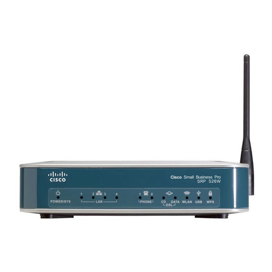
Page 9: Srp 521W Front Panel
PHONE Data WLAN Description Power/Sys Solid green indicates that the SRP is powered on. Green flash indicates that the SRP is booting. LAN Ports 1 to 4 Solid green indicates link. Green flash indicates link traffic. Solid green indicates link. Green flash indicates link (SRP 521W only) traffic. -
Page 10: Srp 521W Back Panel
(PSTN) which is the analog telephone service network that traditional telephone service uses. WAN Port Use this port to connect the Services Ready Platform to your WAN Internet connection. LAN Ports 1 to 4 Use these ports to connect to wired computers and other network devices. -
Page 11: Srp 526W / Srp 527W Back Panel
Ports Ports Feature Description DSL Port Use this port to connect the Services Ready Platform to your DSL connection. Phone Ports 1 to 2 Use these ports to connect to standard analog telephones. FXO Line Port Use this port to connect to analog telephone Service (PSTN) which is the analog telephone service network that traditional telephone service uses. -
Page 12: Side Panels
Press this button for 10 seconds to reset the Services Ready Platform. USB Port Use this port to connect a compatible 3G USB device. For a list of compatible 3G USB modems please check the support community at www.cisco.com/go/srp500. Antenna Services Ready Platform Wi-Fi antenna. -
Page 13: Top View
Feature Description WPS Button To automatically configure wireless security for devices that support WiFi Protected Setup (WPS), press and hold this button until the WPS LED flashes. The device being configured by WPS should be NOTE located next to the Services Ready Platform during setup. -
Page 14: Default Settings
Admin Username admin Admin Password admin DHCP Range 192. 1 68. 1 5. 1 00 to 149 Data VLAN VLAN 1 Voice VLAN VLAN 100, published to the Cisco VOIP phones via CDP Services Ready Platform SRP 500 Series Administration Guide... -
Page 15: Chapter 2: Getting Started With The Configuration Utility
By default, your PC will become a DHCP client of the Cisco SRP 500 Series Services Ready Platform and will receive an IP address in the 192. 1 68. 1 5.x range. Start a web browser. In the Address bar, enter the default IP address of the Cisco STEP 2 SRP 500 Series Services Ready Platform: http://192. -
Page 16: Using The Configuration Utility
If you log in as cisco (with password of cisco), the Setup Wizard will automatically NOTE begin. if you log in as admin, you can start the Setup Wizard by clicking the Administration > Setup Wizard command. Click Log In. The Services Ready Platform Configuration Utility opens. -
Page 17: Configuration Utility Icons
After making your changes, click the Submit button to save your changes. Add Item The Add Item icon lets you add an item to a list. After Icon you have created a new item, click the Submit button to save the new item. - Page 18 Getting Started with the Configuration Utility Using the Configuration Utility Services Ready Platform SRP 500 Series Administration Guide...
-
Page 19: Chapter 3: The Quick Setup Menu
Remote Provisioning. WAN Setup (Ethernet) The WAN Setup page lets you quickly setup your Ethernet WAN interface. Click Quick Setup on the tab and then click WAN Setup in the navigation pane. The STEP 1 WAN Setup page appears. - Page 20 By default, the Router's Internet Connection Type is set to Automatic Configuration - DHCP, which should be kept only if your ISP supports DHCP or you are connecting through a dynamic IP address. Services Ready Platform SRP 500 Series Administration Guide...
- Page 21 URLs. Your ISP will provide you with at least one DNS Server IP Address. If you wish to use another, type that IP Address in one of these fields. You can type up to three DNS Server IP Addresses here. The Router will use these for quicker access to functioning DNS servers.
- Page 22 PPPoE (For ADSL user) Some DSL-based ISPs use PPPoE (Point-to-Point Protocol over Ethernet) to establish Internet Connections. If you are connected to the Internet through a DSL line, check with your ISP to see if they use PPPoE. • User Name and Password Enter the User Name and Password you use when logging onto your ISP through a PPPoE connection.
- Page 23 Your ISP will provide you with the Gateway IP Address. • DNS 1-3 Your ISP will provide you with at least one DNS Server IP Address. If you wish to use another, type that IP Address in one of these fields. You can type up to three DNS Server IP Addresses here.
- Page 24 Your ISP will provide you with the Gateway IP Address. • DNS 1-3 Your ISP will provide you with at least one DNS Server IP Address. If you wish to use another, type that IP Address in one of these fields. You can type up to three DNS Server IP Addresses here.
-
Page 25: Wan Setup (Adsl)
IP address. WAN Setup (ADSL) The WAN Setup page lets you quickly setup your ADSL WAN interface. Click Quick Setup on the tab and then click WAN Setup in the navigation pane. The STEP 1 WAN Setup page appears. - Page 26 Point-to-Point Protocol (PPP): PPP over Ethernet (PPPoE) and PPP over ATM (PPPoA). Multiplexing Select the method used to route different kinds of data through different virtual circuits (VCs) in the ATM network: Logical Link Control (LLC) encapsulation (also called LLC-SNAP) or Virtual Channel (VC) multiplexing (also called VC-Mux).
-
Page 27: Lan Setup
CDVT in cells per second must be entered here. VPI/VCI Auto Detect You can enable or disable automatic detection of the VPI and VCI values (see next) that identify your line to the ATM network. Virtual Circuit The Virtual Path Identifier (VPI) and Virtual Channel Identifier (VCI) are values used to identify your line to your ISP's ATM network. - Page 28 The Quick Setup Menu Basic Configuration Setup Click Quick Setup on the tab and then click LAN Setup in the navigation pane. The STEP 1 LAN Setup page appears. Enter your Internet connection type and any optional LAN settings as necessary.
- Page 29 192. 1 68. 1 5. 1 , the starting IP address must be 192. 1 68. 1 5.2 or greater, but smaller than 192. 1 68. 1 5. 1 49. The default starting IP address is 192. 1 68. 1 5. 1 00.
-
Page 30: Wireless Setup
Otherwise, leave this field blank. Wireless Setup The Wireless Setup page lets you quickly setup the Wireless network. Click Quick Setup on the tab and then click Wireless Setup in the navigation pane. STEP 1 The Wireless Setup page appears. - Page 31 Basic Configuration Setup In the Radio Band field, select a bandwidth for the wireless network. STEP 3 If necessary, select a channel that pertains to the type of bandwidth that you STEP 4 selected in the previous step. If necessary, add or edit the wireless network name (SSID).
- Page 32 When wireless clients survey the local area for wireless Name networks to associate, they detect the SSID broadcast by the gateway. If you want to broadcast the SSID, keep the check box selected. If you do not want to broadcast the SSID, deselect the check box.
- Page 33 Passphrase—To automatically generate keys, enter a passphrase and click the Generate button. Key 1-4—If you want to manually enter the WEP keys, then enter them in the Key 1-4 fields. TX Key—To indicate which WEP key to use, select a transmit key number.
- Page 34 Edit (continued) • WPA2 Personal WPA Algorithms—Select the algorithm(s) you want to use, AES or TKIP + AES. (AES is a stronger encryption method than TKIP.) WPA Shared Key—Enter the key shared by the Router and your other network devices. It must have 8-63 ASCII characters or 64 hex characters.
- Page 35 RADIUS server is reachable from the Router.) WPA Algorithms—Select the algorithm(s) you want to use, TKIP or AES. (AES is a stronger encryption method than TKIP.) RADIUS Server Address (Primary and Secondary)—Enter the IP address of your RADIUS server.
-
Page 36: Remote Provisioning
This feature lets you configure communication with an Access Control Server (ACS) via TR-069 CPE WAN Management Protocol (CWMP). Click Quick Setup on the tab and then click Remote Provisioning in the navigation STEP 1 pane. The Remote Provisioning page appears. - Page 37 The URL for ACS. The format should be http(s):// xxx.xxx.xxx.xxx:port or xxx.xxx.xxx.xxx:port. The xxx.xxx.xxx.xxx is domain name or IP of ACS server; and after “:” is port. Both IP and port must be filled. Services Ready Platform SRP 500 Series Administration Guide...
-
Page 38: Advanced Configuration
The features in Advanced Configuration Setup lets you configure advanced settings with Voice, Mobile Network Setup, the Firewall, and NAT. Voice The Voice option lets you administer and view voice settings. For more details, refer to Voice Settings, on page 108. -
Page 39: Firewall
The Firewall option lets you administer the firewall filter settings. For more details, refer to Firewall, on page The NAT option lets you administer the NAT settings. For more details, refer to NAT, on page Services Ready Platform SRP 500 Series Administration Guide... -
Page 40: Chapter 4: Setting Up The Interfaces Of The Services Ready Platform
Click Interface Setup on the tab and then click WAN in the navigation pane. The STEP 1 Internet Setup page appears. To add or edit interfaces in the WAN Interface List, click the add or edit icons. STEP 2 Services Ready Platform SRP 500 Series Administration Guide... - Page 41 To clone a MAC address to the Services Ready Platform, click Enabled and then STEP 4 enter a MAC address. To clone the MAC address of your computer, click the Clone Your PC’s MAC button. Click Submit to save your settings.
- Page 42 The Details of WAN area shows information about your Detail WAN. When a new interface is chosen or edited using the Add or Edit icons, one of the following options may be available. Services Ready Platform SRP 500 Series Administration Guide...
-
Page 43: Vc Setting
Point-to-Point Protocol (PPP): PPP over Ethernet (PPPoE) and PPP over ATM (PPPoA). Multiplexing Select the method used to route different kinds of data through different virtual circuits (VCs) in the ATM network: Logical Link Control (LLC) encapsulation (also called LLC-SNAP) or Virtual Channel (VC) multiplexing (also called VC-Mux). -
Page 44: Ipoa Settings / Static Ip Setting
Setting up the WAN Interface IPOA Settings / Static IP Setting Select the IPOA Settings / Static IP Setting option if your ISP provides you with a static IP address. Enter the required information as provided by your ISP: Internet IP Address, Subnet Mask, and Default Gateway IP address. - Page 45 Demand connect to your ISP when a connection is needed, and to disconnect when the line to your ISP has been idle for a given amount of time. Connection and disconnection are automatic. You can also adjust the maximum idle time;...
-
Page 46: Pppoa Settings
The default redial period is 20 seconds. Mobile Network You can configure your Services Ready Platform to connect to a 3G USB modem that is connected to its USB interface. Refer to www.cisco.com/go/srp500 more details on compatible 3G USB modem devices. - Page 47 Setting up the Interfaces of the Services Ready Platform Setting up the WAN Interface You must click the Manual option in the Configure Mode field to manually setup your NOTE mobile network card. Click Submit to save your settings. STEP 4...
- Page 48 Connect on Demand enables the modem to automatically re-establish a terminated connection when a user attempts to access the Internet again. In the Max Idle Time field, enter the number of minutes of inactivity that can elapse before your Internet connection terminates.
- Page 49 WAN. Card Status The status of the card. If your Connect Mode is Manual, there will be a button that you can click to connect or disconnect your Modem. Configure Mode Select Auto to allow the Services Ready Platform to automatically detect which card model was inserted and which carrier is available.
-
Page 50: Failover And Recovery (Srp 521W)
3G USB modem devices. While both Ethernet and 3G USB modem may be connected, only one of them can be used to establish a link at a time. Whenever the Internet connection fails, the Services Ready Platform automatically attempts to bring up another connection Failover on another interface. - Page 51 Choose a site on which to perform failover validation in the Failover Validation Site STEP 4 area, either use the Services Ready Platform or enter the IP address for a custom site. If necessary, change the priority of the WAN interfaces by clicking the Up or Down STEP 5 buttons.
- Page 52 Setting up the Interfaces of the Services Ready Platform Setting up the WAN Interface Field Description Ethernet This feature ensures that your Ethernet Internet Connection connection is always connected when available. Recovery Services Ready Platform SRP 500 Series Administration Guide...
-
Page 53: Failover And Recovery (Srp 526W, Srp 527W)
3G USB modem devices. While both DSL and 3G USB modem may be connected, only one of them can be used to establish a link at a time. Whenever the Internet connection fails, the Services Ready Platform automatically attempts to bring up another connection Failover on another interface. - Page 54 Choose a site on which to perform failover validation in the Failover Validation Site STEP 4 area, either use the Services Ready Platform or enter the IP address for a custom site. If necessary, change the priority of the WAN interfaces by clicking the Up or Down STEP 5 buttons.
- Page 55 Internet link. If the link is idle, the Services Ready Platform attempts to ping a destination. If the ping does not reply, the Services Ready Platform assumes the link is down and attempts to fail over to another interface.
-
Page 56: Setting Up The Lan Interface
DHCP Server page appears. You can edit or delete a DHCP entry by clicking the edit or delete icon. STEP 2 Click Add Entry to open the DHCP Add page. From this page you can add a DHCP STEP 3 entry. - Page 57 Setting up the Interfaces of the Services Ready Platform Setting up the LAN Interface Click one of the items in the DHCP List. DHCP information displays in the DHCP Details table. When you click Add Entry, the DHCP Server page opens.
- Page 58 If you already have a DHCP server, then select Disable (no other DHCP features will be available). Show DHCP Allows you to assign a fixed local IP address to a MAC Reservation button address. Services Ready Platform SRP 500 Series Administration Guide...
- Page 59 192. 1 68. 1 5. 1 , the starting IP address must be 192. 1 68. 1 5.2 or greater, but smaller than 192. 1 68. 1 5. 1 49. The default starting IP address is 192. 1 68. 1 5. 1 00.
-
Page 60: Vlan Setting
VLAN Setting. The VLAN Setting page appears. You can edit or delete a VLAN entry by clicking the edit or delete icon. STEP 2 Click Add Entry to open the VLAN Add page. From this page you can add a VLAN STEP 3 entry. - Page 61 If you want to use Spanning Tree Protocol (STP), click this box. Voice VLAN Click this box if you want to use voice. Only use this option in VLAN mode. Address Type Address type. Choices are None, Static IP Address, Dynamic IP Address, and DHCP Server Pool.
-
Page 62: Port Setting
STEP 1 Port Setting. The Port Setting page appears. You can edit a port entry by clicking the edit icon. After you click the edit icon, the STEP 2 Port Edit page opens. Make any necessary changes and click Submit to save your settings. -
Page 63: Setting Up The Wireless Lan
To use Wi-Fi Protected Setup, refer to your wireless adapter's documentation. Click Interface Setup on the tab, and click WiFi Setting, and in the navigation pane. STEP 1 Click Basic Wireless Settings. The Basic Wireless Settings page appears. - Page 64 • If you have only Wireless-B devices, select Wireless-B Only. • If you do not have any wireless devices in your network, select Disabled. From the Radio Band menu, you can select the wireless bandwidth on your STEP 3 network. There are three options you can select: Auto, Standard - 20MHz Channel, and Wide - 40MHz Channel.
- Page 65 Setting up the Wireless LAN Field Description Wide Channel If you selected Wide - 40MHz Channel for the Radio Band setting, this setting will be available for your primary Wireless-N channel. Select any channel from the drop-down menu. Standard Channel...
-
Page 66: Wireless Protected Setup
From Select a SSID menu, choose the SSID beacon interval and RTS threshold STEP 2 settings you want to configure. In the WPS field, select Disabled if you do not want to use the WiFi Protected STEP 3 Setup. There are three methods available to configure your WiFi settings using WPS. Use NOTE the method below that applies to the client device you are configuring. -
Page 67: Wps Method 3
Use this method if your client device asks for the PIN number of the Services Ready Platform. Enter the PIN number listed on this page. (It is also listed on the label on the bottom STEP 1 of the Services Ready Platform.) After the client device has been configured, click OK. - Page 68 Setting up the Interfaces of the Services Ready Platform Setting up the Wireless LAN Field Description Select a SSID Choose the SSID for the wireless network that you want to configure. The default is SSID1. Wi-Fi Protected WiFi Protected Setup (WPS) option. The default is Setup Enabled.
-
Page 69: Wireless Mac Filter
The list can be sorted by Client Name, Interface, IP Address, MAC Address, and Status. Select Save to MAC Address Filter List for any device you want to add to the list. STEP 6 Then click Add. - Page 70 Setting up the Wireless LAN Field Description Select a SSID The MAC filter settings to apply to the SSID. The default is SSID1. Enabled/Disabled The option to filter wireless users by MAC Address. Services Ready Platform SRP 500 Series Administration Guide...
-
Page 71: Advanced Wireless Settings
To change these settings, wireless must first be enabled. NOTE Click Interface Setup on the tab and then click WiFi Setting in the navigation pane. STEP 1 Click Advanced Wireless Settings. The Advanced Wireless page appears. - Page 72 Setting up the Interfaces of the Services Ready Platform Setting up the Wireless LAN If a network packet is smaller than the preset RTS threshold size, the RTS/CTS mechanism will not be enabled. The Services Ready Platform sends Request to Send (RTS) frames to a particular receiving station and negotiates the sending of a data frame.
- Page 73 Services Ready Platform can transmit at all standard wireless rates (1-2 Mbps, 5.5 Mbps, 11 Mbps, 18 Mbps, and 24 Mbps). Other options are 1-2 Mbps, for use with older wireless technology, and All, when the Services Ready Platform can transmit at all wireless rates. The Basic Rate is not the actual rate of data transmission.
- Page 74 The rate of data transmission should be set depending on the speed of your Wireless-N networking. You can select from a range of transmission speeds, or you can select Auto to have the Services Ready Platform automatically use the fastest possible data rate and enable the Auto-Fallback feature.
-
Page 75: Wmm Setting
The Services Ready Platform features WMM Support. The No Acknowledgement feature is available only when the WMM Support feature is enabled. Click Interface Setup on the tab and then click WiFi Setting in the navigation pane. STEP 1 Click WMM Setting. The WMM Setting page appears. -
Page 76: Using The Management Interface
Click Interface Setup on the tab and then click Management Interface in the STEP 1 navigation pane. The Management Interface page appears. Click on the loopback icon to change the IP address and subnet mask for each STEP 2 loopback interface. The Management Interface page opens. - Page 77 Setting up the Interfaces of the Services Ready Platform Using the Management Interface Field Description IP Address The IP address for the loopback interfaces. The IP Address used for the loopback interface assumes a subnet mask of NOTE 255.255.255.255. Services Ready Platform SRP 500 Series Administration Guide...
-
Page 78: Chapter 5: Configuring The Network
Static Routing sets up a fixed route to another network destination. Static Routes The settings for Static Routes are set on this page. It shows the current static routing list and details of the selected route. Click Network Setup on the tab and then click Routing in the navigation pane. The STEP 1 Static Route Rule page appears. - Page 79 Enter a static route name, destination IP address/subnet mask, and Services STEP 3 Ready Platform IP address. Click Submit to save your settings. STEP 4 After clicking the Add Entry button, the Static Routing Add page opens. Services Ready Platform SRP 500 Series Administration Guide...
-
Page 80: Rip
STEP 3 Set RIP timer values. STEP 4 In the RIP List, select the Interface that you want to enable the RIP function. Or you STEP 5 can add the network address to join the RIP. Click Submit to save your settings. -
Page 81: Intervlan Routing
Intervlan Routing This page allows you to enable or disable intervlan routing. When enabled, this feature enables hosts that belong to different VLANs to route to each other. If disabled, communications between hosts that belong to different VLAN are blocked. Select either Enabled or Disabled and then Submit to enable or disable Intervlan routing. -
Page 82: Port Forwarding
WAN for a specific application port, or port range, to an internal device on the local area network. For example, if you have a web server on the Services Ready Platform LAN, you can setup a port forward for all requests to port 80 to be sent to the internal web server IP address. - Page 83 Type of port forwarding: choices are Single Port Type Forwarding or Port Range Forwarding. Application Name A list of applications. Select an application from the list. Enter a Name The name of the application. Wan Interface Name The WAN Interface.
-
Page 84: Port Range Triggering
This is disabled (unchecked) by default. Port Range Triggering The settings for Port Range Triggering are set on this page. It instructs the Router to watch outgoing data for specific port numbers. The IP address of the computer that sends the matching data is remembered by the Router, so that when the requested data returns through the Router, the data is sent to the proper computer by way of IP address and port mapping rules. - Page 85 The name of the application. The WAN interface. The LAN interface. Triggered Range The starting and ending port numbers of the triggered port range. Check with the Internet application documentation for the port number(s) needed. Forwarded Range Enter the starting and ending port numbers of the forwarded port range.
-
Page 86: Qos
Bandwidth control allows the Services Ready Platform to control the maximum bandwidth for upstream data transmissions. Click Network Setup on the tab and then click QoS in the navigation pane. Click STEP 1 Bandwidth Control. The Bandwidth Control page appears. -
Page 87: Qos Policy
87, for more details on setting up QoS priorities. QoS Policy The settings for QoS Rule are set on this page. After clicking Add Entry button, it can create another QoS Rule. The QoS Policy shows the current QoS list and details of the selected QoS rule. -
Page 88: Qos Settings
Configuring the Network QoS Settings Quality of Service (QoS) ensures better service to high-priority types of network traffic. Field Description Category There are four categories available. Select one of the following: Applications, MAC Address, Ethernet Port, or VLAN. Applications Application type for the QoS priority. -
Page 89: Cos To Queue
CoS To Queue The CoS To Queue feature lets you set priorities to specified VLANs. Click Network Setup on the tab and then click QOS in the navigation pane. Click STEP 1 CoS To Queue. The CoS To Queue page appears. -
Page 90: Dscp To Queue
The DSCP to Queue Page enables mapping DSCP (IP DiffServ) values to specific queues. Click Network Setup on the tab and then click QOS in the navigation pane. Click STEP 1 DSCP To Queue. The DSCP To Queue page appears. -
Page 91: Firewall
Defines the traffic forwarding queue to which the DSCP priority is mapped. Firewall Firewall Filter A firewall enhances network security and uses Stateful Packet Inspection (SPI) for more detailed review of data packets entering your network. Services Ready Platform SRP 500 Series Administration Guide... - Page 92 Configuring the Network Firewall Click Network Setup on the tab and then click Firewall in the navigation pane. Click STEP 1 Firewall Filter. The Firewall page appears. Select Enabled to enable firewall protection. STEP 2 Click the Filter Anonymous Internet Requests option to keep your network from STEP 3 being “pinged,”...
- Page 93 Java Java is a programming language for websites. If you deny Java, you run the risk of not having access to Internet sites created using this programming language. To enable Java filtering, click the box.
-
Page 94: Internet Access Control
Internet Access Control The settings for Internet Access Control are set on this page. Click Network Setup on the tab and then click Firewall in the navigation pane. Click STEP 1 Internet Access Control. The Internet Access Control page appears. - Page 95 Enable or disable this feature. The default is Disabled. Days/Times You can specify the days and times when you want this policy to be enforced. Select the individual days when the policy will be in effect, or select Everyday. Then enter a range of hours and minutes when the policy will be in effect, or select 24 Hours.
-
Page 96: Pppoe Relay
(LNS) or tunnel switch (multihop node). The relay functionality of this feature allows the LNS or tunnel switch to advertise the services it offers to the client, thereby providing end-to-end control of services between the LNS and a PPPoE client. - Page 97 Configuring the Network PPPoE Relay Click Network Setup on the tab and then click PPPoE Relay in the navigation pane. STEP 1 The PPPoE Relay page appears. Click Add Entry. The PPPoE Relay page opens. STEP 2 Choose a WAN option.
-
Page 98: Ddns
The Services Ready Platform offers a Dynamic Domain Name System (DDNS) feature. DDNS lets you assign a fixed host and domain name to a dynamic Internet IP address. It is useful when you are hosting your own website, FTP server, or other server behind the Services Ready Platform. - Page 99 Description User Name The user name from DynDNS.org. Password The password from DynDNS.org. Host Name Your host name. This should be in the format of name.dyndns.org. System The DynDNS service you use: Dynamic, Static, or Custom. Mail Exchange The address of your mail exchange server, so the e-mail (Optional) to your DynDNS address go to your mail server.
- Page 100 DDNS Field Description Mail Exchange This feature allows the mail exchange server to be a (Backup MX) backup. To enable this feature, use the default setting, Enabled. To disable this feature, select Disable. if you are not sure, which seting to select, use the default setting, Enabled.
- Page 101 Description E-mail Address The E-mail Addres from TZO account. TZO Key The key from TZO account. Domain Name Your host name. This should be in the format of name.tzo.org. Internet IP Address Your current IP address. Status Your DDNS status.
-
Page 102: Dmz
Configuring the Network DMZ allows one local user to be exposed to the Internet for use of a special- purpose service such as Internet gaming and videoconferencing. DMZ hosting forwards all the ports at the same time to one PC. The Port Range Forwarding is more secure because it only opens the ports you want to have opened, while DMZ hosting opens all the ports of one computer, exposing the computer to the Internet. -
Page 103: Igmp
Click Network Setup on the tab and then click IGMP in the navigation pane. The STEP 1 IGMP page appears. Select the version you want to support, IGMP v1, IGMP v2, or IGMP v3. If you are STEP 2 not sure which version to select, use the default setting, IGMP v2. - Page 104 Configuring the Network IGMP If you want to allow multicast traffic through the Services Ready Platform for your STEP 3 multimedia application devices, use the default setting, Enabled. Otherwise, select Disabled. If you use IPTV applications and want to allow immediate channel swapping or STEP 4 flipping without lag or delays, select Enabled .
-
Page 105: Upnp
If you want to use UPnP, use the default setting, Enabled. Otherwise, select STEP 2 Disabled. If you do not want to be able to make manual changes to the Services Ready STEP 3 Platform while using the UPnP feature, select Disabled. Otherwise, use the default setting, Enabled. -
Page 106: Cdp Setting
Click Network Setup on the tab and then click CDP Setting in the navigation pane. STEP 1 The CDP Setting page appears. - Page 107 Configuring the Network CDP Setting Field Description CDP options. Enable All, Disabled All and Per Port. The default is Per Port. CDP Timer The CDP timer. The CDP timer range is 5-900. CDP Hold Timer The CDP Hold timer. The CDP timer range is 10-255.
-
Page 108: Chapter 6: Voice Settings
Voice Settings This chapter describes how to administer and view voice settings. • Info, page 108 • System, page 109 Info The Info page provides information about the product, system, and line status. Services Ready Platform SRP 500 Series Administration Guide... -
Page 109: System
Voice Settings System System The System page lets you set a password for system configuration for voice. Field Description Restricted Access Enter the domain names permitted to access the Domains System. Miscellaneous Settings Syslog Server Enter the IP address of the syslog server, which logs system information and critical events of the System. -
Page 110: Sip
Voice Settings The SIP page lets you configure numerous SIP parameters and values. Services Ready Platform SRP 500 Series Administration Guide... -
Page 111: Provisioning
Voice Settings Provisioning Provisioning The Provisioning page lets you configure various profiles and parameters. Services Ready Platform SRP 500 Series Administration Guide... - Page 112 This parameter is in units of 20 seconds; the default value of 2 represents 40 seconds. This feature is disabled when this parameter is set to zero. This feature can be used to prevent an overload of the provisioning server when a large number of devices power-on simultaneously.
- Page 113 The device does not resync while one of its phone lines is active. Because a resync can take several seconds, it is desirable to wait until the device has been idle for an extended period before resyncing. This allows a user to make calls in succession without interruption.
- Page 114 Profile Rule resync operation has completed. If a resync is triggered Profile Rule D: and Profile Rule is blank, Profile Rule B, C, and D are still evaluated and executed. The default is (empty). Log Resync...
- Page 115 URL. A configuration report is generated in response to an authenticated SIP NOTIFY message, with Event: report. The report is an XML file containing the name and value of all the device parameters. This parameter may optionally contain an encryption key.
- Page 116 Voice Settings Provisioning Field Description Log Upgrade Syslog message issued at the start of a firmware Request Msg upgrade attempt. The default is $PN $MAC -- Requesting upgrade $SCHEME://$SERVIP:$PORT$PATH. Log Upgrade Syslog message issued after a firmware upgrade Success Msg attempt completes successfully.
-
Page 117: Regional
Voice Settings Regional Regional The Regional page lets you configure various tones and patterns. Services Ready Platform SRP 500 Series Administration Guide... -
Page 118: Chapter 7: Configuring Vpn
VPN policies. Clicking the Add Entry button opens the IKE Policy Configuration page. Click VPN on the tab and then click Site to Site IPSec VPN in the navigation pane. STEP 1 Click IKE Policy. The IKE Policies page appears. - Page 119 Unique name used for the VPN policy. Exchange Mode Main or Aggressive mode selection. IKE SA Parameters Encryption Encryption algorithms in IKE SA. Choices are DES, 3DES, Algorithm AES128, AES192, or AES256. Authentication Authentication algorithm in IKA SA. Choices are MD5 Algorithm and SHA1.
-
Page 120: Ipsec Policy
KEY type. Clicking the Add Entry button opens the VPN Policy Configuration page. Click VPN on the tab and then click Site to Site IPSec VPN in the navigation pane. STEP 1 Click IPSec Policy. The IPSec Policy page appears. - Page 121 Configuring VPN IPSec Policy Choose an integrity algorithm. STEP 8 Enter auto policy parameters. STEP 9 Enter local and remote traffic selection settings. STEP 10 Click Submit to save your settings. STEP 11 Services Ready Platform SRP 500 Series Administration Guide...
- Page 122 There are two types, Auto Policy and Manual Policy. The Auto Policy type will use IKE protocol to negotiate random keys, therefore it first requires an IKE policy as well. The Manual Policy type will NOT use IKE, which is more simple, but less secure. Remote Endpoint The remote gateway that you are going to connect to establish a IPSec VPN tunnel.
-
Page 123: Gre Tunnel
IP tunnels, creating a virtual point-to-point link to Cisco routers at remote points over an IP internetwork. Clicking the Add Entry button opens the GRE Configuration page. Click VPN on the tab and then click GRE Tunnel in the navigation pane. The GRE STEP 1 page appears. - Page 124 GRE Tunnel Click Submit to save your settings. STEP 8 Field Description Number The tunnel number that you are going to configure. Status The status of the tunnel. Tunnel Name The name of the tunnel. Enable This field indicates whether you want to enable or disable the tunnel.
-
Page 125: Vpn Passthrough
Modify Remote IP You can modify the Remote IP Address and Subnet Address/Subnet Mask in this field. Use the Add button to add it into the Mask list of Remote IP Address/Subnet Mask. For example: 192. 1 68.2.0/24 or 192. 1 68.3.0/32. - Page 126 Configuring VPN VPN Passthrough Click VPN on the tab and then click Site to Site IPSec VPN in the navigation pane. STEP 1 Click VPN Passthrough. The VPN Passthrough page appears. To enable IPSec passthrough, click Enabled. STEP 2 To enable PPTP passthrough, click Enabled.
- Page 127 VPN Passthrough Field Description L2TP Passthrough Layer 2 Tunneling Protocol is the method used to enable Point-to-Point sessions via the Internet on the Layer 2 level. L2TP Pass-Through is enabled by default. To disable L2TP Passthrough, select Disabled. Services Ready Platform SRP 500 Series Administration Guide...
-
Page 128: Chapter 8: Administration Settings
Backup & Restore, page 142 • Reboot, page 144 Web Access Management You can configure access settings and remote acess rules from the Web access management features. Settings This page allows you to change the access settings of the Services Ready Platform. - Page 129 Administration Settings Web Access Management Click Administration on the tab and then click Web Access Management in the STEP 1 navigation pane. The Web Access Management page appears. Select Web Access options. STEP 2 Select Remote Access options. STEP 3 Click Submit to save your settings.
-
Page 130: Remote Management
If enabled, the Services Ready Platform firmware can be upgraded from Internet. Allowed Remote IP If you want to be able to access the Router from any Address external IP address, select Any IP Address. If you want to specify an external IP address or range of IP addresses, then select the second option and complete the fields provided. - Page 131 Enter the URL for ACS. The format should be http(s)://xxx.xxx.xxx.xxx:port or STEP 3 xxx.xxx.xxx.xxx:port. The xxx.xxx.xxx.xxx is domain name or IP of ACS server; and after “:” is port. Both IP and port must be filled. Enter the ACS username and password. STEP 4 Enter the Connection request username and password.
-
Page 132: Snmp
The URL for ACS. The format should be http(s):// xxx.xxx.xxx.xxx:port or xxx.xxx.xxx.xxx:port. The xxx.xxx.xxx.xxx is domain name or IP of ACS server; and after “:” is port. Both IP and port must be filled. ACS Username The username for ACS. The default username is OUI- Serial Number;... -
Page 133: Local Tftp
Local TFTP This feature lets you download files to the Services Ready Platform remotely and then use it as a local TFTP server to serve files to hosts on the LAN such as IP phones. Services Ready Platform SRP 500 Series Administration Guide... - Page 134 Administration Settings Remote Management Click Administration on the tab and then click Remote Management in the STEP 1 navigation pane. Click Local TFTP. The Local TFTP Control page appears. Click Enabled to enable TFTP. STEP 2 Click Submit to save your settings.
-
Page 135: Time Setup
STEP 3 Ready Platform to automatically adjust for daylight saving time. If you want to use the default Network Time Protocol (NTP) server, use the default STEP 4 setting, Auto. If you want to specify the NTP server, select Manual, and enter the URL or IP address of the NTP server you want to use. - Page 136 (NTP) server, use the default setting, Auto. If you want to specify the NTP server, select Manual, and enter the URL or IP address of the NTP server you want to use. Services Ready Platform SRP 500 Series Administration Guide...
-
Page 137: Setup Wizard
Setup Wizard to continue. User List The settings for User List page let you change the password for the Admin login and the User login. Click Administration on the tab and then click User List in the navigation pane. The STEP 1 User List page appears. -
Page 138: User Privilege Control
User Privilege Control The User Privilege Control screen lets the administrator to adjust the privileges assigned to the user. Click Administration on the tab and then click User Privilege Control in the STEP 1 navigation pane. The User Privilege Control page opens. - Page 139 Outgoing Log will display a temporary log of the local IP addresses, destination URLs/IP addresses, and service/port numbers for the outgoing Internet traffic. Click Administration on the tab and then click Log in the navigation pane. The Log STEP 1 page appears.
-
Page 140: Factory Defaults
Log, Outgoing Log, or DHCP Client Log. Factory Defaults You can set the Services Ready Platform to its settings as it was when it was shipped from the factory. Click Administration on the tab and then click Factory Defaults in the navigation STEP 1 pane. - Page 141 Administration Settings Factory Defaults Click Yes in the Restore Voice Factory Defaults to restore the voice settings to STEP 3 factory defaults. Click Submit to save your settings. STEP 4 Field Description Restore Router To reset the Services Ready Platform settings to the Factory Defaults default values, select Yes.
-
Page 142: Firmware Upgrade
Backup Configuration The Backup Configuration feature lets you to backup the configuration settings of the Services Ready Platform to a file which you can use later to restore the Services Ready Platform to the same settings. Services Ready Platform SRP 500 Series Administration Guide... -
Page 143: Restore Configuration
Administration Settings Backup & Restore Click Administration on the tab and then click Backup & Restore in the navigation STEP 1 pane. Click Backup Configuration. The Backup Configuration page appears. Click Backup to save the configuration of the Services Ready Platform. -
Page 144: Reboot
Ready Platform, click Browse and locate a backup file and click Restore. You must have previously backed up the NOTE configuration settings of the Services Ready Platform. Reboot You can reboot the Services Ready Platform from the configuration utility. Services Ready Platform SRP 500 Series Administration Guide... -
Page 145: Status
Administration Settings Status Click Administration on the tab and then click Reboot in the navigation pane. The STEP 1 Reboot page appears. Click Reboot to reboot the Services Ready Platform. STEP 2 Field Description Reboot Click Reboot to power cycle the Services Ready... -
Page 146: Switch Setting
Switch Setting Switch Setting On DSL models SRP 526W and SRP 527W, Ethernet port 4 can be configured as a WAN port. You can also set the “jumbo mode” packet size on this screen. When Ethernet port 4 is configured as a WAN port, the DSL port becomes inactive. - Page 147 Enable or disable the DSL port. When disabled, the LAN port 4 can be used an Ethernet WAN port. Jumbo Mode The size of the jumbo packet. Choices are 1522 or 2048 bytes. Services Ready Platform SRP 500 Series Administration Guide...
-
Page 148: Chapter 9: Using Services Ready Platform Diagnostics
Detect Active LAN Clients, page 150 Ping Test You can perform a ping test from the configuration utility. Click Diagnostics on the tab and then click Ping Test in the navigation pane. The STEP 1 Ping Test page appears. Enter an IP or URL address. -
Page 149: Traceroute Test
Traceroute Test You can perform a traceroute test from the configuration utility. Click Diagnostics on the tab and then click Traceroute Test in the navigation pane. STEP 1 The Traceroute Test page appears. Enter an IP or URL address. -
Page 150: Detect Active Lan Clients
STEP 2 Select how many seconds you wish to perform this search: 5, 10, or 15 seconds. STEP 3 Click Start to Search to start the test. Click Close to close the results and return to STEP 4 the previous screen. - Page 151 Using Services Ready Platform Diagnostics Detect Active LAN Clients Field Description LAN Interface Interface to search. Search Time Time to perform the search in seconds. Services Ready Platform SRP 500 Series Administration Guide...
-
Page 152: Chapter 10: Viewing The Services Ready Platform Status
IGMP Status, page 168 • VPN Status, page 169 • CDP Neighbor Information, page 169 Router Settings You can view various status parameters of the Services Ready Platform from the configuration utility. Services Ready Platform SRP 500 Series Administration Guide... - Page 153 Viewing the Services Ready Platform Status Router Settings Click Status on the tab and then click Router in the navigation pane. The Router STEP 1 page appears. Field Description Model The product name of the Services Ready Platform. Hardware Version The current hardware version number of the Services Ready Platform.
-
Page 154: Firewall Status
The Wireless SSID and level. Firewall Status You can view firewall status from the configuration utility. Click Status on the tab and then click Firewall Status in the navigation pane. The STEP 1 Firewall page appears. Services Ready Platform SRP 500 Series Administration Guide... - Page 155 Viewing the Services Ready Platform Status Firewall Status Field Description Internet Access Policy Policy Rule number associated with the Internet Access Control. Policy Name Policy name associated with the Internet Access Control. Status Enable or disable this policy rule. Passed (pkts) Packet passed by this rule.
-
Page 156: Interface Information
Traffic volume dropped by this firewall chain. Interface Information You can view interface information from the configuration utility. Click Status on the tab and then click Interface Information in the navigation pane. STEP 1 The Interface Information page appears. Services Ready Platform SRP 500 Series Administration Guide... - Page 157 Interface List Interface The current VLAN interface including the LAN and WAN side. An Ethernet WAN interface is shown as “WAN” and an ADSL WAN interface is shown as “PVC.” Connect Type The kind of protocol to use/apply on this interface.
-
Page 158: Wireless Network
Click this button to reset to 0 the count of TX and RX packets. Wireless Network The Wireless Network page displays information about your wireless networks. Click Status on the tab and then click Wireless Network in the navigation pane. The STEP 1 Wireless Network page appears. Field... -
Page 159: Wireless Client Information
The current settings of the wireless network. Wireless Client Information You can view wireless client information from the configuration utility. Click Status on the tab and then click Wireless Client Information in the navigation STEP 1 pane. The Wireless Client Information page appears. -
Page 160: Mobile Network
Mobile Network You can view mobile network information from the configuration utility. Click Status on the tab and then click Mobile Network in the navigation pane. The STEP 1 Mobile Network page appears. - Page 161 Model name of this 3G data card. Card Firmware Firmware revision of this 3G data card. SIM Status SIM card status. (SIM ready or pin code needed). IMSI IMSI number of this 3G data card. Service Type 3G service type.
- Page 162 Signal strength Signal strength. Card status The status of the card: Connecting, Connected, Disconnecting, Disconnected or Card is not activated. If the USB 3G data card is CDMA2000 (EVDO) Field Description IP Address IP address associated to this 3G connection.
-
Page 163: Dhcp Server Information
Disconnecting, Disconnected or Card is not activated. DHCP Server Information You can view DHCP Server Information from the configuration utility. Click Status on the tab and then click DHCP Server Information in the navigation STEP 1 pane. The DHCP Server Information page appears. -
Page 164: Qos Status
Platform supports 5 queues, each of them has a different priority, constant rate, and burst rate which are configurable. Click Status on the tab and then click QoS Status in the navigation pane. The QoS STEP 1 Status page appears. -
Page 165: Routing Table
Status of the low priority queue. Routing table You can view Routing Table information from the configuration utility. Click Status on the tab and then click Routing Table in the navigation pane. The STEP 1 Routing Table page appears. Services Ready Platform SRP 500 Series Administration Guide... -
Page 166: Arp Table
The Subnet Mask determines which portion of an IP address is the network portion, and which portion is the host portion. Gateway This is the IP address of the gateway device that allows for contact between the gateway and the network or host. Interface This interface tells you whether the Destination IP Address is on the LAN &... -
Page 167: Rip Status
Viewing the Services Ready Platform Status RIP Status Click Status on the tab and then click ARP Table in the navigation pane. The ARP STEP 1 Table page appears. Field Description IP address IP address of the device. HW type Hardware type of the device. -
Page 168: Igmp Status
Viewing the Services Ready Platform Status IGMP Status Click Status on the tab and then click RIP Status in the navigation pane. The RIP STEP 1 Status page appears. IGMP Status You can view IGMP staus information from the configuration utility. -
Page 169: Vpn Status
Only applies to the “AUTO” mode. CDP Neighbor Information You can view Neighbor information from the configuration utility. Click Status on the tab and then click CDP Neighbor Information in the navigation STEP 1 pane. The CDP Neighbor Information page appears. - Page 170 Device ID The device ID of the neighbor. Local Interface The local Services Ready Platform name. Hold Time The hold time before which CDP will throw away packets. Capability The class of the neighbor. Port ID The port number of the neighbor.
- Page 171 Viewing the Services Ready Platform Status CDP Neighbor Information Services Ready Platform SRP 500 Series Administration Guide...
-
Page 172: Appendix A: Specifications
Humidity Storage 5% to 90% Non-Condensing Humidity Voltage Range 100-240V 50/60Hz AC Dimensions (W x D x H): 170mm (6.69 inches) x 170mm (6.69 inches) x 42mm (1.65 inches) Weight 400g Feature SRP 526W ADSL2+ Annex B 4 Fast Ethernet Ports Wireless 802. - Page 173 Humidity Storage 5% to 90% Non-Condensing Humidity Voltage Range 100-240V 50/60Hz AC Dimensions (W x D x H): 170mm (6.69 inches) x 170mm (6.69 inches) x 42mm (1.65 inches) Weight 440g Feature SRP 527W ADSL2+ Annex A 4 Fast Ethernet Ports Wireless 802.
-
Page 174: Appendix B: Where To Go From Here
Where to Go From Here Cisco provides a wide range of resources to help you and your customer obtain the full benefits of the Services Ready Platform. Product Resources Support Cisco Small Business www.cisco.com/go/smallbizsupport Support Community Online Technical Support www.cisco.com/support...