Table of Contents
Advertisement
Advertisement
Table of Contents

Related Manuals for Alcatel OS6850-48L


Summary of Contents for Alcatel OS6850-48L
-
Page 1: Omniswitch 6800 Series
® OmniSwitch 6800 Series Getting Started Guide 060195-10, Rev. B October 2006... - Page 2 The features and specifications described in this guide are subject to change without notice. Copyright © 2006 by Alcatel Internetworking, Inc. All rights reserved. This document may not be reproduced in whole or in part without the express written permission of Alcatel Internetworking, Inc.
-
Page 3: Table Of Contents
Unpacking the Chassis ....10 Features ........1 Recommendations . - Page 4 ........
- Page 5 Certified Directory ..... . 42 LED States ....... 52 How can I tell which directory the switch 10/100/1000 LEDs .
- Page 6 October 2006...
-
Page 7: Omniswitch 6800 Series
Ethernet switches. These switches provide wire LINK sole LINK rate Layer 2 forwarding and Layer 3 routing with advanced services. All offer four combo ports consisting of four shared Spee OmniSwitch 6800-48 10/100/1000 ports and four 1000 Mbps fiber SFP ports. -
Page 8: Network Applications
Stacking switches provides scalability by allowing users to quickly and easily expand 10/100/1000 port density. Twenty- Whether operating as a single switch or as a stack, the four 10/100/1000 ports are added for each OS6800-24 brought OmniSwitch 6800 Series offers effective availability, resil-... -
Page 9: Availability Features
The switch provides a broad variety of availability features. OmniSwitch 6800-24 (OS6800-24) Availability features are hardware- and software-based safe- guards that help prevent the loss of data flow in the unlikely event of a subsystem failure. In addition, some availability The OmniSwitch 6800-24 is a stackable edge/workgroup... -
Page 10: Omniswitch 6800-48 (Os6800-48)
The OmniSwitch 6800-48 is a stackable edge/workgroup The OmniSwitch 6800-U24 is a standalone edge/workgroup switch offering 48 10/100/1000Base-T ports, as well as four switch offering 24 1000 Mbps SFP ports, as well as four SFP ports for high speed connections. combo 10/100/1000Base-T ports. -
Page 11: Omniswitch 6800-24L (Os6800-24L)
The OmniSwitch 6800-48L is a stackable edge/workgroup switch offering 20 non combo 10/100/1000Base-T ports, 4 switch offering 44 non combo 10/100/1000Base-T ports, 4 combo 10/100/1000Base-T ports, as well as four SFP ports for combo 10/100/1000Base-T ports, as well as four SFP ports for high speed connections. -
Page 12: Os6800-Xni-U2 10 Gigabit Uplink Module
10 Gigabit expansion module (OS6800-XNI-U2). OS6800-BPS-SHLF backup power supply shelf • The slot for the expansion module is located at the rear panel of the switch chassis. The 10 Gigabit Ethernet expansion OS6800-BPS 225W backup power supply module •... - Page 13 Because the OmniSwitch 6800 Series backup power supply system is chassis-based—with each chassis supporting up to eight backup power supplies—this provides 1:1 redundancy for stacks of up to eight switches. October 2006 OmniSwitch 6800 Series...
-
Page 14: Setting Up The Hardware
Be sure to allow adequate room for proper air ventila- A single OS6800-48 weighs approximately 14.41 lbs. • tion and access at the front, back, and sides of the (6.54 Kg). A stack of eight OS6800-48 switches weighs switch. No clearance is necessary at the top or bottom approximately 115 lbs (52.3 Kgs). -
Page 15: Os6800-U24
OmniSwitch CLI Reference Guide OS6800-24L OmniSwitch 6800/6850/9000 Switch Management Guide A single OS6800-24L weighs approximately 13.88 lbs. (6.30 Kg). A stack of eight OS6800-24L switches weighs OmniSwitch 6800/6850/9000 Network Configuration approximately 111 lbs (50.4 Kgs). Guide OmniSwitch 6800/6850/9000 Advanced Routing... -
Page 16: Unpacking And Initial Setup
(ESD) and physical damage, do not unpack these items until they are ready to be installed. Instructions Carefully cut the tape along the seam at the top of the box containing the chassis. Lift the box’s top flaps. Remove any smaller boxes or pouches that are enclosed and set them aside. -
Page 17: Setting Up The Switch
Setting Up the Switch Never obstruct the air vents located at the left and right sides of the chassis. Note. Due to their airflow and access requirements, Note. Clearance is not required at the top and bottom of OmniSwitch 6800 Series switches cannot be wall- the chassis. -
Page 18: Tabletop Mounting Steps
Rack-Mounting the Switch Tabletop Mounting Steps To install the switch as a tabletop unit, follow the steps below: Refer to the important guidelines below before installing the OmniSwitch chassis in a rack. Position the chassis on the table or bench where it is to be installed. -
Page 19: Rack Mounting Steps
After the rack-mount flanges are secured to the chas- • access recommendations before installing. sis, mark the holes on the rack where the switch is to be installed. Rack Mounting Steps Lift and position the switch until the rack-mount To rack-mount the switch, follow the steps below: flanges are flush with the rack post. -
Page 20: Installing Combo Port Sfps
XFP transceivers, refer to the OmniSwitch 6800 Series sure that all screws are securely tightened. Hardware Users Guide. If you are installing multiple switches in a rack to form a stacked configuration, repeat steps 1 through 7 for all Installing Backup Power Supply switches in the stack. -
Page 21: Completing A Stacked Configuration
End View of Stacking Cable Connector Supported Cabling Patterns Starting from the top of the stack, insert one end of the stacking cable into either stacking port A or stacking port Each switch provides two stacking ports: stacking port A and B. - Page 22 Repeat this procedure until all switches in the stack are To provide added resiliency and redundancy, you must connected (see illustrations a, b, and c below). install the redundant stacking cable to connect the top switch in the stack to the bottom switch. Connect the redundant cable now.
- Page 23 Once all stacking cable connectors are inserted, tighten the captive screws at the left- and right-hand sides of each connector, as shown. Be sure not to overtighten the screws. Tightening Stacking Connector Captive Screws Now that all switches in the stack are connected, the next step is to connect all required network and manage- ment cables.
-
Page 24: Connections And Cabling
Connections and Cabling Serial Connection Default Settings Once your switch is properly set up and all required hardware components are installed, you should connect all network and management cables required for your network applications. The default settings for the serial connection are as follows:... -
Page 25: Booting Omniswitch 6800 Series Switches
LED information. The default value is 1. states: If any of the LED state differs from the states shown in the LED States for a Standalone Switch table above, refer to page 58 for more information. -
Page 26: Booting Stacked Configurations
LED states. Once the switches have been connected into a virtual chassis and the network cables have been attached, the next step is to LED States for a Stacked Configuration manually power on the stack. The OmniSwitch 6800 Series Solid green for all switches switch does not use an on/off switch. -
Page 27: Dynamic Slot Numbering And Management Role Assignment
If any of the LED state differs from the states shown in the Note. As the slot numbers are dynamically assigned, table above, refer to page 58 for more information. Contact boot.slot.cfg files are auto-generated in the /flash direc- Alcatel Customer Support if the unexpected LED state tory of each switch. -
Page 28: Manual Slot Numbering And Management Role Assignment
2 to have the next slot number preference. It is assigned an idle role and given the slot number 3. The switch immediately below slot 3 is given the slot number 4, and so on. When the bottom of the stack is reached, the slot numbering sequence resumes at the top of the stack, as shown. -
Page 29: Your First Login Session
Command When you first log in to the switch or stack, you will be Line Interface (CLI) and configure basic information. -
Page 30: Assigning An Ip Address To The Switch Or Stack
IP -> address must be configured. To assign an IP address to a switch, first configure an IP inter- More Information on User Accounts. A user account face (e.g., with the interface name “remote”), and then assign includes a login name, password, and user privileges. -
Page 31: Assigning Ip Addresses To Switches In A Stacked Configuration
Security is a key feature on OmniSwitch 6800 Series switches. It is important that all switches in a stacked configuration have As a result, when you access the switch for the first time, you the same assigned IP address. This way, if a failover should must use a direct console port connection. -
Page 32: Unlocking Specified Session Types
4 concurrent sessions sions allowed New password settings are automatically saved in real time to the local user database; the user is not required to enter an Total sessions (Telnet, FTP, 13 concurrent sessions additional command in order to save the password informa- HTTP, console) tion. -
Page 33: Setting The System Time Zone
For example: -> system date 06/27/2002 If you require a time zone that is specific to your region—or if you need to enable Daylight Savings Time (DST) on the switch—you can configure these settings via the... -
Page 34: Setting Optional System Information
Specifying the Switch’s Location An administrative contact is the person or department in charge of the switch. If a contact is specified, users can easily It is recommended that you use a physical labeling system for find the appropriate network administrator if they have ques- locating and identifying your switch(es). -
Page 35: Viewing And Saving Changes
Viewing and Saving Changes To view your current changes, enter show system at the CLI prompt. Once you have configured this basic switch information, save your changes by entering write memory at the CLI command prompt. When the write memory command is entered, changes are automatically saved to the main configuration file (boot.cfg) - Page 36 (or vice- stack. Although the stack will operate normally with this versa).
- Page 37 Because slot 6 is the top-most switch in the stack, it is reas- signed the slot 1 (i.e., primary) position; because slot 7 is located immediately below slot 6, it is reassigned the slot 2 (i.e., secondary) position, etc. When the stack comes up following the reboot, the manually-...
-
Page 38: Cli Basics
If you make a mistake while entering command syntax, the The following section provides basic information on CLI CLI provides clues about how to correct the error. Whenever a assistance features. For detailed information on the CLI, command error is entered, two indicators are displayed:... -
Page 39: Command Line (?) Help
To change incorrect syntax with the Delete key, use the Left Some command completion options may indicate user-defined Arrow key to move the cursor to the left of the character to be information. For example: <string>, <slot/port>, deleted, then use the Delete key to remove characters to the <hh:mm:ss>, etc. -
Page 40: Inserting Characters
Up Arrow key at the prompt and the previous command will display on your screen. You can execute the command again Link Aggregation • by pressing Enter, or you can edit it first by deleting or insert- ing characters. Quality of Service (QoS) •... -
Page 41: Prefix Prompt
-> vlan 32 this case, show temperature) at the CLI prompt. To set the prompt back to the default arrow ( -> ), enter the following syntax, exactly as shown, at the prefix prompt: You can also recall the last command in the history list by entering two exclamation points ( !! ). -
Page 42: Command Logging
OmniSwitch 6800 Series switches provide command logging. created in the switch’s /flash directory. Once enabled, configu- This feature allows users to record up to 100 of the most recent ration commands entered on the command line will be commands entered via Telnet and console sessions. In addi- recorded to this file until command logging is disabled. -
Page 43: Common Cli Commands
Displays basic hardware and status information for a stand- The following table lists some basic CLI commands that will alone switch, or for all help you get acquainted with the CLI interface. Enter each switches installed in a stacked command exactly as shown. -
Page 44: Offline Configuring
You can apply a file to the switch immediately. You can also ASCII-based text file. This is referred to as offline configur- schedule a file to be applied either at a specific date and time, ing. With offline configuring, CLI commands may be typed or after a specific amount of time has passed. -
Page 45: Files And Directories
/flash/certified directory and become part of the “last known good” software for the switch. In order to be read by the switch, the boot.params file must be placed in the /flash directory. If the file is deleted for any If all copies of this file are deleted and a system boot occurs, reason, a new boot.params file will be automatically gener-... -
Page 46: Boot.slot.cfg File
/flash/working and /flash/certified directories for the switch to operate and pass traffic. If you delete all copies of an image file, you will be required to contact Alcatel Customer Support for replacements. There- fore, it is recommended that you keep backup copies on your computer’s hard drive or a locally-accessible server. -
Page 47: Working And Certified Directories
OmniSwitch 6800 Series switches offer flash memory with Intended for: Files that are being configured and tested. Once these files are considered 8 MB base ROM space and 64 MB extended ROM. This mem- valid and reliable, they can be copied to the Certified directory. -
Page 48: Certified Directory
: WORKING, ration and image files in this directory, you are “certifying” Certify/Restore Status : CERTIFY NEEDED them as tested and reliable. If the switch is running from the SYNCHRONIZATION STATUS /flash/working directory and experiences a software problem, Flash Between CMMs... -
Page 49: Can I Save Changes To The Certified Directory
In this case, /flash/working directory. Once those changes have been road- the switch will run from the /flash/working directory. -
Page 50: Working And Certified Are Different
If the software in the /flash/working directory differs even slightly from the software in the /flash/certified directory, the Yes. If its configuration and image files are known to be reli- switch will automatically run from the /flash/certified direc- able, you can override the default and initiate a reboot from the tory. -
Page 51: Loading Software
.img files from the /flash/working directory. slightly for stand-alone and stacked OmniSwitch 6800 Series You can use the asterisk (*) wildcard to delete all .img configurations. Follow the steps that apply to your system. files at once. For example: ->... -
Page 52: Stacked Configurations
.img files at once. For example: /flash/certified directory remains unchanged and available as -> rm working/*.img a last known good version if an error should occur with the new software. Note. Do not delete the boot.cfg file. Otherwise, any Once the release software is considered valid and reliable with configuration changes you have saved will be lost. -
Page 53: Certifying Your New Software
/flash/working directory. After the newly-loaded software is considered tested and reli- able, it is important that you certify the new software by copy- Use the install command after the software files have ing it to the /flash/certified directory. -
Page 54: Using Webview
Using WebView The switch can be configured and monitored using WebView, Alcatel’s Web-based device management tool. WebView soft- ware is pre-installed in the switch; you are not required to load additional software. Note. Although WebView software is pre-installed, you must first enable HTTP sessions for your switch before you can log in. -
Page 55: Logging In To Webview
Logging In to WebView Remember, if you have already changed the user name and password for your switch, be sure to use the new information. If you have not changed your user name or password, the Note. Before attempting to establish a WebView session, factory defaults are admin and switch, respectively. - Page 56 By providing quick, easy access to specific pages, site maps can reduce time spent searching through the WebView application. To access site maps, click the “Site Map” link included on each configuration group Home page, (e.g., Health). Main “Configuration Group”...
-
Page 57: Online Help
Context-specific Help password. If you have already changed the user name and button. password for your switch, be sure to use the new informa- tion. If you have not changed the user name and password, (In this case, for the VLAN the factory defaults are admin and switch, respectively. -
Page 58: Hardware Basics
LED. Displays solid green for 100 Mbps; LED States displays amber for 10 Mbps; off for no traffic flow. The right- hand LED is the link/activity status LED. Displays solid green when a link state exists; blinks green to show activity (trans- 10/100/1000 LEDs mitting or receiving traffic);... -
Page 59: Omniswitch 6800-24 Front Panel
LEDs, refer to page RJ-45 Ethernet port. In other words, if an SFP is installed in the slot labeled 24, Ethernet port 24 is no longer available and cannot be used for 10/100/1000 traffic. This default setting is referred to as “pre- ferred fiber.”... -
Page 60: Omniswitch 6800-48 Front Panel
The OS6800-48 provides four combo SFP slots for 1000Base-X high-speed connections. By default, when an SFP is installed in a combo port, it takes over the port Status and Slot Indicator LEDs number of the corresponding RJ-45 Ethernet port. In other words, if an SFP... -
Page 61: Omniswitch 6800-U24 Front Panel
The OS6800-U24 provides four combo 10/100/1000BaseT ports. These ports are auto-sensing and auto-MDIX and use RJ-45 connectors. By default, when an SFP is installed in a combo port, it takes over the port Status and Slot Indicator LEDs number of the corresponding RJ-45 Ethernet port. In other words, if an SFP... -
Page 62: Omniswitch 6800-24L Front Panel
The OS6800-24L provides four combo SFP slots for 1000Base-X high- speed connections. By default, when an SFP is installed in a combo port, it takes over the port Status and Slot Indicator LEDs number of the corresponding RJ-45 Ethernet port. In other words, if an SFP... -
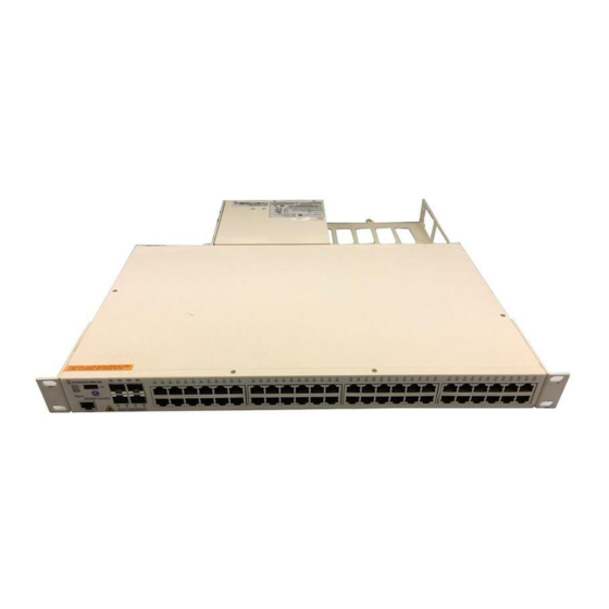
Page 63: Omniswitch 6800-48L Front Panel
The OS6800-48L provides four combo SFP slots for 1000Base-X high- speed connections. By default, when an SFP is installed in a combo port, it takes over the port Status and Slot Indicator LEDs number of the corresponding RJ-45 Ethernet port. In other words, if an SFP... -
Page 64: Omniswitch 6800 Series Leds
Displays 0 when the switch is booting. Blinks 1–8 if the switch is The left-hand LED is the data speed LED. The right-hand LED is the in pass-through mode. link/activity status LED. Ports 1–24 on OS6800-U24 switches have a single speed LED. -
Page 65: Omniswitch 6800 Series Rear Panel
OmniSwitch 6800 Series Rear Panel Stacking Ports A and B Power Connector Socket Type IEC-320-C13. Connector ports for use in stacking OmniSwitch 6800 Series switches into Supports one 10 amp power cord. OmniSwitch a virtual chassis. For detailed information on stacking switches, refer to... -
Page 66: User Documentation On Cd
Guide following manuals: Includes procedures for readying a switch for integra- OmniSwitch 6800 Series Getting Started Guide tion into a network. Topics include the software direc- • tory architecture, image rollback protections, Describes the hardware and software procedures for authenticated switch access, managing switch files,... - Page 67 OmniSwitch 6800/6850/9000 Advanced Routing To load the CD and access the user documentation, refer to the • Configuration Guide instructions printed on the CD packaging. Includes network configuration procedures and descrip- All documentation is in format and requires the Adobe tive information on all the software features and proto- Acrobat Reader program for viewing.
- Page 68 User Documentation on CD October 2006...