Table of Contents
Advertisement
Quick Links
Advertisement
Table of Contents

Related Manuals for Alcatel OS-6124


Summary of Contents for Alcatel OS-6124
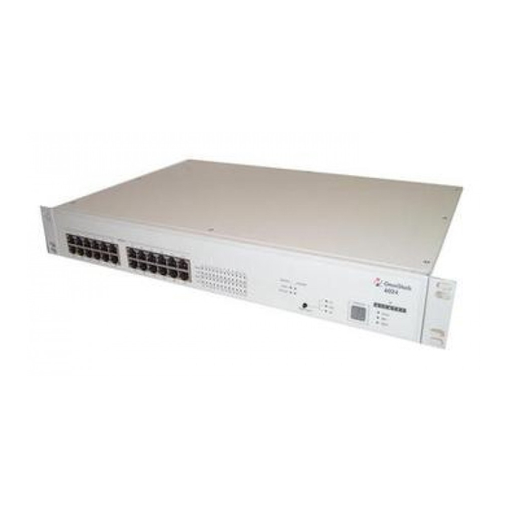
- Page 1 Part No. 060143-10, Rev. A January 2002 OmniStack 6124 ® Getting Started Guide...
- Page 2 Additionally, with 24-hour-a-day access to Alcatel’s Service and Support web page, you’ll be able to view and update any case (open or closed) that you have reported to Alcatel’s technical support, open a new case or access helpful release notes, technical bulletins, and manuals.
- Page 3 Operation of this equipment in a residential area is likely to cause interference, in which case the user will be required to correct the interference at his own expense.
-
Page 5: Table Of Contents
Installing Optional Media and Stacking Modules Connecting Stacking Modules across Multiple Switches Installing a GBIC Transceiver Connecting the Switch System Making a Connection to an RJ-45 Port Connecting to a 100BASE-FX Port Connecting to a Gigabit Fiber Optic Port Connecting to a 1000BASE-T Port... - Page 6 CE Mark Declaration of Conformance for EMI and Safety (EEC) Safety Compliance Warning: Fiber Optic Port Safety Avertissment: Ports pour fibres optiques - sécurité sur le plan optique Warnhinweis: Faseroptikanschlüsse - Optische Sicherheit Underwriters Laboratories Inc. (USA) Wichtige Sicherheitshinweise (Germany)
-
Page 7: Introduction
• Configurable broadcast storm control • Port mirroring (for real-time debugging without affecting the target port) • Port trunking (up to 5 trunks per switch or 12 trunks for the entire stack, each trunk contains 2~4 ports) * This feature is not supported in the current firmware release. -
Page 8: Installing The Switch
A Management Module can be installed in the upper slot on the rear panel (see page 3). The lower-left slot can be used for an optional media expansion module or Stacking Module, while the lower-right slot can be used for a media expansion module. -
Page 9: Mounting The Switch
• Power requirements: 100 to 240 VAC (± 10%) at 50 to 60 Hz (± 3 Hz). The switch’s power supply automatically adjusts to the input voltage level. • The switch should be located in a cool dry place, with at least 10 cm (4 in.) of space on the sides for ventilation. -
Page 10: Mounting Switches In A Rack
If you install a backup Management Module, it will automatically take over from the master should it fail. The switch with the lowest stack unit ID will always act as the master agent. For more information on switch management and the fail-over process, see the OS-6124 Users Guide. -
Page 11: Installing Optional Media And Stacking Modules
Installing the Switch Installing Optional Media and Stacking Modules The two lower slots on the rear panel of the switch are provided for various optional media expansion modules (100BASE-FX or Gigabit) or Stacking Modules. The 100BASE-FX fiber optic module can be used to connect to remote sites, and a Gigabit module can be used as a network backbone. -
Page 12: Installing A Gbic Transceiver
This port can be connected to a site up to 220 m (722 ft) away with 62.5/125 micron multimode fiber cable, or up to 500 m (1641 ft) with 50/125 micron multimode fiber cable. -
Page 13: Connecting The Switch System
RJ-45 port on the switch. All RJ-45 ports support 10 Mbps and 100 Mbps Ethernet connections. When inserting an RJ-45 plug, be sure the tab on the plug clicks into position to ensure that it is properly seated. Using the switch in a stand-alone configuration, you can network up to 24 end nodes. -
Page 14: Connecting To A 100Base-Fx Port
If you use an SC-to-ST converter, run cable from the Rx (Tx) port on the module to the Tx (Rx) port on the target device. Note that the fiber optic ports operate only at 100 Mbps, full duplex. In this mode, you can run a fiber optic link up to 2 kilometers (1.24 miles). -
Page 15: Connecting To A 1000Base-T Port
100m (328 feet). You should test the cable installation for IEEE 802.3ab compliance. See “1000BASE-T Cable Requirements” on page 18. Note that this module operates at 10, 100 or 1000 Mbps with support for auto-negotiation of duplex mode (full/half), speed, and flow control. -
Page 16: Powering On The Switch
“DC INPUT” receptacle on the rear of the switch.) Check the LED marked Power on the front panel to see if it is on. The unit will automatically select the setting that matches the connected input voltage. -
Page 17: Verifying System Operation
(such as a workstation or server). When a port on the switch is connected to a hub (a 10 or 100 Mbps repeater), the bandwidth provided by that port is shared by all the devices connected to the attached hub. - Page 18 Flexible Configuration - This switch is not only designed to segment your network, but also to provide a wide range of options in setting up network connections. It can be used as a simple stand-alone switch; stacked up to four high; or connected with standard repeater hubs, switches, or other network interconnection devices in various configurations.
-
Page 19: Product Specifications
440 x 285 x 64 mm (17.37 x 11.22 x 2.53 in.) Weight 4.5 kg (9.92 lb) Input Power Full range: 100 to 240 V (±10%), 50 to 60 Hz (±3 Hz) Maximum Current 0.80 A max.@110 V, 0.50 A max.@240 V... -
Page 20: Modules
OmniStack 6124 ® Modules Management Module (OS-6124-MNGT-KIT) System Configuration Configuration via console connection to serial port or via Telnet; Web-based management via HTTP protocol to access embedded management program; Full-featured SNMP/RMON management using network management software Management Agent MIB support: MIB II (RFC1213), Bridge MIB (RFC 1493), Ethernet-like MIB (RFC1643), RMON MIB (RFC1757), and Alcatel ’s private MIB... -
Page 21: 1000Base-Lx Module (Os-6Gsm-Fs-1)
SCSI Type 4, length 1 m Backplane Bandwidth 9.6 Gbps Troubleshooting Diagnosing Switch Indicators The switch can be easily monitored through panel indicators to assist the network manager in identifying problems. This table below describes common problems you may encounter and possible solutions. -
Page 22: Power And Cooling Problems
Alcatel distributor. Power and Cooling Problems If the power indicator does not turn on when the power cord is plugged in, you may have a problem with the power outlet, power cord, or internal power supply as explained in the previous section. However, if the unit powers off after running for a... -
Page 23: Port And Cable Assignments
Not Used Not Used Straight-Through Wiring If the twisted-pair cable is to join two ports and only one of the ports has an internal crossover (MDI-X), the two pairs of wires must be straight-through. Straight-Through RJ-45 Pin Assignments End 1... -
Page 24: 1000Base-T Pin Assignments
Category 5. Therefore, the first step in preparing existing Category 5 cabling for running 1000BASE-T is a simple test of the cable installation to be sure that it complies with the IEEE 802.3ab standards. -
Page 25: Emi Certification
It has been tested and found to comply with the limits for a Class A digital device pursuant to Subpart B of Part 15 of FCC Rules, which are designed to provide reasonable protection against such interference when operated in a commercial environment. -
Page 26: Ce Mark Declaration Of Conformance For Emi And Safety (Eec)
(>95% Reduction @10 ms, 30% Reduction @500 ms, >95% Reduction @5000 ms) LVD: • EN 60950 (A1/1992; A2/1993; A3/1993; A4/1995; A11/1997) Warning! Do not plug a phone jack connector in the RJ-45 port. This may damage this device. Les raccordeurs ne sont pas utilisé pour le système téléphonique! -
Page 27: Safety Compliance
When using a fiber optic media expansion module, never look at the transmit laser while it is powered on. Also, never look directly at the fiber TX port and fiber cable ends when they are powered on. Avertissment: Ports pour fibres optiques - DISPOSITIF LASER sécurité... -
Page 28: Wichtige Sicherheitshinweise (Germany)
Die Netzanschlu ßsteckdose soll nahe dem Gerät angebracht und leicht zugänglich sein. Das Gerät ist vor Feuchtigkeit zu schützen. Bei der Aufstellung des Gerätes ist auf sicheren Stand zu achten. Ein Kippen oder Fallen könnte Beschädigungen hervorrufen. Die Belüftungsöffnungen dienen der Luftzirkulation, die das Gerät vor Überhitzung schützt. - Page 30 150200004400A E012002-R01...