Table of Contents
Advertisement
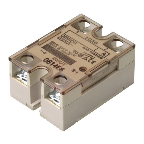
Solid State Relays
G3NA
The reliable choice for Hockey-puck-style
Solid State Relays. Available in a Wide
Range of Currents.
• All models feature the same compact dimensions to provide a
uniform mounting pitch.
• Built-in varistor effectively absorbs external surges.
• Operation indicator enables monitoring operation.
• Protective cover for greater safety.
• Certified by UL, CSA, and TÜV.
Model Number Structure
■ Model Number Legend
G3NA-@@@@@-@
2 3 4 5 6
7
1
1. Basic Model Name
G3NA:
Solid State Relay
2. Load Power Supply
Blank:
AC output
D:
DC output
3. Rated Load Power Supply Voltage
2:
200 VAC or 200 VDC
4:
400 VAC
4. Rated Load Current
Note: Not all combinations of current and voltage are available.
05:
5 A
10:
10 A
20:
20 A
25:
25 A
40:
40 A
50:
50 A
75:
75 A
90:
90 A
5. Terminal Type
B:
Screw terminals
6. Zero Cross Function
Blank:
Equipped with zero cross function
(AC-output models only)
7. Certification
Blank:
Models certified by UL and CSA
UTU:
Certified by UL, CSA, and TÜV
Solid State Relays
G3NA
1
Advertisement
Table of Contents

Related Manuals for Omron G3NA


Summary of Contents for Omron G3NA
- Page 1 The reliable choice for Hockey-puck-style Solid State Relays. Available in a Wide Range of Currents. • All models feature the same compact dimensions to provide a uniform mounting pitch. • Built-in varistor effectively absorbs external surges. • Operation indicator enables monitoring operation.
- Page 2 *All models are certified by UL, CSA, and TÜV. Note: 1. The applicable output load depends on the ambient temperature. Refer to Load Current vs. Ambient Temperature in Engineering Data. 2. Loss time increases under 75 VAC. (Refer to page 13.) Confirm operation with the actual load.
-
Page 3: Specifications
G3NA-490B-UTU G3NA-D210B-UTU Note: 1. The input impedance is measured at the maximum value of the rated supply voltage (for example, with the model rated at 100 to 120 VAC, the input impedance is measured at 120 VAC). 2. With constant current input circuit system. - Page 4 2,500 VAC, strength 50/60 Hz for 1 min Vibration Destruction: 10 to 55 to 10 Hz, 0.75-mm single amplitude (1.5-mm double amplitude) resistance Shock Destruction: 1,000 m/s resistance Operating: –30 ° C to 80 ° C (with no icing or condensation) Ambient Storage: –30 °...
- Page 5 60 70 60 70 Ambient temperature (°C) Ambient temperature (°C) Ambient temperature (°C) Note: The ambient operating temperature of the Y92B-P250NF is − 30 to 70 ° C. Be sure the operating temperature is within this range. G3NA Solid State Relays...
- Page 6 One Cycle Surge Current The values shown by the solid line are for non-repetitive inrush currents. Keep the inrush current below the values shown by the dotted line if it occurs repetitively. G3NA-210B-UTU G3NA-220B-UTU G3NA-240B-UTU/250B-UTU G3NA-410B-UTU G3NA-425B-UTU G3NA-450B-UTU G3NA-205B-UTU 1,000...
- Page 7 26 max. Two, M4 x 8 screws 28 max. Input 43 max. G3NA-D210B-UTU Note: The load can be connected to either the positive or negative side. Four, M4 x 8 11.9 Mounting Holes Terminal Arrangement/ screws 4.5 dia. Internal Connections (Top View) Two, 4.3-dia.
- Page 8 Y92B-N50 Heat Sink (for the G3NA-205B-UTU, G3NA-210B-UTU, G3NA-410B-UTU, G3NA-D210B-UTU) For surface mounting, a 30% derating of the load current is required (from the Load Current vs. Ambient Temperature graphs). The orientation indicated by the external dimensions is not the correct mounting orientation. When opening mounting holes, refer to the mounting hole dimensions.
- Page 9 Y92B-N100 Heat Sink (for the G3NA-220B-UTU, G3NA-425B-UTU) For surface mounting, a 30% derating of the load current is required (from the Load Current vs. Ambient Temperature graphs). The orientation indicated by the external dimensions is not the correct mounting orientation. When opening mounting holes, refer to the mounting hole dimensions.
- Page 10 Four, 4.3-dia. or M4 holes For surface mounting, a 30% derating of the load current is required (from the Load Current vs. Ambient Temperature graphs). The orientation indicated by the external dimensions is not the correct mounting orientation. When opening mounting holes, refer to the mounting hole dimensions.
-
Page 11: Safety Precautions
7. Do not transport the G3NA under the following conditions. Failure • Do not use the G3NA if the heat sink fins are bent, e.g., as the or malfunction may occur. - Page 12 • Do not use or store in locations subject to exposure to water, oil, or chemicals. Ventilation Outside the Control Panel • Do not use or store in locations subject to high temperatures or high humidity.
- Page 13 Be sure that this does not cause any problems. Loss time Using DC Loads For a DC or L load, a diode should be connected in parallel the load to absorb the counter electromotive force of the load. Load...
- Page 14 Therefore, always turn OFF the power tight, the G3NA will be damaged by heat generated when the power to the input or load and check that it is safe before replacing or wiring is ON. Perform wiring using the specified tightening torque.
- Page 15 G3NA Solid State Relays...
- Page 16 Warranty and Limitations of Liability WARRANTY OMRON's exclusive warranty is that the products are free from defects in materials and workmanship for a period of one year (or other period if specified) from date of sale by OMRON. OMRON MAKES NO WARRANTY OR REPRESENTATION, EXPRESS OR IMPLIED, REGARDING NON-INFRINGEMENT, MERCHANTABILITY, OR FITNESS FOR PARTICULAR PURPOSE OF THE PRODUCTS.