Omron ACCURAX G5 SERVO DRIVE Datasheet
Servo drive
Hide thumbs
Also See for ACCURAX G5 SERVO DRIVE:
- System configuration manual (14 pages) ,
- User manual (553 pages) ,
- Quick start manual (13 pages)
Advertisement
Table of Contents
R88D-KN@@@-ML2, R88D-KT@
Accurax G5 servo drive
Accurate motion control in a compact size
servo drive family. MECHATROLINK-II
motion bus and safety built-in.
• MECHATROLINK-II and Analog/ Pulse servo drive
models
• Safety conforming ISO13849-1 Performance Level
D
• High-response frequency of 2 kHz
• High resolution serial encoder for greater accuracy
provided by 20 bits encoder
• External encoder input for full close loop
• Real time auto-tuning
• Advanced tuning algorithms (Anti-vibration function,
torque feedforward, disturbance observer)
Ratings
• 230 VAC Single-phase 100 W to 1.5 kW (8.59 Nm)
• 400 VAC three-phase 600 W to 5 kW (28.7 Nm)
System configuration
MECHATROLINK-II control
TJ1-MC04/16
R88D-KN
Encoder cable
Power cable
Servo Motor
3000 rpm (50 W-5 kW)
Servo Motor
2000 rpm (400 W-5 kW)
Servo Motor
1000 rpm (900 W-3 kW)
Accurax G5 servo drive
CJ1W-MCH72
CJ1W-NCF71
MECHATROLINK-II
-ML2
Open Analog/pulse control
Accurax G5 Analog/pulse
Servo Drive
Power cable
Encoder cable
R88D-KT
Personal computer
software: CX-One
Accurax G5 ML-II Servo Drives
R88D-KN
-ML2
Motion control unit
General purpose cable
Terminal block
for Servo drive I/O
general purpose
signals
Unit
Terminator
Personal computer:
Software CX-One
Position control unit
61
Advertisement
Table of Contents

Related Manuals for Omron ACCURAX G5 SERVO DRIVE


Summary of Contents for Omron ACCURAX G5 SERVO DRIVE
-
Page 1: System Configuration
• Real time auto-tuning • Advanced tuning algorithms (Anti-vibration function, torque feedforward, disturbance observer) Ratings • 230 VAC Single-phase 100 W to 1.5 kW (8.59 Nm) • 400 VAC three-phase 600 W to 5 kW (28.7 Nm) System configuration MECHATROLINK-II control... -
Page 2: Type Designation
Servo motor supported Accurax G5 rotary servo motor Accurax G5 servodrive Voltage Speed Rated torque Capacity Model MECHATROLINK-II model Analog/Pulse model 230V 400V 230V 400V 230 V 3000 min 0.16 Nm 50 W R88M-K05030(H/T)-@ R88D-KN01H-ML2 R88D-KT01H 0.32 Nm 100 W... -
Page 3: Servo Drive Specifications
Input power Main circuit Single-phase/3-phase, 200 to 240 VAC + 10 to -15% (50/60 Hz) Supply Control circuit Single-phase, 200 to 240 VAC + 10 to -15% (50/60 Hz) Control method IGBT-driven PWM method, sinusoidal drive Feedback Serial encoder (incremental/absolute value) Usage/storage temperature 0 to +55°C / -20 to 65°C... - Page 4 Sequence output signal It is possible to output three types of signal form incl.: brake release, servo ready, servo alarm, positioning com- plete, motor rotation speed detection, torque limit detection, zero speed detection, speed coincidence detection, warning, position command status, speed limit detection, alarm ouput, speed command status.
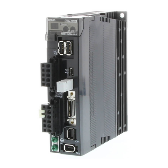
- Page 5 MECHATROLINK-II servo drives Analog/pulse servo drives Note: the above pictures show 230 V servo drives models only. The 400 V servo drives have 24 VDC power input terminals for control circuit instead of L1C and L2C terminals. Accurax G5 servo drive...
- Page 6 External latch input 1 SI-MON0 General purpose monitor input 0 BTP-I Connecting pin for the absolute encoder backup battery. Do not connect when a battery is connected to the encoder cable (CN2 connector). BTN-I Terminals not used. Do not connect.
- Page 7 Reverse torque limit input: ±10 V/rated motor torque (input gain can be modified using a parameter). AGND1 Analog signal ground Common +24 VIN Control power supply input for sequence signals: users must provide the +24 V power supply (12 to 24 V). Servo ON: this turn ON the servo. Position/Full DFSEL1 Vibration filter switching 1 Enables vibration filter according parameter setting.
- Page 8 Positioning complete output 1: turns ON when position error is equal to setting parameter. Full close loop INP1COM INP2 Position complete output 2 The function of output signals allocated to pins 11,10, 34 to 39 can be changed with these op- tions by parameters settings. P-CMD Position command status...
- Page 9 Pin No. Signal name Function Not used. Do not connect. SF1- Safety input 1 & 2. This input turns OFF the power trransistor drive signals in the servo drive to cut off the current output to the motor. SF1+ SF2- SF2+ EDM- A monitor signal is output to detect a safety function failure.
- Page 10 170 (for Analog/pulse model) 86 (for ML2 model) 172 (for ML2 model) φ5.2 ±0.5 (85) R88D-KT06/10/15F, R88D-KN06/10/15F-ML2 (400 V, 600 W - 1.5 kW) 170 (for Analog/pulse model) 172 (for ML2 model) 91 (for Analog/pulse model) 92 (for ML2 model) φ5.2 ±0.5...
- Page 11 R88D-KT30/50F, R88D-KN30/50F-ML2 (400 V, 3 - 5 kW) 212 (for Analog/pulse model) φ5.2 213 (for ML2 model) ±0.5 φ5.2 R2.6 ±0.5 R2.6 (130) φ5.2 Filters Filter model External dimensions Mount dimensions R88A-FIK102-RE R88A-FIK104-RE R88A-FIK107-RE drive R88A-FIK114-RE mounts R88A-FIK304-RE R88A-FIK306-RE R88A-FIK312-RE...
-
Page 12: Installation
Maximum output current: 50 mADC) SF2- *1 For servo drives from 750 W, B2 and B3 are short-circuited. If the internal regenerative resistor is insufficient, remove the wire between B2 and B3 and connect an external regenerative resistor between B1 and B2. - Page 13 B1 and B2. *2 For use only with an absolute encoder. If a backup battery is connected to CN1 I/O connector, an encoder cable with a battery is not required. *3 Wiring diagram example using the G9SX safety unit. If a safety unit is not used, keep the factory safety bypass connector installed in the CN8.
- Page 14 Shell SF2- *1 For servo drives from 750 W, B2 and B3 are short-circuited. If the internal regenerative resistor is insufficient, remove the wire between B2 and B3 and connect an external regenerative resistor between B1 and B2. *2 For use only with an absolute encoder. If a backup battery is connected to CN1 I/O connector, an encoder cable with a battery is not required.
- Page 15 *5 Wiring diagram example using the G9SX safety unit. If a safety unit is not used, keep the factory safety bypass connector installed in the CN8. Note: The input function of pins 8,9 and 26 to 33, and output function of pins 10, 11, 34, 35, 38 and 39, can be changed via parameter settings.
-
Page 16: Ordering Information
... show the recommended sequence to select the components in Accurax G5 servo system Servo motors, power & encoder cables Note: Refer to the Accurax G5 servo motor chapter for servomotor, motor cables or connectors selection Servo drives Symbol Specifications... - Page 17 Connectors Specifications Model External encoder connector (for CN4) R88A-CNK41L Safety I/O signal connector (for CN8) R88A-CNK81S Computer software Specifications Model Configuration and monitoring software tool for servo drives and inverters. (CX-drive version 1.91 or higher) CX-drive Accurax G5 servo drive...
- Page 18 ... show the recommended sequence to select the components in Accurax G5 servo system Servo motors, power & encoder cables Note: Refer to the Accurax G5 servo motor chapter for servomotor, motor cables or connectors selection Servo drives Symbol Specifications...
- Page 19 CJ1W-NC414 Terminal block cable for external signals Position control units (high-speed type) 0.5 m XW2Z-C50X (for input common, forward/reverse run prohibited inputs, CJ1W-NC234 XW2Z-100X emergency stop input, origin proximity input and interrupt in- CJ1W-NC434 XW2Z-200X put) CJ1W-NC214 XW2Z-300X CJ1W-NC414 XW2Z-500X...
- Page 20 Configuration and monitoring software tool for servo drives and inverters. (CX-drive version 1.90 or higher) CX-drive ALL DIMENSIONS SHOWN ARE IN MILLIMETERS. To convert millimeters into inches, multiply by 0.03937. To convert grams into ounces, multiply by 0.03527. In the interest of product improvement, specifications are subject to change without notice. Cat. No. I101E-EN-01A...