Advertisement
Quick Links
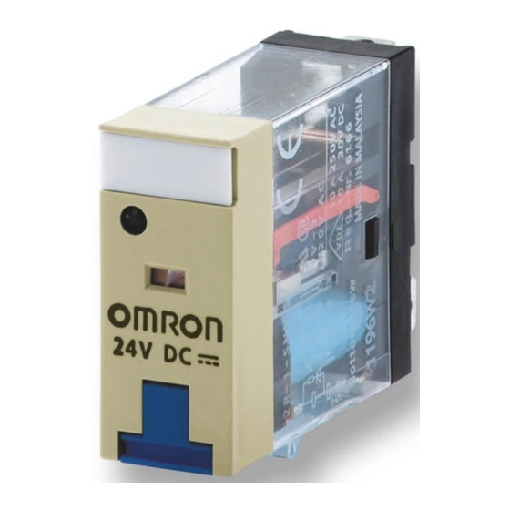
General-purpose Relay
G2RS
Slim and Space-saving Power Plug-in Relay
• Lockable test button models now available.
• Built-in mechanical operation indicator.
• Provided with nameplate.
• AC type is equipped with a coil-disconnection self-diagnostic
function (LED type).
• High switching power (1-pole: 10 A).
• Environment-friendly (Cd, Pb free).
• Wide range of Sockets also available.
Model Number Structure
Model Number Legend
G2R
-
-
1
2
3
4
5
1. Relay Function
Blank:
General-purpose
2. Number of Poles
1:
1 pole
2:
2 poles
3. Contact Form
Blank:
SPDT
4. Contact Type
Blank:
Single
Ordering Information
List of Models
Classification
Plug-in terminal
General-purpose
LED indicator
LED indicator with test button
Diode
LED indicator and diode
LED indicator and diode with test button
Note: When ordering, add the rated coil voltage and "(S)" to the model number. Rated coil voltages are given in the coil ratings table.
Example: G2R-1-S 12 VDC (S)
-
6
7
Unsealed
New model
Rated coil voltage
5. Terminals
S:
Plug-in
6. Classification
Blank:
General-purpose
N:
LED indicator
D:
Diode
ND:
LED indicator and diode
NI:
LED indicator with test button
NDI:
LED indicator and diode with test button
7. Rated Coil Voltage
Enclosure
Coil ratings
rating
AC/DC
DC
General-purpose Relay
LR
Contact form
SPDT
DPDT
G2R-1-S
G2R-2-S
G2R-1-SN
G2R-2-SN
G2R-1-SNI
G2R-2-SNI
G2R-1-SD
G2R-2-SD
G2R-1-SND
G2R-2-SND
G2R-1-SNDI
G2R-2-SNDI
G2RS
G-5
Advertisement

Related Manuals for Omron G2RS


Summary of Contents for Omron G2RS
- Page 1 LED indicator and diode with test button G2R-1-SNDI G2R-2-SNDI Note: When ordering, add the rated coil voltage and "(S)" to the model number. Rated coil voltages are given in the coil ratings table. Example: G2R-1-S 12 VDC (S) New model...
-
Page 2: Specifications
43.2 mA 0.98 2.35 24 V 21.6 mA 1,113 3.60 8.25 48 V 11.4 mA 4,220 15.2 29.82 * The rated current and coil resistance are measured at a coil temperature of 23°C with tolerances of ±10%. G2RS General-purpose Relay... -
Page 3: Contact Ratings
5% to 85% Weight Approx. 21 g Note: Values in the above table are the initial values. *4,000 VAC, 50/60 Hz for 1 minute when the P2R-05A or P2R-08A Socket is mounted. Approved Standards UL 508 (File No. E41643) IEC/VDE (EN61810) -
Page 4: Engineering Data
Switching current (A) Switching current (A) Ambient Temperature vs Maximum Coil Voltage DC coil AC coil Note: The maximum voltage refers to the maximum value in a varying range of operating power voltage, not a continuous voltage. Ambient temperature ( C) G2RS... - Page 5 Typical information for reference only The following data is provided as experimental and/or calculated data for reference only. These fall under the category of typical behaviour and the operation of individual relays will vary according to the exact operating conditions...
- Page 6 Dimensions Note: All units are in millimeters unless otherwise indicated. Relays with Plug-in Terminals SPDT Relays G2R-1-S, G2R-1-SN, G2R-1-SNI Terminal Arrangement/Internal Connections G2R-1-SD, G2R-1-SND, G2R-1-SNDI (Bottom View) G2R-1-SD (DC) G2R-1-S 29 max. 13 max. G2R-1-SN, G2R-1-SNI (DC) G2R-1-SN, G2R-1-SNI (AC) 4.75...
- Page 7 (3.4) 22.6 A1 A2 Option (with ejector Standard model and label attached) (5.3) 28.6 18.0 max. 32.6 Accessories for P2RF-@-S Socket Bridge Clip and Release Lever Insulating coating 16.8 40.35 1.2 dia. conductor (See note 1.) G2RS G-11 General-purpose Relay...
- Page 8 3.5-dia. hole M3 or 3.5-dia. (A1) hole (A2) 11.5 61 max. 16.0 max. Note: Pin numbers in parentheses apply to DIN standard. P2RF-08-E P2RF-08-E Terminal Arrangement Mounting Holes (Top View) (for Surface Mounting) Eight, M3 8 48.0 max. (21) (11) 3.2-dia.
- Page 9 Mounting Height of Relay with DIN-rail/Surface Mounting Sockets P2RF-@-E P2RF-@ 62.0 66.5 67.0 70.5 P2RF-@-S 72.0 65.0 28.6 (5.30) Back-connecting Sockets Terminal Arrangement Mounting Holes P2R-05P (1-pole) (Bottom View) 14.5 max. Tolerance: 0.1 Five, 1.6-dia. holes 35.5 max. 36.5 max.
- Page 10 36.5 max. Terminal plate thickness: 0.3 30.5 0.2 P2R-08A (2-pole) 14.5 max. 35.5 max. Recommended thickness of the panel is 1.6 to 2.0 mm Eight, 3 x 1.2-dia. holes Terminal plate thickness: 0.3 36.5 max. P2R-057P Terminal Arrangement Mounting Holes 14 max.
-
Page 11: End Plate
Use an insulated tool when you operate the test button. Precautions for P2RF-@-S Connection • Do not move the screwdriver up, down, or from side to side while it is inserted in the hole. Doing so may cause damage to internal components (e.g., deformation of the clamp spring or cracks in the... - Page 12 ALL DIMENSIONS SHOWN ARE IN MILLIMETERS. To convert millimeters into inches, multiply by 0.03937. To convert grams into ounces, multiply by 0.03527. Cat. No. J140-E2-01A In the interest of product improvement, specifications are subject to change without notice. G2RS G-16...