Omron F150-3 - MANUAL 1 Setup Manual
Vision sensor
Hide thumbs
Also See for F150-3 - MANUAL 1:
- Datasheet (15 pages) ,
- Operation manual (363 pages) ,
- Operation (7 pages)
Table of Contents
Advertisement
Quick Links
Download this manual
See also:
Operating Manual
Advertisement
Chapters
Table of Contents

Related Manuals for Omron F150-3 - MANUAL 1


Summary of Contents for Omron F150-3 - MANUAL 1
- Page 1 Cat. No. Z141-E1-02B F150-3 Vision Sensor Manual 1: SETUP MANUAL...
- Page 2 F150-3 Vision Sensor Setup Manual Revised March 2005...
- Page 3 The following are some examples of applications for which particular attention must be given. This is not intended to be an exhaustive list of all possible uses of the products, nor is it intended to imply that the uses listed may be suitable for the products: •...
- Page 4 EQUIPMENT OR SYSTEM. PERFORMANCE DATA Performance data given in this document is provided as a guide for the user in determining suitability and does not constitute a warranty. It may represent the result of OMRON’s test conditions, and the users must correlate it to actual application requirements. Actual performance is subject to the OMRON Warranty and Limitations of Liability.
- Page 6 Inc. OMRON, 2000 All rights reserved. No part of this publication may be reproduced, stored in a retrieval system, or transmitted, in any form, or by any means, mechanical, electronic, photocopying, recording, or otherwise, without the prior written permission of OMRON.
-
Page 8: Table Of Contents
Connector ......Wiring....... . - Page 9 Console....... Cables ....... .
- Page 10 This manual describes the hardware for the F150 Vision Sensor and how to install the components, and it includes the sections described below. This is one of two manuals used to operate the F150.Refer to the following table for the con- tents of each manual.
-
Page 12: Precautions
F150 Vision Sensor. Safety Precautions ...... -
Page 13: Safety Precautions
ON or immediately after the power is turned OFF. These lights gen- erate heat and can cause burns. !Caution Do not use the F150 in environments with flammable or explo- sive gases. !Caution Install the F150 away from high-voltage equipment or motors to ensure safety during operation and maintenance. -
Page 14: General Precautions
OMRON representa- tive. Make sure that the ratings and performance characteristics of the product are sufficient for the systems, machines, and equipment, and be sure to provide the systems, machines, and equipment with double safety mechanisms. -
Page 16: Before Installing
1-1-4 Cables........ -
Page 17: Installation Precautions
F150-VS Camera Cable F150-KP Console 1-1-2 Installation Site Do not install the F150 in locations subject to the following conditions: Ambient temperatures outside of 0 to 40°C for the F300- M09 Video Monitor (recommended monitor) or outside of 0 to 50°C for all other F150 components... - Page 18 Installation Precautions Section 1-1 Do not install the Controller in the orientations shown in the following diagram. INCORRECT Ambient Temperature Maintain a minimum clearance of 50 mm above and below F150 components to improve air circulation. Do not install F150 components immediately above strong heat sources, such as heaters, transformers, or large-ca- pacity resistors.
-
Page 19: Cables
Always turn OFF the power before connecting or disconnect- ing cables. 1-1-5 Camera The Camera’s case is connected to the 0V line in the internal circuits. Heed the following precautions to prevent noise inter- ference. Do not ground the Camera. -
Page 20: Video Monitor
RESET Terminal Do not use RESET input immediately after power is turned ON. When using RESET input to synchronize execution tim- ing, wait at least 1 s after turning ON the F150 power supply before turning ON the RESET terminal. 1-1-10... -
Page 21: Confirming Package Contents
Confirming Package Contents Section 1-2 Confirming Package Contents Check the contents of the package as soon as you receive the F150. Contact the nearest OMRON representative if any of the following items are missing. F150-C10E-3 F150-C15E-3 F150 Vision Mate Controller... -
Page 22: Product Introduction
2-6-3 Extension Tubes ....... Lighting ........ -
Page 23: Overview Of F150 Application
Overview of F150 Application Section 2-1 Overview of F150 Application The following table shows the basic steps that must be per- formed to use the F150. Step Manual Setup Manual Unit Connections and Wiring Video Programmable Controller Monitor Power Supply... -
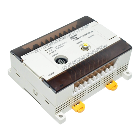
Page 24: Component Names And Functions
Component Names and Functions Section 2-2 Component Names and Functions The following diagram shows the terminals, connectors, and indicators on the F150-C10E-3 and F150-C15E-3 Vision Mate Controller. F150-C10E-3 F150-C15E-3 Ground Power supply Output Input terminal terminals terminals terminals POWER indicator... - Page 25 Component Names and Functions Section 2-2 F150-C10E3DRT The F150-C10E-3-DRT can operate as a CompoBus/D Slave. Ground Power supply Output Input terminal terminals terminals terminals POWER indicator Monitor connector indicator ERROR indicator RS-232C Console connector connector indicator Camera CompoBus/D indicator connector...
- Page 26 Wired to the power supply. Indicates the status of the network Ground Terminal in CompoBus/D communications. Wired to the ground. Lit in green when the network is op- Input Terminals erating normally. Wired to external devices, such as DIP Switch...
-
Page 27: Connections
Connecting or disconnecting cables with power turned ON can damage peripheral devices. If the Two-camera Unit is connected, turn OFF the power to the Two-camera Unit as well as the power to the F150 itself before connecting or disconnecting cables. - Page 28 An F150-LT10A Light Source (with dedicated lens) is at- tached to the F150-S1A Camera. If the field of vision is too small or too big, use the F150- S1A Camera with a normal CCTV lens and light source.→ p. 20...
-
Page 29: Power Supply And Ground
(Provided with Two-camera Unit) Power Supply and Ground Wire the power supply and the ground to the top terminal block, and tighten the screws to a torque of between 0.5 and 0.6 N⋅m. After wiring, confirm that wiring and screw tightening have been performed properly. -
Page 30: Protective Conductor (Earth) Wiring
F150 operation or result in damage to F150 compo- nents. • To avoid damage to the equipment, do not share the pro- tective conductor wiring with any other devices nor wire the protective conductor terminal to the girder. Be sure to wire the protective conductor of the equipment indepen- dently. - Page 31 Wire the Power Supply Unit independently of other devic- es. In particular, keep the power supply wired separately from inductive loads. Keep the power supply cable as short as possible (less than 10 m). If UL recognition is required, use a UL class II power sup- ply.
-
Page 32: Cameras With Light Sources
A dedicated lens and light source have been attached to the F150 Camera (F150-S1A) to produce “Cameras with Light Sources.” The Light Source and Lens are a single unit and are thus compact and easy to mount. Cameras with F150-LT10A Light Source The F150-S1A Cameras are shipped with a Lens and Light Source attached. - Page 33 Cameras with Light Sources Section 2-5 Distance from Measurement Object The Camera must be mounted at a distance from the mea- surement object where it can correctly view the object. Note The Lens focus is fixed and the distance must be adjusted each time the Lens or Camera is changed because the field of vision and focus vary from Lens to Lens.
- Page 34 F150-SLC50 Camera distance Measurement 16.5 to 26.5 mm object Field of Vision 50 ✕ 50 mm If the object size and field of vision are incompatible, attach a standard CCTV lens and light source to the Camera. → p. 20...
-
Page 35: Cctv Lens
CCTV Lens When using a F150-S1A Camera (without a light source), refer to the following graph to select the appropriate Lens and Extension Tube. The lens will differ depending on the size of the measurement object and the distance from the Camera. - Page 36 CCTV Lens Section 2-6 The X axis of the graph shows field of vision L (mm), and the Y axis shows the camera distance A (mm). The curves on the graph indicate different lenses, and the “t” values indicates the lengths of the Extension Tubes.
-
Page 37: Lens
Extension Tubes One or more Extension Tubes are inserted between the lens and the Camera to focus the Camera image. Use a combina- tion of one or more of the six sizes of tube to achieve the required length. Note Do not use the 0.5-mm and 1.0-mm Extension Tubes at-... -
Page 38: Lighting
20 mm 10 mm 5 mm 1.0 mm 0.5 mm Lighting A stable image must be obtained to ensure accurate inspec- tion. Use appropriate lighting for the application and the mea- surement object if using the F150-S1A Camera. 2-7-1 Lighting Methods... - Page 39 Light is shone uniformly on the measurement object. Applications: Surface inspections Camera Light source Measurement object Oblique Lighting Detection can be made utilizing the difference in regular and diffuse reflected light. Applications: Inspections for surface gloss Camera Light source Measurement object...
-
Page 40: Two-Camera Unit
Connecting to the Power Supply Use a 24-VDC power supply. Specifications of crimp terminals and cables are the same as those for the F150 Power Supply. → p. 14 Note If the F150 and the Two-camera Unit need to be started sequentially, turn ON the Two-camera Unit first and then turn ON the F150. -
Page 41: Connecting To Cameras
Two-camera Unit Section 2-8 2-8-3 Connecting to Cameras Connect to the Cameras using F150-VS Camera Cables. − 24 VDC F150-VA F150-VS Camera Unit Camera Cable Cable (15 cm) (3 m) (Provided with Two-camera Unit) F150-A20 Two-camera Unit F150-C10E-3 F150-C15E-3 F150-C10E-3-DRT... -
Page 42: Mounting The Controller
Mounting the Controller Section 2-9 Mounting the Controller The Vision Mate Controller can be mounted to DIN Track or a flat surface. 2-9-1 Mounting to DIN Track The Vision Mate Controller can be easily mounted to or removed from 35-mm DIN Track. -
Page 43: Mounting On A Flat Surface
Controller locks into place. Removing the Controller Use a screwdriver to pull the hook down and then pull out the Controller from the bottom. 2-9-2 Mounting on a Flat Surface Mount the Controller using the holes and dimensions shown in the following diagram. -
Page 44: Terminal Blocks
Specifications ....... . . Terminals........ -
Page 45: Crimp Terminals And Cables
Applicable wire size: Insulated wire of 1.31 to 1.65 mm (AWG16 to AWG15) Specifications !Caution Use a DC power supply with a safe extra low-voltage cir- cuit that prevents occurrences of high voltages in the power supplies for the terminal blocks. Input Specifications... -
Page 46: Terminals
COM OUT Load Load COM OUT Output terminal Note If UL recognition is required, use a UL class II power sup- ply. Terminals The terminals on the terminal blocks are assigned as shown in the following diagrams and tables. F150-C10E-3... - Page 47 Terminals Section 3-3 Top Terminals ✕ ✕ ✕ ✕ ✕ ✕ ✕ ✕ ✕ ✕ ✕ ✕ ✕ ✕ ✕ ✕ ✕ ✕ ✕ ✕ ✕ ✕ ✕ Name/Application Name/Application Error output BUSY GATE Not connected COM OUT (*1) For RUN, ERR,...
- Page 48 !Caution Do not input the RESET input immediately after turning ON the power. When using RESET input to synchronize execution timing, wait at least 1 s after turning ON the F150 power supply before turning ON the RESET termi- nal.
- Page 49 !Caution Do not input the RESET input immediately after turning ON the power. When using RESET input to synchronize execution timing, wait at least 1 s after turning ON the F150 power supply before turning ON the RESET termi- nal.
-
Page 50: Rs-232C Connection
Wiring ........ -
Page 51: Connector
RS (RTS) Request to Send CS (CTS) Clear to Send Not connected Not connected Not connected SG (GND) Signal ground The following plug and hood are recommended and are avail- able from OMRON. Model Model No. Plug XM2A-0901 Hood XM2S-0911... -
Page 52: Wiring
Signal name Signal name Shield Connections for RS/CS Control F150 External device Signal name Signal name Shield Note Pin numbers on the external device will depend on the device being connected. Refer to the manual for the device being connected. -
Page 53: Connection
Connection Section 4-3 Connection Align the connector with the socket and press the connector straight into place. Tighten the two screws on the edges of the connector. !Caution Always turn OFF the power supply before connecting or disconnecting cables. Peripheral devices can be damaged if connected or disconnected with the power supply turned Note Always tighten the connector screws. -
Page 54: Compobus/D Connections
I/O format. Overview ........ -
Page 55: Overview
Vision Sensor’s communications specifica- tions before registering the Master’s scan list. Refer to the Expert Menu Operation Manual for details on set- ting the Vision Sensor’s communications specifications and changing the I/O format. - Page 56 Overview Section 5-1 Programmable Controller (Master) Remote I/O communications See the diagram on the next page for details on the output and input areas. F150-C10E-3-DRT F150-C10E-3-DRT F150-C10E-3-DRT...
- Page 57 Overview Section 5-1 Output Area Write commands are directed to the F150 in this area. The number of bytes in the area depends upon the input mode (basic or expand) that is selected. Basic Only a few words are occupied.
- Page 58 Overview Section 5-1 Input Area The measurement results (execution results) from the F150 are output to this area. Word +0 Control output (2 bytes) Word +1 Judgement results output (2 bytes) Word +2 F150 status output (2 bytes) Word +3...
-
Page 59: Communications Specifications
These values are valid when thick cable is used for the trunk line. The maximum network length is 100 m max. when thin cable is used. Set the number of words in the Menu. Reset the entire net- work after changing these settings. -
Page 60: Dip Switch Settings
Node Address Setting (0 to 63) Set the node address in binary with pins 1 through 6. These pins have values of 1, 2, 4, 8, 16, and 32 (left to right). The node address is set to 0 when the Sensor is shipped. - Page 61 DIP Switch Settings Section 5-3 Baud Rate Setting (125K bps, 250K bps, or 500K bps) Pins 7 and 8 set the baud rate as shown in the following dia- grams. • 125K bps (factory setting) • 250K bps • 500K bps...
-
Page 62: Connector Pin Allocation
Refer to the CompoBus/D (DeviceNet) Operation Manual for details on assembling a communications cable. Note Turn OFF the power supply before connecting or discon- necting the cable. Peripheral devices may be damaged if the cable is connected or disconnected with the power... -
Page 63: Led Indicators
The NS indicator shows the status of network. The indicator will be lit green when the network is operating normally. Note The MS and NS indicators are lit in green or red. The sta- tus of these indicators (lit, flashing, or not lit) can be used to determine what error has occurred. - Page 64 Object Attribute 1 Vendor instance 2 Product type 3 Product code 4 Revision 5 Status (bits supported) Bit 0 and bit 10 6 Serial number Unique for each Unit 7 Product name F150-C10E-3 8 State Item DeviceNet service Parameter option...
- Page 65 Object Instance type Static I/O instance 1 Item Content Value (read) (write) Object Attribute 1 Number of Members in List No instance 1 2 Members List 3 Data Item DeviceNet service Parameter option Object Service 0E Get_Attribute_Single instance 1 10 Set_Attribute_Single...
- Page 66 Multi-vendor Applications Section 5-6 Connection Object (0x05) Object class Attribute Not supported Service Not supported Max. number of active connections Item Section Information Max. number of instances Object Instance type Explicit Message instance Production trigger Cyclic Transport type Server Transport class...
- Page 67 Parameter option Object Service 05 Reset instance 1 0E Get_Attribute_Single 10 Set_Attribute_Single Item Section Information Max. number of instances Object instance 2 Instance type Polled I/O Production trigger Cyclic Transport type Server Transport class Item ID content Value (read) (write) Object...
- Page 68 Multi-vendor Applications Section 5-6 Note Indicates the number of input bytes used by the Slave. The leftmost and rightmost bytes are reversed. (For example, the produced connection size = 4000 when 64 bytes are used.) Indicates the number of output bytes used by the Slave.
- Page 69 With the bit-strobed interface, the maximum produced connection size is 8 bytes. A produced connection size of 8 bytes (0800) will be used if a higher value has been set for the number of input bytes with the user MPU; the set value will be used if it is 8 bytes or less.
-
Page 70: Troubleshooting
Connection Errors ......Errors during Menu Operation .... -
Page 71: Connection Errors
The DIP switches on Intelligent Light Sources are not set correctly. When using the Two-camera Unit, set the Intelligent Light Source connected to Camera 0 to 0, and set the Intelli- gent Light Source connected to Camera 1 to 1. The Monitor image is not There is electrical noise entering from the power supply clear. -
Page 72: Rs-232C Communications Errors
Select Normal, Host link, or Menu operations under RS-232C/Operating mode. The Unit operates well initially, but The reception buffer on the external device (e.g., after a while there is no response from computer) is full. Check that settings allow the the F150. -
Page 73: Led Indicators (For F150-C10E-3-Drt)
Master. • Are the cable lengths (trunk and branch lines) within specifications? • Are any cables loose or broken? • Is there a terminator on each end of the trunk line? • Is there excessive noise in the net- work? -
Page 74: Maintenance
7-1-2 F150-SLC20/SLC50 ......Regular Inspections ...... -
Page 75: Maintenance Parts And Replacement
Remove the light cable from the slot in the camera base. Remove the two screws securing the Light Source. Remove the Light Source from the Camera. Remove the Lens from the camera mount. Note Follow these steps in the reverse order to mount the Lens and Light Source. -
Page 76: F150-Slc20/Slc50
Disconnect the light cable from the light connector on the back of the Camera. Remove the light cable from the slot in the camera base. Remove the two screws securing the Light Source. Remove the two screws securing the Light Source. -
Page 77: Regular Inspections
Regular Inspections Section 7-2 If an Intelligent Light Source is not used, the screws in step 4 will be too long for the holes in the Camera. Use two M2×3 screws. The screws in step 3 are not required. !Caution Do not disassemble the Lens. -
Page 78: Specifications
Cables ........ -
Page 79: F150 Vision Mate Controller
(with internal surge absorber removed) Leakage current 10 mA max. 1500 Vp–p; pulse width: 0.1 µ s / 1 µ s; rising time: 1 ns (pulse) Noise resistance Vibration resistance 10 to 150 Hz; half-amplitude: 0.5 mm; maximum acceleration:... - Page 80 (with internal surge absorber removed) Leakage current 10 mA max. 1500 Vp–p; pulse width: 0.1 µ s / 1 µ s; rising time: 1 ns (pulse) Noise resistance Vibration resistance 10 to 150 Hz; half-amplitude: 0.5 mm; maximum acceleration:...
-
Page 81: Cameras
Cameras Section 8-2 Cameras F150-SL20A/SL50A (Camera with an F150-LT10A Light Source) Unit: mm Mounting dimensions Two M4 holes with depth of 9 mm 1/4-20UNC with depth of 9 mm... - Page 82 Cameras Section 8-2 F150-SLC20 (Camera with F150-LTC20 Intelligent Light Source) Unit: mm Two M4 holes with Mounting dimensions depth of 10 mm 1/4-20UNC with depth of 10 mm...
- Page 83 Cameras Section 8-2 F150-SLC50 (Camera with F150-LTC50 Intelligent Light Source) Unit: mm Mounting dimensions Two M4 holes with depth of 10 mm 1/4-20UNC with depth of 10 mm F150-S1A Camera Unit: mm F150 light connector C mount F150 connector Two M4 holes with...
- Page 84 8 minutes each in 3 directions Shock 150 m/s , 3 times each in 6 directions resistance Operating: 0 to 50 ° C; storage: –25 to +65 ° C Ambient temperature (with no icing or condensation) Ambient Operating/storage: 35% to 85% (with no condensation)
-
Page 85: Two-Camera Unit
, 10 times for 8 minutes each in 3 directions Shock resistance 150 m/s , 3 times each in 6 directions Operating: 0 to 50 ° C; storage: –25 to +65 ° C Ambient temperature (with no icing or condensation) Ambient humidity... - Page 86 (*: Light quantity can be controlled from the Controller.) Connectable Controllers F150-C10E-3, F150-C15E-3, F150-C10E-3-DRT Image memory Two sets (one for Camera 0 and the other for Camera 1) Image reading Simultaneous reading from two Cameras (preventing mutual light interference when using F150-SL20A/SL50A/SLC20/...
-
Page 87: Console
SHIFT 2000 Item Specification Vibration resistance 10 to 150 Hz; half-amplitude: 0.15 mm, 4 times for 8 min- utes each in 3 directions Shock resistance 196 m/s , 3 times each in 6 directions Operating: 0 to 50 ° C; storage: –25 to +65 ° C... - Page 88 Cables Section 8-5 Item Specification Vibration resistance 10 to 150 Hz; half-amplitude: 0.15 mm, 4 times for 8 min- utes each in 3 directions Shock resistance 196 m/s , 3 times each in 6 directions Operating: 0 to 50 ° C; storage: –25 to +65 ° C...
-
Page 89: Video Monitor
10 to 100 Hz; double-amplitude of 2 mm or acceleration of 19.6 m/s (whichever is smaller), 30 times for 1 minute each in 3 directions Operating: 0 to 40 ° C; storage: –25 to +65 ° C Ambient temperature (with no icing or condensation) Ambient humidity... -
Page 90: Lcd Monitor
LCD Monitor Section 8-7 LCD Monitor F150-M05L Unit: mm Mounting plate thickness: 1.6 to 4.8 (46 max.) Mounting bracket (100) (5.5) F150-VM Monitor Cable Tolerance: ±1 mm The dimensions in parentheses are provided for reference. Panel opening dimensions +0.5 mm 133.5... - Page 91 320 × 240 dots Resolution 0.348 × 0.348 mm (H × V) Image pitch Contrast 85:1 (typical) 25 ° up/down and 50 ° left/right (with a contrast ratio > 10) Viewable angle Luminance 250 cd/m (typical) Backlight Cold cathode fluorescent light Response speed 60 ms max.
-
Page 92: Revision History
Revision History A manual revision code appears as a suffix to the catalog number on the front cover of the manual. Cat. No. Z141-E1-02B Revision code The following table outlines the changes made to the manual during each revi- sion. Page numbers refer to the previous version. - Page 93 OMRON EUROPE B.V. Sensor Business Unit, Carl-Benz-Str. 4, D-71154 Nufringen, Germany Tel: (49)7032-811-0/Fax: (49)7032-811-199 OMRON ELECTRONICS LLC 1 East Commerce Drive, Schaumburg, IL 60173 U.S.A. Tel: (1)847-843-7900/Fax: (1)847-843-8568 OMRON ASIA PACIFIC PTE. LTD. 83 Clemenceau Avenue, #11-01, UE Square, 239920 Singapore Tel: (65)6835-3011/Fax: (65)6835-2711 OMRON CHINA CO., LTD.
- Page 94 Authorized Distributor: Cat. No. Z141-E1-02B Note: Specifications subject to change without notice. Printed in Japan 0305-1M (0400) (A)