Table of Contents
Advertisement
Quick Links
Advertisement
Table of Contents
Troubleshooting

Related Manuals for Omron F210


Summary of Contents for Omron F210
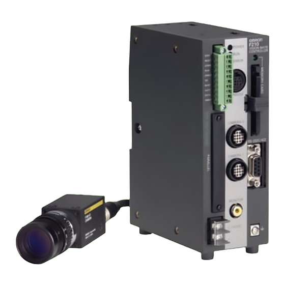
- Page 1 Cat. No. SCHB-738B F210 Vision Sensor SETUP MANUAL...
- Page 2 Terms. Please EXPRESS OR IMPLIED, ABOUT NON-INFRINGEMENT, MERCHANTABIL- contact your Omron representative to confirm any additional terms for sales ITY OR FITNESS FOR A PARTICULAR PURPOSE OF THE GOODS. from your Omron company.
-
Page 3: Introduction
SECTION 5 Troubleshooting and Maintenance INTRODUCTION Thank you for your purchase of this F210-C10/C15 (hereinafter referred to as the Controller). This manual explains how to use the Controller.Please observe the following points when using the Controller. - Please read and understand this manual thoroughly before using the Controller so that it is not used incorrectly. -
Page 4: Table Of Contents
Table of Contents Precautions in using the Product Confirming Package Contents Editor’s Note SECTION 1 Features Vision Sensor F210 Features SECTION 2 Installation and Connections Basic System Configuration Component Names and Functions Mounting the Controller Connecting Peripheral Devices Power Supply and Ground... - Page 5 INTRODUCTION SECTION 5 Troubleshooting and Maintenance Troubleshooting Q&A Maintenance Specifications F300-Series Camera Parameters Connecting a Strobe Device F210 Setup Manual...
-
Page 6: Precautions In Using The Product
PRODUCTS, WHETHER SUCH CLAIM IS BASED ON CONTRACT, WARRANTY, NEGLIGENCE, OR STRICT LIABILITY. In no event shall the responsibility of OMRON for any act exceed the individual price of the product on which liability is asserted. IN NO EVENT SHALL OMRON BE RESPONSIBLE FOR WARRANTY, REPAIR, OR OTHER CLAIMS... - Page 7 INTRODUCTION SUITABILITY FOR USE OMRON shall not be responsible for conformity with any standards, codes, or regulations that apply to the combination of the product in the customer's application or use of the products. At the customer's request, OMRON will provide applicable third party certification documents identifying ratings and limitations of use that apply to the products.
- Page 8 Additionally there may be significant property damage. Meanings of Alert Symbols The following alert symbols are used in this manual. Indicates the possibility of explosion under specific conditions. F210 Setup Manual...
- Page 9 The lithium battery may start a fire, explode, or burn if not treated properly. Regulations and Standards The Controller complies with the EC Directive and EN standard below. 1.EC Directive EMC Directive:No. 89/336/EEC 2.EN Standards (European Standards) EN 61326: 1997/Annex A+A1: 1998 (EMI: Class A)+A2:2001 F210 Setup Manual...
-
Page 10: Installation Environment
• If you suspect an error or malfunction, stop using the Controller immediately, turn OFF the power supply, and consult your OMRON representative. • Do not touch fluorescent or halogen lights while the power is ON or immediately after the power is turned OFF. - Page 11 • Place where it will not come into contact with water, oils or chemicals Orientation of Controller To improve heat dissipation, install the Controller in the following orientation only. Do not install the Controller upside down as shown in the following diagram. F210 Setup Manual...
- Page 12 Control panel Controller Louver Noise resistance • Do not install the Controller in a cabinet containing high-voltage equipment. • Do not install the Controller within 200 mm of power cables. Power lines 200mm min. 200mm min. Controller F210 Setup Manual...
- Page 13 INTRODUCTION Component Installation and Handling OMRON Components Use a Camera, Camera Cable, and Console designed specifically for the Controller. Connecting Cables Always turn OFF the Controller’s power before connecting or disconnecting a camera or cable. Handling the Camera The Camera’s case is connected to the 0V line in the internal circuits. Observe the following precautions to prevent noise interference.
- Page 14 Do not use the RESET input immediately after power is turned ON. When using the RESET input to synchronize startup timing, wait at least 1 second after the Controller’s power supply is turned ON before turning ON the RESET signal. F210 Setup Manual...
-
Page 15: Confirming Package Contents
Confirming Package Contents Check the contents of the package as soon as you receive the Controller. It is extremely rare for components to be missing, but contact the nearest OMRON representative if any of the following items are missing. • Controller…Qty.: 1 •... -
Page 16: Editor's Note
Indicates information helpful in operation, such as the definition of terms. Product Availability Some of the products listed may not be available in some countries. Please contact your nearest OMRON sales office by referring to the addresses provided at the back of this manual. F210 Setup Manual... -
Page 17: Section 1 Features
SECTION 1 Features Vision Sensor F210 Features F210 Setup Manual... -
Page 18: Vision Sensor
The visual inspections can be automated and complicated inspections can be performed accurately at high speeds. The OMRON Vision Sensor helps create production lines with a highly efficient inspection system, which is important to meet current demands for small-lot, variable-product production, produce greater added- value, and improve product quality. -
Page 19: F210 Features
SECTION 1 Features F210 Features Application software (sold separately) is installed in the controller and used. Inspection conditions can be set simply and flexibly using the flow-chart system. First, install the processing items necessary for inspection from the application software. - Page 20 SECTION 1 Features MEMO F210 Setup Manual...
-
Page 21: Section 2 Installation And Connections
SECTION 2 Installation and Connections Basic System Configuration Component Names and Functions Mounting the Controller Connecting Peripheral Devices Wiring the Power Supply F210 Setup Manual... -
Page 22: Basic System Configuration
The following diagram shows the basic system configuration. Some of the components shown in the configuration diagram are special OMRON products that cannot be substituted with comparable devices. Using devices other than OMRON products may result in damage to the system. (“*” indicates a special OMRON product.) - Page 23 F300-series Cameras can also be connected. Up to four Cameras can be connected, but they must all have the same model number. Camera type Camera Cable F300-S F160-VSR4 F300-S2R F160-VSR3 F300-S3DR F300-S4R Details on parameter settings p.75 F210 Setup Manual...
-
Page 24: Component Names And Functions
Memory card indicator Lit when power is being supplied to the corresponding Memory Card. (The Memory Card must not be inserted or removed when this indicator is lit.) Console Connector Connects the Controller to a Console. F210 Setup Manual... -
Page 25: Mounting The Controller
Hook the controller into the DIN track as shown in the diagram and then press in at the bottom until the controller locks into place. Removing the Controller Use a flat-bladed screwdriver to pull the hook down and then pull out the controller from the bottom. F210 Setup Manual... - Page 26 Rear Panel Mounting Attach the bracket to the controller. The bracket and screws (M3 x 6) are supplied with the controller. Have the four M4 screws ready and screw them into the mount positions. Mounting dimensions (Unit: mm) F210 Setup Manual...
- Page 27 SECTION 2 Installation and Connections Side Panel Mounting Mounting dimensions (Unit: mm) 4-M3 (screw engagement length: 4.8 mm or less) F210 Setup Manual...
- Page 28 SECTION 2 Installation and Connections Side Panel Mounting Mounting dimensions (Unit: mm) 4-M4 (screw engagement length: 6 mm or less) F210 Setup Manual...
-
Page 29: Connecting Peripheral Devices
F150-VM Monitor Cable, positioning the ferrite core about 10 mm from the Controller’ side connector. Ferrite core Approx. 10mm The cable must be looped one turn inside the ferrite core. Connecting a Camera Connect the camera cable to the Controller’s Camera connector. F210 Setup Manual... - Page 30 • The camera mounting distance is an approximate value. Mount the Camera so that the distance to the measurement object can be adjusted easily. If the object size and field of vision are incompatible, use a standard CCTV lens and light source. p.32 F210 Setup Manual...
-
Page 31: Power Supply And Ground
Use a grounding point that is as close as possible and keep the ground wire as short as possible. Ground to 100 Ω or less. F210 Setup Manual... -
Page 32: Wiring The Power Supply
Manufacturer Item 1.6A min. 24 VDC +10%, -15% OMRON Corporation S82K-05024 Use a DC power supply with countermeasures against high voltages (safe extra low-voltage circuits on the secondary side). If the system must meet UL standards, use a UL class II power supply. -
Page 33: Section 3 Lenses, Lighting, And Memory Cards
SECTION 3 Lenses, Lighting, and Memory Cards CCTV Lenses Lighting Memory Cards F210 Setup Manual... -
Page 34: Cctv Lenses
Camera vision of 40 mm is needed at the Extension Tube (mm) measurement object, camera Lens distance of 200 mm and 1-mm Camera distance A (mm) Extension Tube are required. Measurement object Field of vision L (mm) F210 Setup Manual... - Page 35 Since these Extension Tubes are placed over the threaded section of the Lens or other Extension Tube, the connection may loosen when more than one 0.5-mm or 1.0-mm Extension Tube are used together. • Reinforcement may be required for combinations of Extension Tubes exceeding 30 mm if the Camera is subject to vibration. F210 Setup Manual...
-
Page 36: Lighting
Camera Camera Light source Half mirror Light source Measurement object Measurement object Applications: Surface inspections, positioning, and Applications: Inspections for surface gloss hole inspections of comparatively small objects F210 Setup Manual... -
Page 37: Memory Cards
Memory Card into the computer and copying the desired data.The following procedures also apply to the Memory Card containing the Application Software. Recommended Model Manufacturer Item Capacity OMRON Corporation F160-N64S(S) 64 MB OMRON Corporation QM300-N128S 128 MB A filler card with no memory is inserted into the Controller’s Memory Card slot before the Controller is shipped.Remove this... - Page 38 II compatible) or CompactFlash™ drive. The Memory Card must be inserted into a PC Card Adapter in order to be used in a PC Card drive. Recommended Model PC Card Adapter Name Manufacturer Item PC Card Adapter OMRON Corporation HMC-AP001 F210 Setup Manual...
-
Page 39: Section 4 Connecting External Devices
SECTION 4 Connecting External Devices Parallel Connection Methods Connecting through the Serial Interface F210 Setup Manual... -
Page 40: Parallel Connection Methods
Use a DC power supply with countermeasures against high voltages (safe extra low-voltage circuits on the secondary side) for the COMIN and COMOUT terminals.If the system must meet UL standards, use a UL class II power supply. F210 Setup Manual... - Page 41 Loosen the wire fixing screw using a flat-bladed screwdriver. Counter-clockwise Insert the wire. Tighten the screw. Clockwise Plug in the connector into the controller. Tighten the fixing screw. The screw must be tightened with a torque of 0.22 to 0.25N·m. F210 Setup Manual...
- Page 42 B17 DO10 Yellow ■■■■ Yellow ■■■■ A18 DO11 B18 DO12 Data output Green ■■■■ Green ■■■■ A19 DO13 Gray B19 DO14 Gray ■■■■ ■■■■ A20 DO15 White B20 COMOUT3 White Common for DO8 to DO15 ■■■■ ■■■■ F210 Setup Manual...
- Page 43 A parallel I/O cable can be assembled using the following connector and cover or equivalent components. Keep the cable length less than 30 m. Manufacturer Item Connector Fujitsu FCN-361J040-AU Cover Fujitsu FCN-360C040-B Double-check the connector wiring for mistakes before turning ON the power supply for the first time. F210 Setup Manual...
- Page 44 SECTION 4 Connecting External Devices I/O Specifications Input Specifications Item Specification Model F210-C10 (NPN mode) F210-C15 (PNP mode) Input voltage 12 to 24 VDC ±10% ON current *1 5 to 15 mA ON voltage *1 8.8 V max. OFF current *2 0.1 mA max.
-
Page 45: Connecting Through The Serial Interface
RS-232C cable Controller Multi-drop Connection (Normal) Communications between one computer and several Controllers (at most 31 Controllers) is possible using Link Adapters. RS-232C cable Link Adapter Recommended Model OMRON Corporation RS-422 3G2A9-AL004-E cable RS-422 cable Recommended Link Adapter Link Adapter... - Page 46 For RS-422 SDB(+) For RS-422 SDA(-) For RS-422 Signal ground A parallel I/O cable can be assembled using the following connector and cover or equivalent components. Recommended Model Manufacturer Item Plug OMRON Corporation XM2A-0901 Hood OMRON Corporation XM2S-0911 F210 Setup Manual...
- Page 47 RDB(+) RDB(+) RDA(-) RDA(-) SDB(+) SDB(+) SDA(-) SDA(-) Use only shielded cable. Pin numbers on the external device will depend on the device being connected. Refer to the manual for the personal computer or PLC being connected. F210 Setup Manual...
- Page 48 Peripheral devices may be damaged if the cable is connected or disconnected with the power ON. The various connectors on the Controller are capped when the Controller is shipped.When a connector is not being used, leave the cover in place or replace the cover to protect against dust, dirt, and static electricity. F210 Setup Manual...
-
Page 49: Section 5 Troubleshooting And Maintenance
SECTION 5 Troubleshooting and Maintenance Troubleshooting Q&A Maintenance Specifications F300-Series Camera Parameters Connecting a Strobe Device F210 Setup Manual... -
Page 50: Troubleshooting
•The Camera Cable is not correctly connected. (when a standard CCTV •The lens iris is opened or closed too far. lens and lighting are used) •The shutter speed is not suitable. p.34 •The lighting method is not suitable. F210 Setup Manual... - Page 51 •The trigger signal has not been input. externally. •The cables are not correctly wired. p.38 •The signal line is disconnected. Operation The status of communications can be checked with the Manual I/O monitor. •The Controller is not in Run mode. F210 Setup Manual...
- Page 52 •The communications mode was not set to Menu in the Operation operations from [System settings/Communication/Serial]. Manual computer. Data cannot be saved. •The Controller’s communications specifications do not match those of the external device. Operation Manual •Is flow control turned OFF under [System settings/Communication/Normal]? F210 Setup Manual...
-
Page 53: Q&A
Can the F150-LT10A Light Yes, it can be connected and the following Lenses are available. be connected to the F160- F160-S2 • Lens with 20-mm field of vision: F150-LE20 Camera? • Lens with 50-mm field of vision: F150-LE50 F210 Setup Manual... - Page 54 Cabling Errors Questions Answers A recommended OMRON One of the following OMRON cables can be used. Select a cable that works with RS-232C cable is not being the device being connected. used. Connecting to a PC/AT or compatible computer (9-pin connector) •...
-
Page 55: Maintenance
Disconnect the light cable from the light connector on the back of the Camera. Remove the light cable from the slot in the camera base. Remove the two screws securing the Light. Remove the Light from the Camera. Do not disassemble the Lens. F210 Setup Manual... - Page 56 Mount the Light on the Camera. Screw in the two screws that secure the Light. Place the light cable in the slot in the camera base. Connect the light cable to the light connector on the back of the Camera. F210 Setup Manual...
- Page 57 When you want to use the Camera alone without connecting an Intelligent Lighting, use M2 × 3 screws in the bottom of the Camera instead of the long screws removed in step 4. The screws removed in step 3 are not needed. F210 Setup Manual...
- Page 58 Screw in the two screws that secure the Light. Screw in the two screws that secure the Light. Place the light cable in the slot in the camera base. Connect the light cable to the light connector on the back of the Camera. F210 Setup Manual...
-
Page 59: Replacing The Battery
The used battery must be disposed of as industrial waste. Manufacturer Item OMRON Corporation 3Z49-BAT1 Always turn OFF the power supply before replacing the battery. The new battery must be installed within two minutes after the old battery is removed, otherwise the clock will be reset. - Page 60 • Turn OFF the power and take safety precautions before conducting inspections. Electrical shock can result from attempting safety inspections with the power turned ON. • Do not use thinners or benzene to clean the Controller. F210 Setup Manual...
-
Page 61: Specifications
SECTION 5 Troubleshooting and Maintenance Specifications Controller F210-C10/C15 (Unit: mm) Four M3 taps, Four M3 taps, Depth 4.8 Depth 4.8 115 min. Four M3 taps, Depth 6 Specification Model F210-C10 F210-C15 Input/Output type Power supply voltage 20.4 to 26.4 VDC Current consumption Approx. - Page 62 SECTION 5 Troubleshooting and Maintenance Camera with Light F150-SL20A/SL50A (Unit:mm) F150-LT10A Light Two M4 taps, Depth 8 1/4-20UNC tap, Depth 8 Camera with Intelligent Lighting F150-SLC20 F150-LT20 Light (Unit:mm) Two M4 taps, Depth 10 1/4-20UNC tap, Depth 10 F210 Setup Manual...
- Page 63 F150-SLC50 (Unit:mm) F150-LTC50 Light Two M4 taps, Depth 10 1/4-20UNC tap, Depth 10 Camera Only F150-S1A (Unit:mm) Light Connector (8.8 dia.) Camera cable connector C mount (11.8 dia.) Two M4 taps, Depth 8 1/4-20UNC tap, Depth 8 F210 Setup Manual...
- Page 64 SECTION 5 Troubleshooting and Maintenance Camera with Intelligent Lighting F160-SLC20 (Unit:mm) F150-LT20 Light 1/4-20UNC tap, Depth 10 Two M4 taps, Depth 10 F210 Setup Manual...
- Page 65 F160-SLC50 (Unit:mm) F150-LTC50 Light 1/4-20UNC tap, Depth 10 Two M4 taps, Depth 10 Camera Only F160-S1/F160-S2 (Unit:mm) Light Connector (8.8 dia.) Camera cable C mount connector (11.8 dia.) Two M4 taps, Depth 8 1/4-20UNC tap, Depth 8 F210 Setup Manual...
- Page 66 Depends on lens being used. distance 71mm 76mm 25mm 26.5mm 25mm 26.5mm Field of vision 20 mm 50mm 20 mm 50mm 20 mm 50mm × × × × × × 20 mm 50mm 20 mm 50mm 20 mm 50mm F210 Setup Manual...
- Page 67 Operating and storage: 35% to 85% (with no condensation) Ambient environment No corrosive gases Degree of protection IEC60529 IP20 (in-panel) Minimum bending radius 75mm Materials Body: ABS Cable sheathing: Heat-resistant PVC Connector: PC and PBT Weight Approx. 135 g F210 Setup Manual...
- Page 68 Cable sheathing: Heat-resistant PVC Connector: PC and PBT Weight Approx. 160g The switch on the back of the F160-KP must be set to “ENABLE”. These keys will be disabled if the switch is set to “DISABLE”. ENABLE F210 Setup Manual...
- Page 69 Camera Connector Signal Signal Power Power VIDEO GND VIDEO VIDEO GND ESCNT1 VIDEO (Open) ESCNT1 SCAN ESCNT2 ESCNT2 INDEX INDEX SCAN Shell – – Shell Connector model Connector model Hirose HR10A-10P-12S Hirose PR17A-13P-12PC (equivalent part) (equivalent part) F210 Setup Manual...
- Page 70 Camera Connector Signal Signal Power Power VIDEO GND VIDEO GND VIDEO HD GND ESCNT1 VIDEO SCAN – ESCNT2 INDEX(SI) INDEX VD GND Shell – – Shell Connector model Connector model Hirose HR10A-10P-12S Hirose PR17A-13P-12PC (equivalent part) (equivalent part) F210 Setup Manual...
- Page 71 Signal Signal Power Power VIDEO GND VIDEO GND VIDEO HD GND ESCNT1 VIDEO SCAN – ESCNT2 INDEX(SI) INDEX Power VD GND Shell – – Shell Connector model Connector model Hirose HR10A-10P-12S Hirose PR17A-13P-12PC (equivalent part) (equivalent part) F210 Setup Manual...
- Page 72 Storage: -25 to 65°C (with no condensation) Ambient humidity Operating and storage: 35% to 85% (with no condensation) Ambient environment No corrosive gases Materials Cable sheathing: Super flame retardant PVC Connector: PVC Minimum bending radius 50mm Weight Approx. 40g Accessories BNC Jack Adapter F210 Setup Manual...
- Page 73 Storage: -25 to 65°C (with no condensation) Ambient humidity Operating and storage: 35% to 85% (with no condensation) Ambient environment No corrosive gases Materials Cable sheathing: Heat-resistant PVC Connector: Polyesterresin Minimum bending radius 120mm Weight Approx. 340g F210 Setup Manual...
- Page 74 85:1 (typical) Viewable angle 25° up/down and 50° left/right (with a contrast ratio > 10) Luminance 250 cd/m (typical) Backlight Cold cathode fluorescent light Response speed 60 ms max. Input signal NTSC composite video (1.0 V/75 Ω termination) F210 Setup Manual...
- Page 75 75 Ω, high impedance (selectable) I/O impedance I/O level and polarity Composite image signal:1 V (peak to peak) Image: 0.7 V (peak to peak), positive Synchronization: 0.3 V (peak to peak), negative NTSC composite video (1.0 V/75 Ω termination) Input signal F210 Setup Manual...
- Page 76 Operating: 0 to 60°C (with no condensation) Storage: -25 to 85°C (with no condensation) Ambient humidity Operating and storage: 8% to 95% (with no condensation) Ambient environment No corrosive gases Life expectancy 300,000 overwrite operations Number of pins 50 pins Weight Approx. 15g F210 Setup Manual...
-
Page 77: F300-Series Camera Parameters
1/10000 1/30000 1/50000 *1: The shutter speed is set in the Camera itself. *2: Set the shutter trigger pulse width to match the strobe’s specifications only when a strobe is being used. –: These settings are ignored. F210 Setup Manual... -
Page 78: Connecting A Strobe Device
(1H = 63 µs) Negative Note: Depending upon the timing, W may have an error of up to 1H. Combining an OMRON Camera and Strobe The following table shows the timing polarity. Use a strobe that is compatible with this timing. Camera... - Page 79 MEMO F210 Setup Manual...
-
Page 80: Revision History
Revision History A manual revision code appears as a suffix to the catalog number on the front cover of the manual. Cat. No. SCHB-738B revision code Revision Date Revised content 03 January Orginal Production of English Version F210 Setup Manual... - Page 81 For US technical support or other inquiries: 800.556.6766 OMRON CANADA, INC. Milner Avenue Toronto, Ontario M 416.286.6465 OMRON ON-LINE Global - http://www.omron.com USA - http://www.omron.com/oei Canada - http://www.omron.ca SCHB-738B 2/04 ©2004 OMRON ELECTRONICS LLC Specifications subject to change without notice. Printed in the U.S.A.