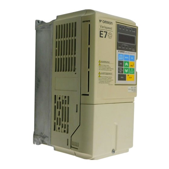
Omron VARISPEED E7 User Manual
Variable torque frequency inverter
Hide thumbs
Also See for VARISPEED E7:
- Manual (13 pages) ,
- Datasheet (20 pages) ,
- User manual (291 pages)
Table of Contents
Troubleshooting

Related Manuals for Omron VARISPEED E7


Summary of Contents for Omron VARISPEED E7
- Page 1 Manual No. TOE-S616-56.1-03-OY VARISPEED E7 Variable Torque Frequency Inverter USER’S MANUAL...
-
Page 2: Table Of Contents
Keeping the IP54 protection ..................1-14 Installation Orientation and Space .............1-15 Accessing the Inverter Terminals ..............1-16 Removing the Terminal Cover (IP00 and NEMA 1 / IP20 Inverters) ......1-16 Attaching the Terminal Cover ..................1-16 Opening the Door (IP54 Inverters) ................1-17 Closing the Door (IP54 Inverters) ................ - Page 3 Checks ........................2-37 Installing and Wiring Option Cards ............2-38 Option Card Models ....................2-38 Installation in IP00 and NEMA 1 / IP20 Inverters ............2-38 Installation in IP54 Inverters ..................2-39 Digital Operator and Modes............3-1 Digital Operator ................... 3-2 Digital Operator Display ....................
- Page 4 Digital Operator Parameters: o ..................5-36 Motor Autotuning: T ..................... 5-40 Monitor Parameters: U ....................5-41 Setting Values that Change with the V/f Pattern Selection (E1-03) ......5-46 Factory Settings that Change with the Inverter Capacity (o2-04) ........ 5-47 Parameter Settings by Function..........6-1 Carrier Frequency Selection ................6-2...
- Page 5 Automatic Restart ..................6-38 Restarting Automatically After Momentary Power Loss ..........6-38 Speed Search ......................6-39 Continuing Operation at Constant Speed When Frequency Reference Is Lost ..6-44 Restarting Operation After Transient Fault (Auto Restart Function) ......6-45 Inverter Protection ..................6-47 Inverter Overheat Protection ..................
- Page 6 If the Motor Does Not Operate ..................7-16 If the Direction of the Motor Rotation is Reversed ............7-17 If the Motor Does Not Put Out Torque or If Acceleration is Slow ......... 7-17 If the Motor Operates at Higher Speed than the Frequency Reference ...... 7-17 If Motor Deceleration is Slow ..................
-
Page 8: Warnings
Cables must not be connected or disconnected, nor signal tests carried out, while the power is switched on. The Varispeed E7 DC bus capacitor remains charged even after the power has been switched off. To avoid an electric shock hazard, disconnect the frequency inverter from the mains before carrying out maintenance. -
Page 9: Safety Precautions And Instructions For Use
The DC bus capacitors can remain live for about 5 minutes after the inverter is disconnected from the power. It is therefore necessary to wait for this time before opening its covers. All of the main circuit terminals may still carry dangerous voltages. - Page 10 (EMC), e.g. shielding, grounding, filter arrangement and laying of cables. This also applies to equipment with the CE mark. It is the responsibility of the manufacturer of the system or machine to ensure conformity with EMC limits.
-
Page 11: Emc Compatibility
Use a power cable with well-grounded shield. For motor cables up to 50 meters in length use shielded cables. Arrange all grounds so as to maximize the area of the end of the lead in contact with the ground terminal (e.g. - Page 12 Ground clip Ground plate The grounding surfaces must be highly conductive bare metal. Remove any coats of varnish and paint. – Ground the cable shields at both ends. – Ground the motor of the machine. Further informations can be found in the document EZZ006543 which can be ordered at Omron Yaskawa...
-
Page 13: Line Filters
Line Filters The IP54 version is already equipped with a internal EMC filter. For the IP00 and NEMA 1 / IP20 versions of the Varispeed E7 the recommended line filters are as follows: Recommended Line Filters for Varispeed E7 (IP00 and NEMA 1 / IP20) - Page 14 Class A, 100 ambient temperature: 45°C max EMC Specifications of Varispeed E7 (IP54) The Varispeed E7 IP54 is already equipped with an internal EMC filter. The Varispeed E7 IP54 complies with EN55011 class A with a motor cable length up to 25m.
- Page 15 Installation inverters and EMC filters L1 L3 Ground Bonds ( remove any paint ) Line Inverter Filter Load Cable Length as short as possible Metal Plate Motor cable screened Ground Bonds ( remove any paint )
-
Page 16: Registered Trademarks
Registered Trademarks The following registered trademarks are used in this manual. • DeviceNet is a registered trademark of the ODVA (Open DeviceNet Vendors Association, Inc.). InterBus is a registered trademark of Phoenix Contact Co. • • ControlNet is a registered trademark of ControlNet International, Ltd. -
Page 18: Handling Inverters
Handling Inverters This chapter describes the checks required upon receiving or installing an Inverter. Varispeed E7 Introduction..........1-2 Confirmations upon Delivery..........1-4 Exterior and Mounting Dimensions ........1-9 Checking and Controlling the Installation Site ....1-13 Installation Orientation and Space ........1-15 Accessing the Inverter Terminals........1-16... -
Page 19: Varispeed E7 Introduction
200 V and 400 V. The maximum motor capacities The Varispeed E7 Series includes Inverters in two voltage class vary from 0.55 to 300 kW. The inverter is available in protection classes IP00, IP20 and IP54 according to the following table: Table 1.1 Varispeed E7 Models... - Page 20 Varispeed E7 Introduction Specifications Maximum Varispeed E7 (Always specify through the protective structure when ordering.) Motor Voltage Class Capacity Output IEC IP00 NEMA 1 (IEC IP20) IEC IP54 Basic Model Number Capacity kVA CIMR-E7Z CIMR-E7Z CIMR-E7Z 0.55 CIMR-E7Z40P4 40P41 0.75...
-
Page 21: Confirmations Upon Delivery
Door Key Blind Plug (Control Cable Entry) Blind Plug (Fieldbus Cable Entry) If any irregularities in the above items are found, contact the agency from which the Inverter was purchased or your Omron Yaskawa Motion Control representative immediately. Nameplate Information There is a nameplate attached to the side of each Inverter. -
Page 22: Inverter Software Version
Fig 1.3 Inverter Specifications Inverter Software Version The Inverter software version can be read out from the monitor parameter U1-14. The parameter shows the last four digits of the software number (e.g. display is “3021” for the software version VSE103021). -
Page 23: Component Names
Bottom protective cover Fig 1.4 NEMA 1 Inverter Appearance (18.5 kW or Less) The top cover is a protection against foreign bodies (screws, metal scrap from drilling etc.), which could fall into the inverter during the installation in the cabinet. - Page 24 Confirmations upon Delivery Inverters of 22 kW or More The external appearance and component names of the Inverter are shown in 1.6, the terminal arrangement Fig 1.7 Mounting holes Inverter cover Cooling fan Front cover Digital Operator Nameplate Terminal cover Fig 1.6 Inverter Appearance (22 kW or More)
- Page 25 Protection Class IP54 The external appearance and component names of the Inverter are shown in 1.8. Inverter enclosure Digital Operator Door Locks Nameplate Mounting Holes Door Cable Entry Plate Fig 1.8 IP54 Inverter Appearance...
-
Page 26: Exterior And Mounting Dimensions
Max.10 Max.10 200 V Class Inverters of 22 or 110 kW 200 V/400 V Class Inverters of 0.55 to 18.5 kW 400 V Class Inverters of 22 to 160 kW Ø 400 V Class Inverters of 185 to 300 kW... -
Page 27: Nema 1 / Ip20 Inverters
Max.10 Max.10 Grommet 200 V/400 V Class Inverters of 0.55 to 18.5 kW 200 V Class Inverters of 22 to 75 kW 400 V Class Inverters of 22 to 160 kW Fig 1.10 Exterior Diagrams of NEMA 1 / IP20 Inverters... - Page 28 Exterior and Mounting Dimensions Table 1.4 Inverter Dimensions (mm) and Masses (kg) from 0.4 to 160 kW, IP00 and NEMA 1 / IP20 Caloric Value Dimensions (mm) Max. Appli- Cool- Protection Class IP00 Protection Class NEMA 1 / IP20 Total...
- Page 29 Table 1.6 Inverter Dimensions (mm) and Masses (kg) of 400V class inverters 7.5 to 55 kW, IP54 Dimensions (mm) Max. Applica- Voltage Total Cooling ble Motor Mount- Class Approx. Heat Method Output Mass Genera- [kW] Holes d tion ∅ 10 18.5...
-
Page 30: Checking And Controlling The Installation Site
Protection covers are attached to the top and bottom of the NEMA 1 and IP00 Inverters. Be sure to remove the top cover before operating a 200 or 400 V Class Inverter with an output of 18.5 kW or less inside a panel. -
Page 31: Additional Installation Precautions For The Ip54 Inverters
• Inverter, do not carry it holding the door or the cable glands. If the door locks are open or the Inverter is held by the door (or cable glands) when carrying the main body of the Inverter may fall, possibly resulting injury. -
Page 32: Installation Orientation And Space
1. The same space is required horizontally and vertically for Inverters of all protection classes, either IP00, NEMA 1 / IP20 and IP54 Inverters. 2. Always remove the top cover after installing a 200 or 400 V Class Inverter with an output of 18.5 kW or less in a panel. -
Page 33: Accessing The Inverter Terminals
Inverters of 22 kW or More Loosen the screws on the left and right at the top of the terminal cover, pull out the terminal cover in the direc- tion of arrow 1 and then lift up on the terminal in the direction of arrow 2. -
Page 34: Opening The Door (Ip54 Inverters)
Accessing the Inverter Terminals Opening the Door (IP54 Inverters) Unlock the door locks with the provided key by pushing and rotating it 90 degrees in the directions of arrow 1 and open the door in the direction of arrow 2. -
Page 35: Removing/Attaching The Digital Operator And
Removing the Digital Operator Press the lever on the side of the Digital Operator in the direction of arrow 1 to unlock the Digital Operator and lift the Digital Operator in the direction of arrow 2 to remove the Digital Operator as shown in the follow- ing illustration. - Page 36 Removing the Front Cover Press the left and right sides of the front cover in the directions of arrows 1 and lift the bottom of the cover in the direction of arrow 2 to remove the front cover as shown in the following illustration.
-
Page 37: Inverters Of 22 Kw Or More
Digital Operator is mounted to it. 2. Insert the tab on the top of the front cover into the slot on the Inverter and press in on the cover until it clicks into place on the Inverter. -
Page 38: Wiring
Wiring This chapter describes wiring terminals, main circuit terminal connections, main circuit terminal wiring specifications, control circuit terminals, and control circuit wiring specifications. Connection Diagrams ............2-2 Terminal Block Configuration..........2-5 Wiring Main Circuit Terminals ..........2-7 Wiring Control Circuit Terminals ........2-27 Wiring Check..............2-37... -
Page 39: Connection Diagrams
Connection Diagrams The connection diagrams of the Inverters are shown in Fig 2.1 Fig 2.2 When using the Digital Operator, the motor can be operated by wiring only the main circuits. DC reactor to improve input power factor (optional) Short-circuit bar... - Page 40 4 to 20 mA (250 [Default: Output power, 0 to 10 V] Analog input power supply -15 V, 20 mA Input Option Cards Terminating resistance MEMOBUS communication RS-485/422 Twisted-pair Shielded wires shielded wires Fig 2.2 Connection Diagram of IP54 Inverters (Model CIMR-E7Z47P52 Shown Above)
-
Page 41: Circuit Descriptions
H3-13. The default setting is terminal A2. 6. DC reactors to improve the input power factor are built into 200 V Class Inverters from 22 up to 110 kW and 400 V Class Inverters from 22 up to 300 kW. A DC reactor is an option only for Inverters of 18.5 kW or less. Remove... -
Page 42: Terminal Block Configuration
Ground Terminal Fig 2.3 Terminal Arrangement (200V / 400V Class Inverter of 0.4 kW) E(G) E(G) Control Circuit Terminals Carge Indicator Main Circuit Terminals Ground Terminals Fig 2.4 Terminal Arrangement (200V / 400V Class Inverter of 22 kW or more) - Page 43 Refer to manual for connections. M5:2.5N.m M6:4.0-5.0N.m Use 75°C Cu wires or equivalent. NPJU 30012 -1-1 Input Terminals Ground Terminals Fig 2.5 Terminal Arrangement (IP54 Inverter of 18.5kW) Control Terminals Shielding Clamp for Control Cables R/L1 S/L2 S/L3 Input Terminals Output Terminals...
-
Page 44: Wiring Main Circuit Terminals
Wiring Main Circuit Terminals Wiring Main Circuit Terminals Applicable Wire Sizes and Crimp Terminals Select the appropriate wires and crimp terminals from the following tables. Table 2.1 200 V Class Wire Sizes Recom- Possible Inverter Termi- Tightening mended Wire Sizes... - Page 45 150 × 2P 31.4 to 39.2 (300 × 2P) (300) 0.5 to 4 r/l1, Δ/l2 1.3 to 1.4 (20 to 10) (16) The wire thickness is set for copper wires at 75°C.The wire thickness is set for copper wires at 75°...
- Page 46 Wiring Main Circuit Terminals Table 2.2 400 V Class Wire Sizes, NEMA 1/ IP20 and IP00 Inverters Recom- Possible Inverter Termi- Tightening mended Wire Sizes Model Terminal Symbol Torque Wire Type Wire Size CIMR- Screws (N•m) (AWG) (AWG) R/L1, S/L2, T/L3, 2, B1, B2, 1.5 to 4...
- Page 47 Table 2.2 400 V Class Wire Sizes, NEMA 1/ IP20 and IP00 Inverters Recom- Possible Inverter Termi- Tightening mended Wire Sizes Model Terminal Symbol Torque Wire Type Wire Size CIMR- Screws (N•m) (AWG) (AWG) 25 to 50 R/L1, S/L2, T/L3, 1, U/T1, V/T2, W/ 9.0 to 10.0...
- Page 48 Wiring Main Circuit Terminals Table 2.2 400 V Class Wire Sizes, NEMA 1/ IP20 and IP00 Inverters Recom- Possible Inverter Termi- Tightening mended Wire Sizes Model Terminal Symbol Torque Wire Type Wire Size CIMR- Screws (N•m) (AWG) (AWG) 95 × 2P...
- Page 49 Table 2.4 Recommended Wire Types for IP54 Inverters INPUT 4-core Power Cable OUTPUT 4-core shielded Power Cable (-), (+1) e.g. 600V Vinyl Power Cable *1. 4-core power cables or 4-core shielded power cables are available e.g. Lappkabel (Ölflex) or Pirelli 2-12...
- Page 50 18.0 15.0 20.0 Determine the wire size for the main circuit so that line voltage drop is within 2% of the rated voltage. Line voltage drop is calculated as follows: Line voltage drop (V) = x wire resistance (W/km) x wire length (m) x current (A) x 10...
- Page 51 Recommended Crimp Terminals Table 2.6 Recommended Crimp Terminals Recommended Crimp Terminals Wire Cross Section Klaukey Terminal Screws (mm²) 0.5-1.0 620/4 1620/4 GS4-1 630/4 1620/4 GS4-1 630/4 1630/4 GS4-2.5 650/4 1650/4 GS4-6 650/4 1650/4 GS4-6 101 R/5 1650/5 GS5-6 101 R/6...
-
Page 52: Main Circuit Terminal Functions
Wiring Main Circuit Terminals Main Circuit Terminal Functions Main circuit terminal functions are summarized according to terminal symbols in Table 2.7. Wire the termi- nals correctly for the desired purposes. Table 2.7 Main Circuit Terminal Functions Model: CIMR-E7Z Purpose Terminal Symbol... -
Page 53: Main Circuit Configurations
T/L3 V/T2 T/L3 V/T2 R1/L11 R1/L11 W/T3 W/T3 S1/L21 S1/L21 T1/L31 T1/L31 400/200 s 200/l s 200/l Power Control Power Control s 400/l Supply Circuit Supply Circuit Note: Consult your Omron Yaskawa Motion Control representative before using 12-phase rectification. 2-16... - Page 54 Wiring Main Circuit Terminals Table 2.9 Main Circuit Configurations (IP54 Inverters) 400 V class CIMR-E7Z47P52 to 40182 R/L1 U/T1 S/L2 V/T2 filter T/L3 W/T3 Power Control circuits supply CIMR-E7Z40222 to 40552 R/L1 U/T1 S/L2 V/T2 Filter T/L3 W/T3 Power Control...
-
Page 55: Standard Connection Diagrams
/ l1 r / l1 200 / l / l2 400 / l Control power is supplied internally from the DC bus at all inverter models. Fig 2.7 Main Circuit Terminal Connections for NEMA 1 / IP20 Inverters 2-18... - Page 56 Resistor (optional) CDBR Braking Unit (optional) DC reactor (optional) U/T1 R/L1 V/T2 S/L2 W/T3 T/L3 3 Phase 400VAC Be sure to remove the short-circuit bar before connecting the DC reac- tor. Fig 2.8 Main Circuit Terminal Connections for IP54 Inverters 2-19...
-
Page 57: Wiring The Main Circuits
Wiring Main Circuit Inputs Observe the following precautions for the main circuit power supply input. Installing Fuses To protect the inverter, it is recommended to use semiconductor fuses like they are shown in the table below. Table 2.10 Input Fuses Rated Inverter... - Page 58 Inverter and with an operating time of 0.1 s or more. Installing a Magnetic Contactor If the power supply for the main circuit is to be shut off by a control circuit, a magnetic contactor can be used. The following things should be considered: The Inverter can be started and stopped by opening and closing the magnetic contactor on the primary side.
- Page 59 Never Short or Ground Output Terminals If the output terminals are touched with bare hands or the output wires come into contact with the Inverter cas- ing, an electric shock or grounding may occur. This is extremely hazardous. Do not short the output wires.
- Page 60 Ground Wiring Observe the following precautions when wiring the ground line. Always use the ground terminal of the 200 V Inverter with a ground resistance of less than 100 Ω and that • of the 400 V Inverter with a ground resistance of less than 10 Ω.
- Page 61 When connecting two or more Braking Units in parallel, use the wiring and jumper settings like shown in 2.11. There is a jumper for selecting whether each Braking Unit is to be a master or slave. Select “Master” for the first Braking Unit only, and select “Slave” for all other Braking Units (i.e., from the second Unit onwards).
- Page 62 Note: To ensure conformity to EMC regulations the shielded cable has to be locked tightly by the metal cable gland. Confirm the cable length and the terminal specifications before fitting the metal cable gland.
- Page 63 Install the shielded output cable as shown in the 2.12. Remove the braided shield on the output cable entirely from the entry hole to the terminal end to avoid short circuit to the input terminals or the filter. Remove the braided shield entirely from the entry hole to the terminal end.
-
Page 64: Wiring Control Circuit Terminals
For remote operation using analog signals, keep the control line length between the Analog Operator or oper- ation signals and the Inverter to 50 m or less, and separate the lines from main power lines or other control cir- cuits to reduce induction from peripheral devices. - Page 65 Cable-End Sleeves for Signal Lines Models and sizes of straight solderless terminals are shown in the following table. Table 2.13 Straight Solderless Terminal Sizes Model Manufacturer Wire Size mm (AWG) 0.25 (24) AI 0.25 - 8YE 12.5 0.5 (20) AI 0.5 - 8WH 0.75 (18)
- Page 66 Wiring Control Circuit Terminals Earthing the Control Cable Shield in IP54 Inverters For a appropriate shielding earth clamps have been mounted in the IP54 inverters. Fig 2.16 Fig 2.17 show where the earth clamps can be found. Control Terminal Cable Mounting Base Earth Clamp Fig 2.16 Earth Clamp of IP54 Inverters with 7.5 to 18.5kW capacity...
- Page 67 Use the following procedure to clamp and shield the control cables in the IP54 Inverters. Loosen both mounting screws for the earth clamp Insert the shielded cable for control between earth clamp and cable mounting base Tighten the screws alternately until screws are fixed to the end.
-
Page 68: Control Circuit Terminal Functions
Wiring Control Circuit Terminals Control Circuit Terminal Functions The functions of the control circuit terminals are shown in Table 2.14. Table 2.14 Control Circuit Terminals with Default Settings Type Signal Name Function Signal Level Forward run/stop command Forward run when ON; stopped when OFF. - Page 69 – – *1. The default settings are given for terminals S3 to S7. For a 3-wire sequence, the default settings are a 3-wire sequence for S5, multi-step speed setting 1 for S6 and multi-step speed setting 2 for S7. *2. Do not use this power supply for supplying any external equipment.
- Page 70 The input terminal logic can be switched between sinking mode (0-V common, NPN) and sourcing mode (+24V common, PNP) by using the terminals SN, SC, and SP. An external power supply is also supported, providing more freedom in signal input methods.
- Page 71 Table 2.15 Sinking / Sourcing Mode and Input Signals Internal Power Source - Sourcing Mode (PNP) External Power Source - Sourcing Mode (PNP) External +24V 2-34...
-
Page 72: Control Circuit Terminal Connections
Wiring Control Circuit Terminals Control Circuit Terminal Connections Connections to Inverter control circuit terminals are shown in 2.21. Varispeed E7 CIMR-E7Z47P5 ≈ ≈ Forward Run/Stop Fault contact output 250 VAC, 1 A max. Reverse Run/Stop 30 VDC, 1 A max. -
Page 73: Control Circuit Wiring Precautions
Separate wiring for control circuit terminals MA, MB, MC, M1, M2, M3, and M4 (relay outputs) from wiring to other control circuit terminals. • If using an optional external power supply, it shall be a UL Listed Class 2 power supply source. Use twisted-pair or shielded twisted-pair cables for control circuits to prevent operating faults. •... -
Page 74: Wiring Check
This will keep IP54 protection for the inverter. Otherwise the equipment may be damaged by the ingress of water or dust. WARNING • Be sure to ground the grounding terminal. Moreover be sure to ground the shield of motor cable on the motor side. Otherwise an electric shock can occur. 2-37... -
Page 75: Installing And Wiring Option Cards
Preventing Option Card Connectors from Rising After installing the Option Card insert the Option Clip to prevent the side with the connector from rising. The Option Clip can be easily removed before installing the card by holding onto the protruding portion of the Clip and pulling it out. -
Page 76: Installation In Ip54 Inverters
Before mounting an Option Card, open the inverter door and be sure that the charge indicator inside the Inverter does not glow anymore. After that remove the option clip and mount the Option Card like with the IP00 or NEMA 1 Inverter. - Page 77 2-40...
-
Page 78: Digital Operator And Modes
Digital Operator and Modes This chapter describes Digital Operator displays and functions, and provides an overview of operating modes and switching between modes. Digital Operator..............3-2 Modes ................3-5... -
Page 79: Digital Operator
This section describes the displays and functions of the Digital Operator. Digital Operator Display The key names and functions of the Digital Operator for the IP00 and NEMA 1 / IP20 inverters are described below. This operator is referred to as “LED Digital Operator” or JVOP-161-OY... -
Page 80: Digital Operator Keys
Digital Operator The IP54 Inverter is equipped with a different type of digital operator, the LCD Digital Operator or JVOP- 160-OY. This Operator features a clear text display with 5 lines while the key names and functions are the same, see 3.2. - Page 81 The RUN key indicator will flash and the STOP key indicator will light while a DC current is injected in the motor. The relationship between the indicators on the RUN and STOP keys and the Inverter status is shown in 3.3.
-
Page 82: Modes
This section describes the Inverter's modes and switching between modes. Inverter Modes The Inverter's user parameters and monitoring functions are organized in groups called modes that make it easier to read and set user parameters. The Inverter is equipped with 5 modes. -
Page 83: Switching Modes
Switching Modes The mode selection display will appear when the MENU key is pressed from any other operator display. Press the MENU key to switch between the different modes. When the DATA/ENTER key is pressed the monitor display is entered. Depending on the entered menu the monitor data or parameters are displayed. - Page 84 Modes Example Operations with LCD Digital Operator Fig 3.5 shows the mode transition appearance with the LCD digital operator. Display at Startup -DRIVE- Frequency Ref U1- 01=60.00Hz U1-02= 60.00Hz U1-03= 10.05A Mode Selection MENU Monitor Display Setting Display Display -DRIVE-...
-
Page 85: Drive Mode
When b1-01 (Reference selection is set to 0, the frequency reference can be changed from the frequency set- ting display. Use the Increment, Decrement and Shift/RESET keys to change it. The set value will be accepted when the DATA/ENTER key has been pressed. -
Page 86: Quick Programming Mode
Fig 3.7 Operations in Drive Mode with LCD Digital Operator To run the Inverter after viewing/changing parameters press the MENU key and the DATA/ENTER key in sequence to enter the Drive mode. A Run command is not accepted as long as the Inverter in any other display. - Page 87 Example Operations with LED Digital Operator Fig 3.8 shows example operations in Quick Programming Mode with the LED Digital Operator. Mode Selection Display Monitor Display MENU Quick Programming Mode Reference Source RUN Command Source Motor Rated Current Fig 3.8 Operations in Quick Programming Mode with LED Digital Operators Example Operations with LCD Operator Fig 3.9...
-
Page 88: Advanced Programming Mode
The parameters can be changed from the setting display. Use the Increment, Decrement, and Shift/RESET keys to change the settings. The setting will be saved and the display will return to the monitor display when the DATA/Enter key is pressed. - Page 89 Example Operations with LCD Digital Operator Fig 3.11 shows example operations in Advanced Programming Mode using the LCD Digital Operator. Mode Selection Display Monitor Display Setting Display -ADV- -ADV- -ADV- -ADV- Initialization Select Language RESET Select Language ** Main Menu **...
- Page 90 Setting User Parameters using the LED Digital Operator Below in Table 3.3 the procedure to change C1-01 (Acceleration Time 1) from 10 sec. to 20 sec. is shown using the LED Digital Operator Table 3.3 Setting User Parameters in Advanced Programming Mode using the LED Digital Operator...
- Page 91 Setting User Parameters using the LCD Digital Operator Below in Table 3.4 the procedure to change C1-01 (Acceleration Time 1) from 10 sec. to 20 sec. is shown using the LCD Digital Operator. Table 3.4 Setting User Parameters in Advanced Programming Mode using the LCD Digital Operator...
-
Page 92: Verify Mode
Modes Verify Mode Verify mode is used to display any parameters that have been changed from their default settings, either by programming or autotuning. If no parameter setting has been changed the display will show “NONE” with the LED operator or “None Modified” with the LCD operator. - Page 93 Example Operations with LCD Digital Operator Fig 3.13 shows an example of operations in the Verify Mode using the LCD Digital Operator. The same parameters have been modified like in Fig 3.12 Mode Selection Display Monitor Display Setting Display MENU...
-
Page 94: Autotuning Mode
Example Operations with LED Digital Operator Set the motor rated output power (in kW) and the motor rated current, specified on the motor nameplate and then press the RUN key. The motor is automatically run and the line-to-line resistance is measured. - Page 95 Example Operations with LCD Digital Operator Fig 3.15 shows an example for an Autotuning procedure with LCD Digital Operator Autotuning Mode Selection Display Setting Display Monitor Display -A.TUNE- -A. TUNE- -A. TUNE- Mtr Rated Power ** Main Menu ** Mtr Rated Power - 02= 0.40...
-
Page 96: Trial Operation
Trial Operation This chapter describes the procedures for trial operation of the Inverter and provides an example of trial operation. Trial Operation Procedure..........4-2 Trial Operation ..............4-3 Adjustment Suggestions ..........4-11... -
Page 97: Trial Operation Procedure
Trial Operation Procedure Perform trial operation according to the following flowchart. START Installation Wiring Set power supply voltage jumper. Turn ON power. *1: Set the jumper for 400V class Inverters of 75kW and more Confirm status. Basic settings (Quick programming mode) Set E1-03. -
Page 98: Trial Operation
(400 V Class Inverters of 75 kW or Higher) The power supply voltage jumper must be set for 400 V Class Inverters of 75 kW or higher. Insert the jumper into the voltage connector nearest to the actual power supply voltage. -
Page 99: Checking The Display Status
The frequency reference monitor is dis- Display for normal operation played in the data display section. When a fault has occurred, the details of the fault will be displayed instead of the above display. In that case, refer to Chapter 7, Troubleshooting. -
Page 100: Basic Settings
Trial Operation Basic Settings Before starting the Inverter ensure that it is initialized, i.e. all parameters are set to their factory defaults. Therefor set parameter A1-03 to 2220 for 2-wire initialization or to 3330 for 3-wire initialization. Refer to page 6-9, Run Command for details about 2-wire and 3-wire initialization. - Page 101 *1. Values for 200 V class Inverters are shown. For a 400 V class Inverter the values have to be doubled. *2. The setting range is 10% to 200% of the Inverter rated output current. The value for a 200 V class Inverter of 0.4 kW is given.
-
Page 102: Selecting The V/F Pattern
Trial Operation Selecting the V/f pattern Set either one of the fixed patterns (0 to E) in E1-03 (V/f Pattern Selection) or set F in E1-03 to specify a • user-set pattern as required for the motor and load characteristics in E1-04 to E1-13 in advanced program- ming mode. - Page 103 Digital Operator Displays during Autotuning using LED Digital Operator The following displays will appear on the LED Digital Operator during autotuning. Table 4.2 LED Digital Operator Displays during Autotuning Digital Operator Display Description Motor rated power and current: T1-02 and T1-04 When the Autotuning Mode is entered parameters T1- 02 and T1-04 have to entered.
-
Page 104: Application Settings
• • To use a 0 to 10 V analog signal for a 50 Hz motor for variable-speed operation between 0 and 45 Hz (0% to 90% speed), set H3-02 to 90.0%. To limit the speed range between 20% and 80% set d2-01 to 80.0% and set d2-02 to 20.0%. -
Page 105: Check And Recording User Parameters
Recording User Parameters (o2-03) If o2-03 is set to 1 after completing trial operation, the settings of user parameters will be saved in a separate memory area in the inverter. When the Inverter settings have been changed for any reason, the user parameters can be initialized to the settings saved in the separate memory area by setting A1-03 (Initialize) to 1110. -
Page 106: Adjustment Suggestions
(E1-10) *1. The setting is given for 200 V Class Inverters. Double the voltage for 400 V Class Inverters. The following user parameters will also affect the control system indirectly. Table 4.5 Parameters influencing performance indirectly... - Page 107 4-12...
-
Page 108: User Parameters
User Parameters This chapter describes all user parameters that can be set in the Inverter. User Parameter Descriptions..........5-2 Digital Operation Display Functions and Levels ....5-3 User Parameter Tables............5-6... -
Page 109: User Parameter Descriptions
User Parameter Descriptions This section describes the contents of the user parameter tables. Description of User Parameter Tables User parameter tables are structured as shown below. Here b1-01 (Frequency Reference Selection) is used as an example. Change Param- MEMO- Setting... -
Page 110: Digital Operation Display Functions And Levels
Digital Operation Display Functions and Levels Digital Operation Display Functions and Levels The following figure shows the Digital Operator display hierarchy for the Inverter. Function Page MENU Drive Mode Status Monitor Parameters 5-41 Fault Trace 5-44 Inverter can be operated and its... -
Page 111: User Parameters Available In Quick Programming Mode
User Parameters Available in Quick Programming Mode Commonly needed parameters for start-up of the Inverter can be monitored and set in the Quick Programming Mode. Those parameters are listed in the following tables. All user parameters, including the Quick Program- ming Parameters can be found in the Advanced Programming Mode as well. - Page 112 *2. The setting range is from 10% to 200% of the Inverter rated output current. *3. The factory setting depends on the Inverter capacity (the value for a 200 V Class Inverter for 0.4 kW is given). Quick Programming Parameters that are Available with Enabled PI Controller Following list shows the parameters that are available additionally in Quick Programming Mode whenever the PI controller is enabled.
-
Page 113: User Parameter Tables
If the password is changed, A1-01 9999 to A1-03 and A2-01 to A2-32 parameters can only be changed after inputting the right password. Used to set a four digit number as the password. Usually this parameter is not dis- 0 to A1-05 Password setting played. - Page 114 Name Description Page Range Setting Opera- Level Number Register tion Used to select the function for each of the user specified parameters. A2-01 b1-01 User-set parame- User parameters are the only acces- 106H to – 6-118 ters sible parameters if Parameter...
-
Page 115: Application Parameters: B
1: Coast to stop b1-03 0 to 3 182H 6-11 selection 2: DC injection to stop 3: Coast to stop with timer (New Run commands are disregarded while coasting.) 0: Reverse enabled 1: Reverse disabled 2: Output Phase Rotation (both Prohibition of... - Page 116 0 or 1 61BH 6-108 ence selection 1: Use AUTO as frequency refer- ence *1. This parameter is effective only, when the HOA operator JVOP-162 is used. DC Injection Braking: b2 Change Param- MEMO- Setting Factory during Access...
- Page 117 0.0 to b3-05 detection or 0.2 sec. 195H 6-39 If e.g. a contactor is used at the out- 20.0 speed calcula- put side of the inverter set this tion) parameter to the contactor delay time or more.
- Page 118 P control is not per- 1.00 1A6H 6-87 gain formed when set 0.00. 25.00 Sets the integral time of the PI con- 0.0 to b5-03 Integral (I) time troller. I control is not performed 1.0 sec. 1A7H 6-87 360.0 when set to 0.0 sec.
- Page 119 Sets the unit for b5-19, U1-38 and U1-24 0: 0.01 Hz 1: 0.01% (the maximum output frequency E1-04 is taken as 100%. 2 – 39: rpm, set value is equal to PI Setpoint Scal- 0 to motor poles b5-20 1E2H...
- Page 120 *1. Parameter is moved into Quick Programming Mode when PI controller is enabled, otherwise the parameter is available only in Advanced Program- ming Mode. *2. Parameter function is only valid if a Digital Operator with LCD clear text display is used (LCD or HOA Digital Operator)
- Page 121 Search operation tion. 0 to b8-06 1D1H 6-98 voltage limiter Set to 0 to disable the search oper- ation. 100% is the motor rated volt- age. *1. The factory setting depends on the Inverter capacity. 5-14...
-
Page 122: Tuning Parameters: C
Page Num- Range Setting Opera- Level Register tion When the S-curve characteristic time is set, the accel time will increase by only half of the S-curve characteristic times S-curve charac- 0.20 at start and C2-01 teristic time at 20BH 6-16 sec. - Page 123 Sets the torque compensation gain. Usually setting is not necessary. Adjust under the following circum- stances: • When the motor cable is long increase the set value. • When the motor capacity is smaller than the Inverter capac- Torque compen- 0.00 to...
- Page 124 5.0 kHz > C6-03: K = 1 tional gain *1. The factory setting depends on the Inverter capacity and the protection class. *2. The setting range depends on the Inverter capacity. *3. This parameter can only be set when C6-02 is set to F.
-
Page 125: Reference Parameters: D
Note:The PI Sleep Function is also available and can be used without enabled PI controller. It can be used to let the inverter switch off automatically when a minimum output frequency (set in b5-15) has been output for a time longer than b5-16. Refer also to page page 6-94, PI Sleep Function. - Page 126 Hz. d3-01 Jump frequency 1 0.0 Hz 294H 6-23 The function is disabled when the jump frequency is set to 0 Hz. Always ensure the following set- ting order: 0.0 to d3-02 Jump frequency 2 0.0 Hz 295H 6-23 d3-01 ≥...
-
Page 127: Motor Parameters: E
255.0 E1-13 30CH 6-100 (VBASE) quency (E1-06). *1. Values for 200 V class Inverters are shown. For a 400 V class Inverter the values have to be doubled. *2. Parameters E1-11 and E1-12 are disabled when set to 0.0 5-20... - Page 128 *1. The setting range is 10% to 200% of the Inverter rated output current. The value for a 200 V class Inverter of 0.4 kW is given. *2. The factory setting depends on the Inverter capacity. The value for a 200 V class Inverter of 0.4 kW is given *3.
-
Page 129: Option Parameters: F
0 to 3 3A4H – 2: Emergency stop using the stopping method deceleration time in C1-09 3: Continue operation Current scaling Sets the unit of the current monitor F6-05 via communica- 0: Ampere 0 or 1 3A6H – tion option card... -
Page 130: Terminal Function Parameters: H
Emergency stop (NC: Deceleration to stop with deceleration time set in C1-09 when OFF) 6-14 Timer function input 6-86 (times are set in b4-01 and b4-02 and the timer function outputs are set in H2- PI control disable (ON: PI control disabled) 6-87 Parameters write enable 6-117 (ON: All parameters can be set. - Page 131 1 (detection width L4-02 is used.) 6-25 agree 1 6-25 (ON: Output frequency = ±L4-01, with detection width L4-02 used and during frequency agree) Frequency detection 1 6-25 (ON: +L4-01 ≥ output frequency ≥ -L4-01, detection width L4-02 used)
- Page 132 Load detection NO (NO contact, ON: overload/loss of load detected) 6-30 Loss of frequency reference (Effective when 1 is set for L4-05) 6-44 Fault (ON: Digital Operator communications error or fault other than CPF00 and CPF01 has 6-65 occurred.) Not used. (Set when the terminal is not used.)
- Page 133 A2 for main frequency refer- ence. *1. Parameter is also available in Quick Programming Mode when PI controller is enabled, otherwise parameter is only available in Advanced Program- ming Mode. *2. Setting switched to “B” when PI controller is enabled...
- Page 134 0 or 2 424H 6-67 0: 0 to +10 V output tion 2: 4 – 20 mA *1. An analog output signal of 4 - 20 mA requires an optional terminal board (ETC618121) for current output 5-27...
- Page 135 1: N2 (Metasys) Sets the time before CE error 0.0 to (Communication error) is detected H5-09 CE detection time 10.0 2.0 sec 435H 6-69 when MEMOBUS communication is used. *1. Set H5-01 to 0 to disable Inverter responses to MEMOBUS communications 5-28...
-
Page 136: Protection Function Parameters: L
(externally cooled motor) 3:Vector motor protection When several motors are con- nected to one Inverter, set to 0 and ensure that each motor is installed with a protection device. Sets the electric thermal detection time in units of minutes. - Page 137 *1. The factory setting depends on the Inverter capacity. The value for a 200 V Class Inverter of 0.4 kW is given. *2. These are values for a 200 V class Inverter. Values for a 400 V class Inverter are double...
- Page 138 2: Intelligent acceleration mode (Using the L3-02 level as a basis, acceleration is automati- cally adjusted. Set acceleration time is disregarded.) Effective when L3-01 is set to 1 or Set as a percentage of Inverter Stall prevention 0 to L3-02 rated current.
- Page 139 Name Description Page Range Setting Opera- Level Number Register tion Sets the detection level for the ref- erence detection function. Effective when a multi-function Speed agreement 0.0 to output is set to: L4-01 0.0 Hz 499H 6-25 detection level 200.0...
- Page 140 L6-01 stop (fault). 0 to 8 4A1H 6-30 selection 5: Loss of load detection only at speed agree; operation contin- ues (alarm). 6: Loss of load detection continu- ously during operation; opera- tion continues (alarm). 7: Loss of Load detection only at speed agree;...
- Page 141 1: Enabled (OH1 fault occurs) *1. The factory setting depends on the Inverter capacity and the protection class. The value for a 200 V Class Inverter of 0.4 kW in protection class IP00 or IP20 / NEMA 1 is given.
-
Page 142: Special Adjustments: N
150% 589H 6-109 ing current limit The resulting limit must be 120% of the Inverter rated current or less. High Slip brak- Sets the dwell time for the output 0.0 to n3-03 ing stop dwell frequency for FMIN (1.5 Hz) after... -
Page 143: Digital Operator Parameters: O
6-110 2: Output frequency 3: Output current 4: The monitor item set for o1-01 Sets the units that will be set and displayed for the frequency refer- ence and frequency monitor. 0: 0.01 Hz units 1: 0.01% units (Maximum output... - Page 144 *1. Parameter function is only valid if the LED Digital Operator is used. *2. Parameter function is only valid if a Digital Operator with LCD clear text display is used (LCD or HOA Digital Operator). o1-09 Settings...
- Page 145 6-112 initial value recorded user initial values) When the set parameters are recorded as user initial values, 1110 can be set in A1-03 to recall them. Do not set unless after replacing o2-04 kVA selection the control board. (Refer to...
- Page 146 *1. This parameter is effective only when the LED or LCD Digital Operator is used. *2. The factory setting depends on the Inverter capacity. The value for a 200 V Class Inverter of 0.4 kW is given. *3. This parameter is effective only when the HOA operator JVOP-162 is used.
-
Page 147: Motor Autotuning: T
*1. The factory setting depends on the Inverter capacity. The value for a 200 V Class Inverter of 0.4 kW is given. *2. The setting range is 10% to 200% of the Inverter rated output current. The value for a 200 V class Inverter of 0.4 kW is given. -
Page 148: Monitor Parameters: U
Frequency refer- 0.01 U1-01 10 V: Max. frequency ence erence value. 0.01 U1-02 Output frequency Monitors the output frequency. 10 V: Max. frequency 10 V: Inverter rated output 0.01 U1-03 Output current Monitors the output current. current Monitors the output voltage... - Page 149 Inverter. Cumulative oper- U1-13 The initial value and the operat- (Cannot be output.) ation time ing time/power ON time selection can be set in o2-07 and o2-08. Software No. U1-14 (Manufacturer’s ID number) (Cannot be output.) – (flash memory)
- Page 150 *1. The monitor parameter can be scaled in o1-03, the unit can be set in o1-09. *2. The monitor parameters will be moved up to 2nd and 3rd position when the PI controller is enabled. *3. The monitor parameter can be scaled in b5-20, the unit can be set in b5-31.
- Page 151 The format is the same – as for U1-12. Cumulative operation time The operating time when the last fault U2-14 at fault occurred. Note: The following errors are not included in the error trace: CPF00, 01, 02, 03, UV1, and UV2. 5-44...
- Page 152 Accumulated time of fifth Total generating time when 5th... 810H – to tenth fault 10th previous fault occurred 811H U3-20 812H 813H Note:The following errors are not recorded in the error log: CPF00, 01, 02, 03, UV1, and UV2. 5-45...
-
Page 153: Setting Values That Change With The V/F Pattern Selection (E1-03)
E1-10 11.0 13.0 11.0 15.0 *1. These are values for a 200 V class Inverter. Values for a 400 V class Inverter are double 200 V and 400 V Class Inverters of 2.2 to 45 kW Parameter Unit Factory Setting... -
Page 154: Factory Settings That Change With The Inverter Capacity (O2-04)
17.0 *1. The initial settings for C6-02 are as follows: 2: 5.0 kHz, 3: 8.0 kHz, 4: 10 kHz, 5: 12.5 kHz, and 6: 15 kHz. If the carrier frequency is set higher than the factory setting for Inverters with outputs of 30 kW or more, the Inverter rated current will need to be reduced. - Page 155 17.0 *1. The initial settings for C6-02 are as follows: 2: 5.0 kHz, 3: 8.0 kHz, 4: 10 kHz, 5: 12.5 kHz, and 6: 15 kHz. If the carrier frequency is set higher than the factory setting for Inverters with outputs of 30 kW or more, the Inverter rated current will need to be reduced.
- Page 156 20.0 *1. The initial settings for C6-02 are as follows: 2: 5.0 kHz, 3: 8.0 kHz, 4: 10 kHz, 5: 12.5 kHz, and 6: 15 kHz. If the carrier frequency is set higher than the factory setting for Inverters with outputs of 30 kW or more, the Inverter rated current will need to be reduced.
- Page 157 5-50...
-
Page 158: Parameter Settings By Function
Carrier Frequency Selection ..........6-2 Frequency Reference ............6-5 Run Command..............6-9 Stopping Methods ............6-11 Acceleration and Deceleration Characteristics ....6-15 Adjusting Frequency References........6-21 Speed Limit (Frequency Reference Limit Function)..6-24 Frequency Detection............6-25 Improved Operating Performance........6-27 Machine Protection ............6-29 Automatic Restart ............6-38 Inverter Protection............6-47 Input Terminal Functions ..........6-52 Output Terminal Functions..........6-64... -
Page 159: Carrier Frequency Selection
In Normal Duty 1 the default carrier frequency depends on the Inverter capacity. With the default setting the overload capability is 120% of the rated output current for 1 minute. If the carrier frequency is set to a higher value, the overload capability is reduced as shown in 6.1. - Page 160 Inverters in Protection Class IP00 and IP20 / NEMA 1 and Normal Duty 2 In the Normal Duty 2 mode the maximum carrier frequency is decreased compared to the Normal Duty 1 mode but the short term overload capability is increased. No further increase of the carrier frequency is possi- ble.
- Page 161 5.0 kHz > C6-03: K=1 • To fix the carrier frequency to any desired value, set C6-03 and C6-04 to the same value, or set C6-05 to 0. An OPE11 (Data setting error) will occur in the following cases: If Carrier Frequency Proportional Gain (C6-05) > 6 and C6-03 < C6-04 •...
-
Page 162: Frequency Reference
Fig 6.5 Frequency Setting Display with LED and LCD Digital Operator Inputting the Frequency Reference Using Voltage (Analog Setting) When b1-01 is set to 1, the frequency reference can be input from the control circuit terminal A1 (voltage input), or control circuit terminal A2 (voltage or current input). - Page 163 DIP switch S1 Fig 6.7 Master/Auxiliary Frequency Reference Input Setting Precautions When inputting a voltage signal to terminal A2, turn OFF pin 2 on DIP switch S1 to switch to voltage input (factory setting is ON). Inputting Frequency Reference Using Current When b1-01 is set to 1, the frequency reference can be input from control circuit terminal A2.
-
Page 164: Using Multi-Step Speed Operation
Frequency Reference Using Multi-Step Speed Operation With Varispeed E7 series Inverters the speed can be changed in a maximum of 5 steps, using 4 multi-step fre- quency references and one jog frequency reference. The following example of a multi-function input terminal function shows a 5-step operation using multi-step references 1 and 2 and jog frequency selection functions. - Page 165 The multifunction input setting “Jog Frequency 2” (69) can be used for jog frequency selection when a 3-wire control is used for the control circuit. If it is selected while the inverter is initialized to 2-wire con- trol an OPE03 alarm will be displayed.
-
Page 166: Run Command
0 to 3 Performing Operations Using a Digital Operator When b1-02 is set to 0, the Inverter can be operated using the Digital Operator keys (RUN, STOP, and FWD/ REV). For details on the Digital Operator, refer to Chapter 3, Digital Operator and Modes. - Page 167 When any parameter from H1-01 to H1-05 (multi-function digital input terminals S3 to S7) is set to 0, termi- nals S1 and S2 are used for a 3-wire control, and the multi-function input terminal that has been set to 0 works as a forward/reverse selection command terminal.
-
Page 168: Stopping Methods
Stopping Methods Stopping Methods This section explains methods of stopping the Inverter. Selecting the Stopping Method when a Stop Command is Input There are four methods of stopping the Inverter when a stop command is input: Deceleration to stop • •... - Page 169 Deceleration to Stop If the stop command is input (the run command is turned OFF) when b1-03 is set to 0, the motor decelerates to stop according to the deceleration time that has been set. (Factory setting: C1-02 (Deceleration Time 1)).
-
Page 170: Using The Dc Injection Brake
Coast to Stop with Timer If the stop command is input (i.e., the run command is turned OFF) when b1-03 is set to 3, the Inverter output is switched off so that the motor coasts to stop. After the stop command is input, run commands are ignored until the time T has elapsed. -
Page 171: Using An Emergency Stop
Set a multi-function input terminal (H1-01 to H1-05) to 15 or 17 (emergency stop) to decelerate to stop using the deceleration time set in C1-09. If inputting the emergency stop with an NO contact, use setting 15, and if inputting the emergency stop with an NC contact, use setting 17. -
Page 172: Acceleration And Deceleration Characteristics
(E1-04). Deceleration time indicates the time to decrease the output frequency from 100% to 0% of (E1-04). The accel./decel. times 1 are used with the factory setting, the accel./decel. times 2 can be selected using a multifunction input. - Page 173 Set C1-11 to a value other than 0.0 Hz. If C1-11 is set to 0.0 Hz, the function will be disabled. Output frequency Acceleration/ deceleration time switching frequency (C1-11) C1-03 C1-01 C1-02 C1-04 When output frequency ≥ C1-11, acceleration and deceleration are performed using Acceleration/deceleration Time 1 (C1-01, C1-02).
-
Page 174: Preventing The Motor From Stalling During Acceleration (Stall Prevention During Acceleration Function)
When L3-02 is exceeded, the acceleration will stop. If L3-01 is set to 2 (optimum adjustment), the motor accelerates so that the current is held at a level of 50 % of the inverter rated current. With this setting, the acceleration time setting is ignored. - Page 175 Fig 6.20 Time Chart for Stall Prevention During Acceleration Setting Precautions If the motor capacity is small compared to the Inverter capacity or if the inverter is operated using the fac- • tory settings and the motor stalls, lower the set value of L3-02.
-
Page 176: Stall Prevention During Deceleration Function
0 to 2 tion selection *1. Value for 200 V class Inverters are shown. For a 400 V class inverter the values have to be doubled. Setting the Stall Prevention Selection During Deceleration (L3-04) There are four different settings selectable for L3-04. - Page 177 Setting Precautions The stall prevention level during deceleration differs depending on the inverter rated voltage and input • voltage. Refer to the following table for details. Inverter Rated/Input Voltage Stall Prevention Level during Deceleration 200 V class 380 VDC E1-01 ≥ 400 V...
-
Page 178: Adjusting Frequency References
Adjusting Frequency References Adjusting Frequency References Adjusting Analog Frequency References The analog reference values can be adjusted using the gain and bias functions for the analog inputs. Related Parameters Change Parameter Setting Factory Access Name during Number Range Setting Level Operation 0.0 to... - Page 179 Fig 6.24 Frequency Bias Adjustment (Terminal A2 Input) For example, if H3-02 is 100%, H3-03 is 0%, and terminal A2 is set to 1 V, the frequency reference when 0 V is input to A1 will be 10% of the maximum output frequency (E1-04).
-
Page 180: Jump Frequency Function (Operation Avoiding Resonance)
This function allows the prohibition or “jumping” of certain frequencies within the Inverter’s output fre- • quency range so that the motor can operate without resonant oscillations caused by some machine systems. It can also be used for deadband control. -
Page 181: Speed Limit
There are two methods of limiting the minimum frequency, as follows: • Adjust the minimum level for all frequencies. Adjust the minimum level for the master speed frequency (i.e., the lower levels of the jog frequency, multi- • step speed frequency, and auxiliary frequency will not be adjusted). -
Page 182: Frequency Detection
Speed Agreement Function There are four different types of frequency detection methods available. The digital multifunction outputs M1 to M4 can be programmed for this function and can be used to indicate a frequency detection or agreement to any external equipment. - Page 183 Time Charts The following table shows the time charts for each of the speed agreement functions. L4-01: Speed Agree Level Related parameter L4-02: Speed Agree Width Agree Freq. Ref. L4-02 Output Frequency Agree Freq. Ref. L4-02 Agree (Multi-function output setting = 2)
-
Page 184: Improved Operating Performance
The torque compensation function detects a rising motor load, and increases the output torque. The inverter calculates the motor primary loss voltage and adjusts the output voltage (V) to compensate insuf- ficient torque at startup and during low-speed operation. The compensation voltage is calculated as follows: Motor primary voltage loss ×... -
Page 185: Hunting Prevention Function
Hunting Prevention Function The hunting prevention function suppresses hunting when the motor is operating with a light load. If high response has the priority to vibration suppression this function should be disabled (n1-01 = 0). Related Parameters Change Parameter Setting... -
Page 186: Machine Protection
Set whether to enable or disable the stall prevention using parameter L3-05. Set the according deceleration times using C1-02 (Deceleration time 1) or C1-04 (Deceleration Time 2). If the Inverter output current reaches the set value in L3-06 – 2%, the motor will accelerate again to the set fre- quency. -
Page 187: Load Detection
Load Detection If an excessive load is applied to the machinery (overload) or the load suddenly drops (loss of load), an alarm signal can be output via one of the output terminal M1-M2 or M3-M4. To use the load detection function, set B or 17 (overload/loss of load detection NO/NC) in one of the parame- ter H2-01 and H2-02 (terminals M1-M2 and M3-M4 function selection). - Page 188 Machine Protection L6-01 Set Value and Digital Operator Display The relationship between alarms displayed on the Digital Operator when overload or loss of load is detected and the setting in L6-01 is shown in the following table. Operator Inverter Function...
- Page 189 Loss of Load Detection • Motor current (output torque) * Loss of Load detection switch off bandwidth is approxi- mately 10% of the Inverter rated output current. L6-02 L6-03 L6-03 Load Detection NO Fig 6.28 Example Operation for Loss of Load Detection...
-
Page 190: Motor Overload Protection
1.0 min *1. The setting range is 10% to 200% of the Inverter rated output current. The value for a 200 V class Inverter of 0.4kW is given. *2. The factory setting depends on the Inverter Capacity. The value for a 200 V class Inverter of 0.4 kW is given. - Page 191 Consequently, a low output frequency may cause motor overload protection (OL1) to occur, even when the output current is below the rated current. If the motor is operated at the rated current at a low fre- quency, use a special motor which is externally cooled.
-
Page 192: Motor Overheat Protection Using Ptc Thermistor Inputs
PTC Thermistor Characteristics The following diagram shows the characteristics of the PTC thermistor temperature to the resistance value. The shown resistance value is for one motor phase. Normally the 3 resistors (1 for each phase) are connected in series Class F Class H... - Page 193 Because this function uses a voltage signal to terminal A2, pin 2 of the DIP-switch S1 on the control terminal board has to be turned to OFF for A2 voltage input. The factory setting is ON (A2 current input). Refer to Chapter 2, Switch S1 - Standard Terminal Board.
-
Page 194: Limiting Motor Rotation Direction And Output Phase Rotation
(e.g., fans, pumps, etc.) It is also possible to change the output phase order by changing b1-04 to 2 or 3. This much easier and faster than changing the wiring if the motor rotational direction is wrong. -
Page 195: Automatic Restart
To restart the Inverter after power is recovered, set L2-01 to 1 or 2. If L2-01 is set to 1, the inverter will restart, when power is recovered within the time set in L2-02. If the power loss time exceeds the time set in L2-02, an UV1 fault (DC bus undervoltage) will be detected. -
Page 196: Speed Search
0.0 to L2-04 Voltage recovery time 0.3 sec. *1. The factory setting depends on the Inverter capacity. The value for a 200 V class Inverter of 0.4kW is given. Multi-function Digital Inputs Set Value Function External speed search command 1... - Page 197 If b3-01 is set to 1, the search method is speed calculation too, but speed search is performed at every RUN command and has not to be activated by a multifunction input. The same is valid for setting b3-01 to 2 or 3, only the search method is current detection and not speed calcu- lation.
- Page 198 * Lower limit set using Speed Search Wait Time (b3-05) Minimum baseblock time (L2-03) x 0.7* Note: If the stopping method is set to coast to stop, and the run command turns ON in a short time, the operation may be the same as the search in case 2.
- Page 199 (L2-03) (b3-05) Note: If the frequency immediately before the baseblock is low or the power supply break time is long, operation may be the same as the search in case 1. Fig 6.34 Speed Search after Baseblock (Calculated Speed: Loss Time > L2-03)
- Page 200 AC power supply Set frequency Deceleration speed set in b3-03 reference Output frequency b3-02 Speed search operating time Output current Speed search wait time (b3-05) Minimum baseblock time* (L2-03) Fig 6.37 Speed Search After Baseblock (Current Detection: Loss Time > L2-03) 6-43...
-
Page 201: Continuing Operation At Constant Speed When Frequency Reference Is Lost
90% in 400 msec or less. When parameter L4-05 is set to 1 the Inverter will continue operation at the percentage in L4-06 of the last active frequency reference. -
Page 202: Restarting Operation After Transient Fault (Auto Restart Function)
• UV1 (DC Bus Undervoltage, Main Circuit MC Operation Failure) *1. When L2-01 is set to 1 or 2 (continue operation during momentary power loss) If an fault that is not listed above occurs the Inverter will not restart automatically and remain in fault con- dition. - Page 203 The number of auto restarts counter is reset under the following conditions: After auto restart, normal operation has continued for 10 minutes. • • After the protection operation has been performed and an fault reset has been input. After the power supply is turned OFF, and then ON again. • 6-46...
-
Page 204: Inverter Protection
When the overheat temperature level is reached the inverter output is switched off. To prevent a sudden and unexpected stop of the inverter due to an overtemperature, an overheating pre-alarm can be output. Parameter L8-02 selects the pre-alarm temperature level, parameter L8-03 selects the inverter reaction on the pre-alarm: Setting 0: The Inverter decelerates to stop using deceleration time C1-02, OH fault is output. -
Page 205: Input Phase Loss Detection Level
5.0% 25.0% *1. The factory setting depends on the Inverter capacity. The value for a 200 V class Inverter of 0.4 kW is given. Ground Fault Protection The ground fault protection function detects the earth leakage current by calculating the sum of the three out- put currents. -
Page 206: Cooling Fan Control
1:The fan is ON whenever the inverter power supply is switched ON. If L8-10 is set to 0, the turn OFF delay time for the fan can be set in parameter L8-11. After switching OFF the RUN command the inverter waits for this time before the cooling fan is switched. The factory setting is 300 sec. -
Page 207: Ol2 Characteristics At Low Speed
OL2 Characteristics at Low Speed At output frequencies below 6 Hz the overload capability of the inverter is lower than at higher speeds, i.e. an OL2 fault (inverter overload) may occur even if the current is below the normal OL2 current level (see 6.41). -
Page 208: Soft Cla Selection
Soft CLA Selection Soft CLA (software current level A) is a current detection level for the output IGBT protection. It is only active during acceleration and lowers the output voltage quickly to reduce the current in order to protect the IGBTs. -
Page 209: Input Terminal Functions
(input method set in b1-01 and b1-02). If any parameter from H1-01 to H1-05 (terminal S3 to S7 function selection) has been set to 1 (local/remote selection), this input can be used to switch over between local and remote operation. -
Page 210: Blocking The Inverter Output (Baseblock Command)
IMPORTANT Multifunction Analog Input A2 Disable/Enable If a digital input is programmed to setting C the analog input A2 can be enabled or disabled by switching the digital input. Multi-function Digital Inputs (H1-01 to H1-05) Set Value... -
Page 211: Drive Enable/Disable
Drive enable (ON: Inverter enabled) Bypass Drive Enable If a digital input is programmed to setting 70 the Inverter will not execute a RUN command until this input is closed. Unlike the setting 6A (Drive Enable/Disable) the RUN command does not need to be cycled after closing the input. -
Page 212: Raising And Lowering Frequency References Using Digital Input Signals (Up/Down)
The UP and DOWN commands raise and lower Inverter frequency references by turning ON and OFF a multi- function digital input terminal S3 to S7. To use this function, set two of the parameters H1-01 to H1-05 (digital input terminal S3 to S7 function selec- tion) to 10 (UP command) and 11 (DOWN command). - Page 213 When d4-01 (Frequency Reference Hold Function Selection) is set to 1, the last frequency reference value is stored even after the power supply is turned OFF. When the power supply is turned ON and the run com- mand is input, the motor accelerates to the frequency reference that has been stored. To reset (i.e., to 0 Hz) the stored frequency reference, turn ON the UP or DOWN command before the power is switched on.
- Page 214 Input Terminal Functions Connection Example and Time Chart The time chart and settings example when the UP command is allocated to the multi-function Digital Input terminal S3, and the DOWN command is allocated to terminal S4, are shown below. Parameter...
-
Page 215: Trim Control Function
(Trim control level, set in% of maximum output frequency) using two digital inputs. To use this function, set two of the parameters H1-01 to H1-05 (digital input S3 to S7 function selection) to 1C (Trim Control Increase) and 1D (Trim Control Decrease). -
Page 216: Analog Frequency Reference Sample/Hold
Analog Frequency Reference Sample/Hold If one of the parameters H1-01 to H1-05 (digital input terminal S3 to S7 function selection) is set to 1E (ana- log frequency reference sample/hold) the analog frequency reference will be sampled and held whenever the digital input remains ON for at least 100 miliseconds. -
Page 217: Switching Operation Source To Communication Option Card
The source of frequency reference and RUN command can be switched between a Communication option card and the sources selected in b1-01 and b1-02. Set one of the parameters H1-01 to H1-05 (digital input S3 to S7 function selection) to 2 or 36 to enable operation source switchover. -
Page 218: Auto/Hand Mode Switching By Digital Input
If b1-13 (HAND/AUTO switching during run selection) is set to 1 this is also possible during run, otherwise the Inverter has to be stopped to enable the switchover. Depending on the setting of b1-13 the functionality of b1-12 (HAND frequency reference source selection) changes. -
Page 219: Jog Frequency Operation Without Forward And Reverse Commands (Fjog/Rjog)
Jog frequencies using FJOG and RJOG commands will override any other frequency references. • When both FJOG command and RJOG commands are ON for 500 ms or longer at the same time, the • Inverter stops according to the setting in b1-03 (stopping method selection). -
Page 220: Stopping The Inverter On External Faults (External Fault Function)
The Digital Operator will display EFx where x is the number of the digital input the fault signal is con- nected to. To use the external fault function, set one of the values 20 to 2F in one of the parameters H1-01 to H1-05 (dig- ital input terminal S3 to S7 function selection). -
Page 221: Output Terminal Functions
Output Terminal Functions The digital multifunction outputs can be set for several functions using the H2-01 and H2-02 parameters (ter- minal M1 to M4 function selection). These functions are described in the following section. Related Parameters Change Parameter Setting Factory... - Page 222 Inverter at startup has finished without any faults. During DC Bus Undervoltage (Setting: 7) If a multi-function digital output is programmed to 7 the output is switched ON as long as a DC bus undervolt- age is detected. During Baseblock (Setting: 8) If a multi-function digital output is programmed to 8 the output is switched ON as long as the Inverter output is base blocked.
- Page 223 Fault Reset Command Active (Setting: 11) If a multi-function digital output is set to 11 the output is switched ON as long as a fault reset command is input at one of the digital inputs. Reverse Direction (Setting: 1A) If a multi-function digital output is programmed for this function the output is switched ON whenever the motor is rotating in reverse direction.
-
Page 224: Monitor Parameters
H4-08 Terminal AM signal level selection 0 or 2 *1. An analog output signal of 4-20 mA (setting 2) requires an optional terminal board (ETC618121) for current output. Selecting Analog Monitor Items Some of the Digital Operator monitor items (U1- [status monitors]) can be output at the multi-function analog output terminals FM-AC and AM-AC. - Page 225 Adjusting the Meter The influence of the settings of gain and bias on the analog outputs is shown on three examples in 6.49. Output Voltage Gain: 170% Bias: 30% Gain: 100% Bias: 0% Gain: 0% Bias: 100% Monitor Item 100% (e.g.
-
Page 226: Individual Functions
The Varispeed E7 is equipped with a RS422/485 serial communication port using the MEMOBUS protocol MEMOBUS Communication Configuration MEMOBUS enables a master device (e.g. PLC) to communicate with up to 31 slave devices (e.g. Inverters). Basically the slaves respond on messages sent from the master. -
Page 227: Communications Connection Terminal
• Separate the communications cables from the main circuit cables and other wiring and power cables. • Use shielded cables for the communications cables and use proper shielding clamps • When using RS485 communication is used, connect S+ to R+, and S- to R-, on the Inverter exterior. IMPORTANT Fig 6.52... -
Page 228: Related Parameters
Parameter H5-02 selects the communication speed. Following speeds are possible: 1200 bps (setting 0), 2400 bps (setting 1), 4800 bps (setting 2), 9600 bps (setting 3, default) and 19200 bps (setting 4). Parameter H5-03 selects the used parity between no parity (setting 0, default), even parity (setting 1) and •... -
Page 229: Message Format
Fig 6.53 Message Spacing Slave Address Set the address from 0 to 32. If set to 0, commands from the master will be received by all slaves. (Refer to “Broadcast Data” on the following pages.) Function Code The function code specifies commands. The three function codes shown in the table below are available. - Page 230 3. The result has to be shifted to the right until the overflow bit becomes 1. 4. When this bit becomes 1, an Exclusive OR operation with the result of step 3 and the fix value A001H has to be performed.
- Page 231 Calculations Overflow Description 1111 1111 1111 1111 Initial value 0000 0010 Address 1111 1111 1111 1101 ExOr Result 0111 1111 1111 1110 Shift 1 1010 0000 0000 0001 1101 1111 1111 1111 ExOr Result 0110 1111 1111 1111 Shift 2...
- Page 232 The content of maximum 16 inverter memory registers can be readout at a time. Among other things the command message must contain the start address of the first register that is to be read out and the quantity of registers that should be read out. The response message will contain the content of the first and the consecutive number of registers that has been set for the quantity.
- Page 233 The writing of inverter memory registers works similar to the reading process, i.e. the address of the first reg- ister that is to be written and the quantity of to be written registers must be set in the command message.
- Page 234 The data tables are shown below. The types of data are as follows: Reference data, monitor data, and broadcast data. Reference Data The reference data table is shown below. These data can be read and written. They cannot be used for monitor- ing functions. Register No.
- Page 235 Monitor Data The following table shows the monitor data. Monitor data can only be read. Register No. Contents Inverter status signal Bit 0 During run Bit 1 Zero speed Bit 2 During reverse operation Bit 3 Reset signal active 0010H...
- Page 236 Individual Functions Register No. Contents Fault Content 2 Bit 0 EF3, External fault set on terminal S3 Bit 1 EF4, External fault set on terminal S4 Bit 2 EF5, External fault set on terminal S5 Bit 3 EF6, External fault set on terminal S6...
- Page 237 UV, DC bus undervoltage Bit 1 OV, DC bus overvoltage Bit 2 OH, Inverter heatsink overheat pre-alarm Bit 3 OH2, Inverter overheat alarm input by a digital input Bit 4 OL3, Overload detection 1 Bit 5 Not used Bit 6...
- Page 238 Motor overload (OL1) or Overload (OL3) detected Bit A Not used Bit B Main circuit undervoltage (UV) detected Main circuit undervoltage (UV1), control power supply fault (UV2), inrush prevention circuit Bit C fault (UV3), power loss Bit D Output phase loss (LF)
- Page 239 Parity error Bit 4 Overrun error Bit 5 Framing error Bit 6 Time-out Bits 7 to F Not used 003EH kVA setting Note: Communications error details are stored until an fault reset is input (can also be reset during operation). 6-82...
-
Page 240: Inverter Fault Codes
Note: Bit signals not defined in the broadcast operation signals use local node data signals continuously. Inverter Fault Codes The content of a current fault and faults that have occurred earlier can be read out by Memobus using the Fault Trace (U2- ) and the Fault History (U3- ) parameters. -
Page 241: Enter Command
ENTER Command When writing parameters to the Inverter from the master using MEMOBUS communications the parameters are temporarily stored in the parameter data area in the Inverter. To enable these parameters the ENTER com- mand must be used. There are two types of ENTER commands: ENTER commands that enable parameter data in RAM and ENTER commands that write data into the EEPROM (non-volatile memory) in the Inverter at the same time as enabling the data in RAM. - Page 242 If the serial port is working correctly the Digital Operator displays “PASS” on the display. If an error occurs, a “CE” (MEMOBUS communications error) alarm will be displayed on the Digital Opera- tor, the fault digital output will be turned ON and the Inverter operation ready signal will be turned OFF. 6-85...
-
Page 243: Using The Timer Function
Using the Timer Function The digital input and output terminals can be used with a timer function: A digital output is switched ON with a set delay time after a digital input has been switched ON. Related Parameters Change Param-... -
Page 244: Using Pi Control
I-element together the deviation can be eliminated completely. PID Control Operation To understand the differences between the PI control operations P and I the output share of each operation is shown in the following diagram when the deviation (i.e., the difference between the target value and feedback value) is jumps to a certain value (step response). - Page 245 PI Output Monitor Square Root 0 or 1 b5-31 PI unit selection 0 to 11 *1. Parameter is moved into Quick Programming Mode when PI controller is enabled, otherwise the parameter is available only in Advanced Programming Mode 6-88...
- Page 246 Set Value Function PI control disable (ON: PI control disabled) PI control integral reset (ON: integral reset and hold as long as input is ON) PI control integral hold (ON: integral is hold) PI soft starter disable (ON: disabled) PI input characteristics switch...
- Page 247 Analog input A2 function selection PI Input Methods PI Target Value Input Methods Normally, the frequency reference selected in b1-01 is the PI target value, the PI target value can also be set as shown in the following table. PI Target Input Method...
- Page 248 To rapidly stabilize the control even if overshoot occurs, reduce integral time (I). Response Before adjustment After adjustment Time Suppressing Long-cycle Vibration If vibration occurs with a longer cycle than the integral time (I) set value, lengthen the integral time (I) to sup- press the vibration. Response Before adjustment After adjustment Time...
- Page 249 Set the filter time constant for the PI control output in b5-08 to prevent machinery resonance when • machinery friction is great or rigidity is poor. In this case, set the constant to a higher value than the reso- nance frequency oscillation period. Increase this time constant to reduce Inverter responsiveness.
- Page 250 Individual Functions PI Control Block The following diagram shows the PI control block in the Inverter. Fig 6.57 PI Control Block Diagram 6-93...
- Page 251 Digital Operator display and inverter operation is continued. When the same happens and b5-12 is set to 2 a Fbl fault will be displayed on the display of the Digital Opera- tor and the inverter operation will be stopped. The motor coasts to stop and the fault relay is operated.
- Page 252 ON and OFF switching of the inverter. The boost level is set in parameter b5-25 and it is set as percentage of the PI setpoint value, but the maximum time for boost operation is set in b5-26.
- Page 253 Square Root Feedback Operation If parameter b5-28 is set to 1 the feedback value is converted into a value that equals the square root of the actual feedback. This can be used for example to control the flow rate when a pressure sensor is used to gener- ate a feedback value.
- Page 254 Multifunction Digital Input Settings: H1-01 to H1-05 (Terminal S3 to S7) PI Control Disable: 19 • When a multi-function digital input is set for this function it can be used to disable the PI function by switching the input to ON. The PI target value becomes the frequency reference value.
-
Page 255: Energy-Saving
Parameter b8-06 (Search Operation Voltage Limiter) limits the range for the voltage search operation. For 200 V Class Inverters, a range of 100% is equal to 200 V and for 400 V Class Invert- ers a range of 100% is equal to 400 V. Set to 0 to disable the search operation voltage limiter. -
Page 256: Setting Motor Parameters
65.000 *1. The setting range is 10% to 200% of the Inverter rated output current. The value for a 200 V class Inverter of 0.4 kW is given. *2. The factory setting depends on the Inverter capacity. The value for a 200 V class Inverter of 0.4 kW is given *3. -
Page 257: Setting The V/F Pattern
The V/f pattern can be selected using parameter E1-03. There are two methods of setting the V/f pattern: Select one of the 15 preset pattern types (set value: 0 to E), or set a user-defined V/f pattern (set value: F). - Page 258 *1. Usually sufficient starting torque is provided by the torque compensation function (automatic torque boost at low speed) When one of these patterns is selected the values of parameters E1-04 to E1-10 are changed automatically. There are three different sets of values for E1-04 to E1-10, depending on the Inverter capacity.
- Page 259 0.4 to 1.5 kW V/f Pattern The diagrams show characteristics for a 200 V class Inverter. For a 400 V class Inverter, multiply all voltages with 2. • Constant Torque Characteristics (Set Value: 0 to 3) Set Value 0 50 Hz...
- Page 260 Individual Functions 2.2 to 45 kW V/f Pattern The diagrams show characteristics for a 200 V class Inverter. For a 400 V class Inverter, multiply all voltages with 2. • Constant Torque Characteristics (Set Value: 0 to 3) Set Value 0...
- Page 261 55 to 300 kW V/f Pattern The diagrams show characteristics for a 200 V class Inverter. For a 400 V class Inverter, multiply all voltages with 2. • Constant Torque Characteristics (Set Value: 0 to 3) Set Value 0 50 Hz...
- Page 262 When the setting is to user-defined V/f pattern, beware of the following points: • Parameters E1-11 and E1-12 are set to 0.0 by default in all V/f patterns. If E1-03 is set to F they can be set to obtain another point defining the V/f pattern.
-
Page 263: Motor Preheat Function
The motor preheat function can be used to prevent e.g. moisture inside the motor due to condensation. Two different current levels are available. The preheat currents can be set in parameters b2-09 and b2-10 as a per- centage of the Inverter rated current. Both functions are enabled by digital inputs. If the Drive Enable (H1-... - Page 264 Fig 6.64 Motor Preheat Function 2 Time Chart Setting Precautions • If the Motor Preheat command 1 and the Motor Preheat Command 2 are set simultaneously an OPE3 alarm will occur. • If Motor Preheat command 1 and Drive Enable or Bypass Drive Enable are set simultaneously an OPE3 alarm will occur.
-
Page 265: Emergency Override Function
• If a RUN or jog input is closed but the Drive Enable / Bypass Drive Enabled input is open, the Inverter will display a “DNE Drive not Enable” alarm and the STOP LED will blink. When the Emergency Override input is closed, the alarm display will change to “OVRD Emergcy Override”, the RUN LED will turn ON... -
Page 266: High Slip Braking
Setting the HSB Dwell Time at Stop (N3-03) At the end of a high slip braking the output frequency is held at the minimum output frequency for the time set in N3-03. Increase the time if the motor coasts after HSB. -
Page 267: Digital Operator Functions
*1. This parameter is effective only when the LED Digital Operator is used. *2. Parameter function is only valid if a Digital Operator with LCD clear text display is used (LCD or HOA Digital Operator). *3. This parameter is effective only when the LED or LCD Digital Operator is used. - Page 268 1 for the one digit behind the decimal point Changing Frequency Reference Display Units (o1-09) Additional to the scaling also units can be displayed if a Digital Operator with LCD clear text display is used. The units are defined by parameter o1-09 and following units are available:...
- Page 269 If o2-06 is set to 0 the operation is continued. If o2-06 is set to 1 the output is switched off and the motor coasts to stop, the fault relay is operated and the Digital Operator Display shows an OPR fault when reconnected.
-
Page 270: Copying Parameters
This parameter selects whether the Inverter is of protection class IP00 / NEMA 1 / IP20 (setting 0) or IP54 (setting 1). Whenever an Inverter in protection IP54 class is used o2-17 has to be set to 1. This switches the carrier frequency and temperature limit parameters to appropriate values. - Page 271 This function prevents overwriting of the data that are stored in the EEPROM of the Digital Operator. When o3-02 is set to 0 and o3-01 is set to 1 to perform a write operation PrE will be displayed on the Digital Opera- tor and the write operation will be stopped.
- Page 272 Copy Function Sel automatically reset to 0. o3 - COPY SELECT If a fault is displayed press any key to clear the fault display and return to the o3-01 display. Fault displays and their meanings are shown on the following page. 6-115...
- Page 273 0. o3 - COPY SELECT If an fault is displayed, press any key to cancel the fault display and return to the o3-01 display. Fault displays and their meanings are shown below. (Refer to Chapter 7, Digital Operator Copy Function Faults.)
-
Page 274: Prohibiting Writing Parameters From The Digital Operator
Parameters write enable Setting a Password When a password is set in A1-05, and if the set values in A1-04 and A1-05 do not match, the settings of parameters A1-01 to A1-03, or A2-01 to A2-32 can not be modified. -
Page 275: Displaying User-Set Parameters Only
Set the of the parameters to which A2-01 to A2-32 should refer to and then set A1-01 to 1. In Advanced Pro- gramming Mode now only the parameters assigned to A2-01 to A2-32 are displayed and can be changed. -
Page 276: Troubleshooting
Troubleshooting This chapter describes the fault displays and countermeasure for Inverter and motor problems. Protective and Diagnostic Functions........7-2 Troubleshooting ...............7-15... -
Page 277: Protective And Diagnostic Functions
When the Inverter detects a fault, the fault relay operates, and the Inverter output is switched OFF causing the motor to coast to stop. (The stopping method can be selected for some faults.) A fault code is displayed on the Digital Operator. - Page 278 • Check for dirt build-up on cooling fin exceeded the setting • There is a heat source nearby. the fans or heatsink. in L8-02 while L8-03 = 0 to 2. • The Inverter's cooling fan(s) • Install a cooling unit. stopped.
- Page 279 • The load is too large. The • Check the cycle time, the Motor Overload acceleration time, deceleration size of the load and the Detected when L1-01 = 1 to 3 and time and cycle time are too accel/decel time settings the Inverter’s output current short.
- Page 280 The Digital Operator has been • Check the connection to the Detected when the Digital Opera- disconnected from the Inverter. Digital Operator. tor is removed and if o2-06 = 1. Oper Disconnect MEMOBUS Communication Fault Detected when control data was Connection is broken and/or the •...
- Page 281 Gate array hardware failure at A baseblock circuit error power-up. CPF02 occurred at power-up. BB Circuit Err Noise or spikes was on the con- EEPROM Fault trol circuit input terminals or the Checksum is not valid. CPF03 control board is damaged.
- Page 282 Protective and Diagnostic Functions Table 7.1 Fault Detection Display Meaning Probable Causes Corrective Actions Noise or spikes was on the con- Self-Diagnosis Fault of Option trol circuit input terminals or the Board CPF21 • Turn off the power and re- control board is damaged.
-
Page 283: Alarm Detection
The Digital Operator display and the Alarm LED flashes and the alarm can be output at the multi-function out- puts (H2-01 or H2-02). As long as the Inverter remains in Alarm status it can not be started and will not accept parameter changes. - Page 284 (flashing) priate below L6-02 for longer then the Motor lost its load • Check the application/ time set in L6-03 and L6-01=5 or machine status to eliminate Loss of Load Det the alarm. • Check for an external fault External Fault Input from Com- An external fault condition was condition.
- Page 285 RESET command Remove the RUN signal first (flashing) mand is input while the RUN is input by digital input or by the and reset the fault. command is still active. RESET button on the Digital Ext Run active Operator.
-
Page 286: Operator Programming Errors
The Inverter will not operate until the parameter is set correctly; however, no alarm or fault outputs will occur. If an OPE occurs, change the appropriate parameter by checking the cause shown in Table 7.3. When OPE error is displayed, press the ENTER key to display U1-34 (OPE Detected). - Page 287 0. PI Control Setup Error parameters b5-01, b5-15 • b5-15 (PI Sleep Function Opera- and b1-03 tion Level) has been set to a value OPE09 different from 0. PI Selection • b1-03 (Stopping Method Selection) has been set to 2 or 3.
-
Page 288: Autotuning Faults
Digital Operator Copy Function Faults These faults can occur during the digital operator COPY function. When a fault occurs, the fault content is dis- played on the operator. A fault does not activate the fault relay output or alarm output. - Page 289 Display Probable causes Corrective Actions tion The Inverter type or software number was Use stored data of the same product (E7) different from the stored data in the digi- and software number (U1-14) only. tal operator ID UNMATCHED The capacity of the Inverter and the...
-
Page 290: Troubleshooting
This occurs when "Parameters write enable" (set value: 1B) is set for a multi-function digital input (H1-01 to H1-05). If the parameter write enable input is OFF, the parameters cannot be changed. Turn it ON and then set the parameters. -
Page 291: If The Motor Does Not Operate
The Inverter is not in Drive Mode. If the Inverter is not in drive mode, it will remain in ready status and will not start. Press the MENU key make the DRIVE LED flash, and enter the drive mode by pressing the DATA/ENTER key. The DRIVE LED will light up when Drive Mode is entered. -
Page 292: If The Direction Of The Motor Rotation Is Reversed
(Torque Compensation), but the motor has a limited responsiveness which might be overloaded if acceler- ation is too rapid or if the load is too heavy. Lengthen the acceleration time or reduce the load. Also consider increasing the motor and/or Inverter capacity. -
Page 293: If Motor Deceleration Is Slow
The load is too heavy. If the motor load is too heavy and the motor is used continuously with a torque that exceeds the motor's rated torque, the motor will overheat. Reduce the load amount by lowering the load. Also consider increasing the motor capacity. -
Page 294: If Peripheral Devices Like Plcs Or Other Are Influenced
Change to a ground fault interrupter with a high leakage detection level (i.e., a sensitivity current of 200 mA or higher, with an operating time of 0.1 s or more), or one that incorporates high frequencies countermeasures (i.e., one designed for use with Inverters). -
Page 295: If The Motor Rotates Even When Inverter Output Is Stopped
If the Motor Rotates Even When Inverter Output is Stopped If the motor coasts at low speed after a deceleration to stop has been executed, it means that the DC injection braking is not decelerating enough. Adjust the DC injection braking as follows: Increase the parameter b2-02 (DC Injection Braking Current) setting. -
Page 296: Maintenance And Inspection
Maintenance and Inspection This chapter describes basic maintenance and inspection for the Inverter. Maintenance and Inspection ..........8-2... -
Page 297: Maintenance And Inspection
DC bus capacitors will stay charged for several minutes. The Charge LED in the Inverter will glow red until the DC bus voltage is below 10VDC. To ensure that the DC bus is completely dis- charged, measure between the positive and negative bus with a DC voltmeter set to the highest scale. - Page 298 Mounting bolts Are connectors tight? Reconnect the loose connectors. Connectors Clean off any dirt and dust with an air gun using Cooling fins Are the fins dirty or dusty? dry air at a pressure of 4 x 10 to 6 x 10 (4 to 6 bar, 55 to 85 psi).
-
Page 299: Periodic Maintenance Of Parts
Periodic Maintenance of Parts In order to keep the Inverter operating normally over a long period of time, and to prevent down time due to an unexpected failure, it is necessary to perform periodic inspections and replace parts according to their service life. -
Page 300: Cooling Fan Replacement Outline
Inverter from the installation panel. Removing the Cooling Fan 1. Press in on the right and left sides of the fan cover in the direction of arrows 1 and when pull the fan out in the direction of arrow 2. - Page 301 After attaching a new cooling fan, use the above described procedure in reverse order to attach all of the com- ponents. When attaching the cooling fan to the mounting bracket, be sure that the air flow direction faces the top of the Inverter.
-
Page 302: Removing And Mounting The Control Circuit Terminal Card
2. Remove the connecting line connectors connected to FE and NC on the control circuit terminal card. 3. Loosen the mounting screws (1) on the left and right sides of the control terminals until they are free. (It is not necessary to remove these screws completely. They are self-rising.) 4. -
Page 304: Specifications
Specifications This chapter describes the basic specifications of the Inverter and specifications for options and peripheral devices. Standard Inverter Specifications ........9-2... -
Page 305: Standard Inverter Specifications
Possible tion *1. The maximum applicable motor output is given for a standard 4-pole Yaskawa motor. When selecting the actual motor and Inverter, be sure that the In- verter's rated current is applicable for the motor's rated current. *2. A transformer with dual star-delta secondary is required on the power supply for 12-pulse rectification. - Page 306 Possible rectification *1. The maximum applicable motor output is given for a standard 4-pole Yaskawa standard motor. When selecting the actual motor and Inverter, be sure that the Inverter's rated current is higher than the motor's rated current. *2. A transformer with dual star-delta secondary is required on the power supply for 12-pulse-rectification.
- Page 307 12-phase rec- Not possible tification *1. The maximum applicable motor output is given for a standard 4-pole Yaskawa standard motor. When selecting the actual motor and Inverter, be sure that the Inverter's rated current is higher than the motor's rated current.
-
Page 308: Common Specifications
Undervoltage protection 400 Class Inverter: Stops when main-circuit DC voltage is below 380 V. Momentary power loss By selecting the momentary power loss method, operation can be continued if power is restored within 2 s. ride through Cooling fin overheating Protection by thermistor. -
Page 310: Appendix
Appendix This chapter provides precautions for the Inverter, motor, and peripheral devices and also provides lists of parameters. Inverter Application Precautions ........10-2 Motor Application Precautions .........10-4 User Parameters..............10-6... -
Page 311: Inverter Application Precautions
DC reactors are built into Inverters of 22 and more. If a thyristor converter, such as a DC drive, is connected in the same power supply system, connect a DC or AC reactor regardless of the power supply conditions shown in the following diagram. -
Page 312: Settings
So pay attention to the mechanical system and observe required limits for the output frequency. DC Injection Braking and Motor Preheat If the DC injection braking current, the braking time or the motor preheat current or are set too high the motor can overheat what can damage the motor. -
Page 313: Motor Application Precautions
Low Speed Ranges If a standard cooled motor is used at low speed the cooling effects are diminished. If the motor is used in con- stant torque applications in low speed area the motor may overheat. If full torque is required at low speed con- tinuously an externally cooled motor must be used. -
Page 314: Using The Inverter For Special Motors
The rated input current of submersible motors is higher than that of standard motors. Therefore, always select an Inverter by checking its rated output current. When the distance between the motor and Inverter is long, use a motor cable with high cross section to prevent voltage drop and thereby motor torque reduction. -
Page 315: User Parameters
User Parameters A complete parameter table with the factory default settings can be found in the following table. The factory settings are given for 200V class Inverter with 0.4 kW. Factory Name Setting Setting Language selection for digital operator display... - Page 316 Name Setting Setting b5-10 PI output gain b5-11 PI reverse output selection b5-12 Selection of PI feedback loss detection b5-13 PI feedback loss detection level b5-14 PI feedback loss detection time 1.0 sec. b5-15 Sleep function operation level 0.0 Hz...
- Page 317 1.20 A E2-05 Motor line-to-line resistance 9.842Ω F6-01 Operation selection after communications error F6-02 Option card external fault detection selection F6-03 Option card external fault stopping method F6-05 Current scaling via communication option card H1-01 Terminal S3 function selection H1-02...
- Page 318 Name Setting Setting H3-02 Terminal A1 gain 100.0% H3-03 Terminal A1 bias 0.0% H3-08 Analog input A2 signal level selectoin H3-09 Analog input A2 function selection H3-10 Terminal A2 gain 100.0% H3-11 Terminal A2 bias 0.0% H3-12 Analog input filter time constant 0.30 sec.
- Page 319 Setting L4-02 Speed agreement detection width 2.0 Hz L4-05 Operation when frequency reference is missing L4-06 Frequency reference value at frequency reference loss L5-01 Number of auto restart attempts L5-02 Auto restart operation selection L5-03 Fault Retry Time 10.0 sec.
- Page 320 Motor rated current 1.90 A *1. Parameter function is only valid if a Digital Operator with LCD clear text display is used (LCD or HOA Digital Operator) *2. The factory setting depends on the Inverter capacity. *3. The factory setting depends on the Inverter capacity and the protection class.
- Page 321 10-12...