Vulcan-Hart VC4GC Service Manual
Vc4g & vc6g series full size gas convection ovens
Hide thumbs
Also See for VC4GC:
- Specifications (2 pages) ,
- Service manual (75 pages) ,
- Installation & operation manual (53 pages)
Table of Contents
Advertisement
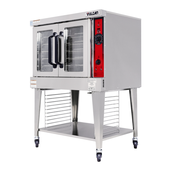
VC4GD WITH ROAST & HOLD SHOWN
This Manual is prepared for the use of trained Vulcan Service
Technicians and should not be used by those not properly qualified. If
you have attended a Vulcan Service School for this product, you may be
qualified to perform all the procedures described in this manual.
This manual is not intended to be all encompassing. If you have not
attended a Vulcan Service School for this product, you should read, in
its entirety, the repair procedure you wish to perform to determine if you
have the necessary tools, instruments and skills required to perform the
procedure. Procedures for which you do not have the necessary tools,
instruments and skills should be performed by a trained Vulcan Service
Technician.
Reproduction or other use of this Manual, without the express written
consent of Vulcan, is prohibited.
For additional information on Vulcan-Hart Company or to locate an authorized parts
and service provider in your area, visit our website at www.vulcanhart.com.
A product of VULCAN-HART
SERVICE MANUAL
VC4G & VC6G SERIES
GAS CONVECTION OVENS
MODEL
VC4GS
VC4GD
VC4GC
VC6GS
VC6GD
VC6GC
- NOTICE -
FULL SIZE
ML
126610
126611
136494
126612
126613
136495
LOUISVILLE, KY 40201-0696
F24682 (Rev. B, October 2007)
Advertisement
Table of Contents

Related Manuals for Vulcan-Hart VC4GC


Summary of Contents for Vulcan-Hart VC4GC
- Page 1 This Manual is prepared for the use of trained Vulcan Service Technicians and should not be used by those not properly qualified. If you have attended a Vulcan Service School for this product, you may be qualified to perform all the procedures described in this manual.
-
Page 2: Table Of Contents
Oven Doors and Bearings (Independent Doors) ........ - Page 3 VC4GC, VC6GC (Roast & Hold Standard on Computer Model) ......46...
-
Page 4: General
30.5" Mechanical (KX) 26.5" Solid State VC4GD 30.5" Solid State VC6GD VC4GC 26.5" Computer 30.5" Computer VC6GC 1. Simultaneous doors are optional (with or w/o window). 2. Stainless steel doors w/o window (standard). 3. Stainless steel doors with window (standard). -
Page 5: Removal And Replacement Of Parts
Remove three (3) screws on the right side which secure the control panel then pull the panel away from the oven. NOTE: If the oven has a mechanical (KX type) thermostat, it must be removed from the control panel first, before removing the control panel. -
Page 6: Control Panel Components
Removable Components Procedure Remove the control panel as outlined under COVERS AND PANELS. Remove the component being replaced. Reverse the procedure to install the replacement component, then check oven for proper operation. F24682 (Rev. B, October 2007) Page 6 of 68... -
Page 7: Component Panel Components
COVERS AND PANELS. Disconnect the wire leads to the component being replaced. Remove the component. Reverse the procedure to install the replacement component and check oven for proper operation. Page 7 of 68 F24682 (Rev. B, October 2007) -
Page 8: Temperature Probe (Vc4Gd/6Gd)
Push the probe through the opening in cavity side wall and into the control panel area. NOTE: The hole in the oven cavity wall does not line up straight with the oven cavity outer shell, therefore the probe must be removed at an angle. -
Page 9: Gas Orifice
Remove the bottom front cover as outlined under COVERS AND PANELS. Remove the bolts securing the gas manifold to the oven and place the manifold to the side. Remove the gas orifice from the spud on the manifold and replace with the correct orifice for the given altitude. -
Page 10: Ignition Control Module
Loosen the bolts securing the valve and bracket assembly then remove the screws securing the valve to the bracket. Reverse the procedure to install the replacement gas valve. NOTE: Clean the pipe threads and apply pipe joint compound to threads. Any pipe joint compound used, must be resistant to the action of propane gases. -
Page 11: Blower And Motor
Reverse the procedure to install the assembly and check for proper operation. NOTE: Check to ensure the spark gap distance is approximately 1/8". If the gap appears to be excessive or poor sparking is occurring then adjust. BLOWER AND MOTOR Shut off the gas before servicing the unit. -
Page 12: Oven Doors And Bearings (Independent Doors)
Remove the nuts that secure the motor mounting plate to the rear wall. Place a piece of cardboard on the bottom of the oven cavity to protect its surface from any damage during motor assembly removal. Pull the motor assembly into the oven cavity and place it on the cardboard. -
Page 13: Oven Doors (Simultaneous Doors)
Reverse procedure to install door assembly and check for proper adjustment as outlined under DOOR ADJUSTMENT and DOOR SWITCH ADJUSTMENT in SERVICE PROCEDURES AND ADJUSTMENTS. OVEN DOORS (SIMULTANEOUS DOORS) Assembly Removal Remove the top front cover and bottom front cover as outlined under COVERS AND PANELS. -
Page 14: Roller Latch Assembly
DOOR SWITCH ADJUSTMENT in SERVICE PROCEDURES AND ADJUSTMENTS. Disassembly Remove the door assembly as outlined in OVEN DOORS (SIMULTANEOUS) under ASSEMBLY REMOVAL. Remove the door chain by loosening one of the turnbuckles. Loosen the set screw on the sprocket of door being replaced. -
Page 15: Door Catch Ball Assembly (Independent Doors)
DOOR CATCH BALL ASSEMBLY (INDEPENDENT DOORS) NOTE: For units with serial number starting with 48 made before 8/13/07 and serial number starting with 54 made before 8/27/07. Remove the top front cover as outlined under COVERS AND PANELS. Remove the screws that secure the door catch assembly. -
Page 16: Door Switch
NOTE: The hole in the oven cavity wall does not line up straight with the oven cavity outer shell, therefore the probe must be removed at an angle. -
Page 17: Interior Lights
Remove the socket from the oven. Attach the lead wires to the replacement socket. Insert the socket into the hole in the oven and push until the socket is held in place by the retaining tabs. Install the light bulb and lens. -
Page 18: Cooling Fan
NOTE: The fan must be installed so air is pulled from the rear of the oven and blown into the control area. The arrow on the fan body indicates AIR FLOW direction and should be pointing toward the controls. -
Page 19: Service Procedures And Adjustments
Rotate the knob to the lowest temperature setting then back to 350°F. Repeat the average temperature calculation in step 7. NOTE: Allow the oven to cycle at least two times between adjustments before performing the calculation. If the above adjustment cannot be obtained, replace the temperature control and check calibration. -
Page 20: Mechanical Thermostat Calibration (Vc4Gs/6Gs)
Replace the knob and repeat step 7 until the average temperature is within tolerance. F24682 (Rev. B, October 2007) NOTE: Allow the oven to cycle at least two times between adjustments before performing the calculation. If the above adjustment can not be obtained, install a replacement thermostat and check calibration. -
Page 21: Temperature Probe Test (Vc4Gd/6Gd)
COVERS AND PANELS. Place a shielded thermocouple in the geometric center of the oven cavity and determine the temperature in the oven cavity. Remove the probe lead wires from the solid state temperature control. -
Page 22: Gas Pressure Adjustment
OHMS* Remove adjustment screw cap from the gas valve and turn gas supply to the oven back on. Plug the unit in and turn the power switch ON. Set the temperature control to its highest setting and allow burner to ignite. -
Page 23: Verification Of Spark At Ignitor
3/16" from the oven frame (bare metal surface). NOTE: It is critical that the cable be held 3/16" away from the surface of the oven frame or sparking may not occur even though the sparking circuit is functioning properly. -
Page 24: Blower Adjustment
BLOWER ADJUSTMENT Shut off the gas before servicing the unit. Remove the blower motor and mounting assembly by following steps 1 through 7 as outlined under BLOWER AND MOTOR in REMOVAL AND REPLACEMENT OF PARTS. Loosen the motor mounting bolts. Adjust the motor position until the blower is parallel to and 1/4 inch away from the motor mounting plate. -
Page 25: Door Adjustment
DOOR ADJUSTMENT Check the doors to make sure they have an equal gap between them and that the vertical edge of the door is parallel to the vertical door seal. If the doors are not positioned in this manner, adjust the doors as described. Remove the top front cover. -
Page 26: Door Catch Ball Adjustment (Independent Doors)
Each oven door should open with a force of 8 to 25 pounds when pulled at the handle. The adjustments must allow the doors to remain closed during normal operation and allow opening without exertion by the user. DOOR CATCH BALL... -
Page 27: Door Chain Adjustment (Simultaneous Doors)
DOOR CHAIN ADJUSTMENT (SIMULTANEOUS DOORS) Introduction When the oven doors are in proper adjustment, as the doors come together, the right door will lead the left door in closing by about 1/4 inch. The doors will feel like they are self closing the last 1/2 inch of travel. -
Page 28: Computer Control (Vc4Gc/Vc6Gc)
NOTE: Use the setup mode to verify that the control is configured to the factory settings which result in the proper operation of the oven. If the CAL1 parameter is other than zero, determine if it is still needed before resetting to zero. See COMPUTER CONTROL CALIBRATION (VC4GC/VC6CG). -
Page 29: Computer Control Calibration (Vc4Gc/Vc6Gc)
5°F tolerance. Exit the setup mode. Allow the oven to cycle at least two times between adjustments. If the temperature variance still differs more than 5°F from the set point, verify the correct calibration offset value was entered and retained. -
Page 30: Electrical Operation
Roast & Hold Timer ... . When the function switch (S3) is set to ROAST & HOLD, this timer must Door Switch ....Allows the oven to operate when the doors are closed but stops the oven Blower Motor . - Page 31 Computer Control (VC4GC/6GC) ....Monitors temperature sensor and regulates the oven cavity temperature by SSR1 & SSR2 (VC4GC/6GC) ..When SSR1 is energized by computer control, connects power to blower Ignition Control Module .
-
Page 32: Component Location
FULL SIZE GAS CONVECTION OVENS - ELECTRICAL OPERATION COMPONENT LOCATION F24682 (Rev. B, October 2007) Page 32 of 68... - Page 33 FULL SIZE GAS CONVECTION OVENS - ELECTRICAL OPERATION VC4GS/6GS - Plug, Socket and Components (Standard Controls) Page 33 of 68 F24682 (Rev. B, October 2007)
- Page 34 FULL SIZE GAS CONVECTION OVENS - ELECTRICAL OPERATION VC4GD/6GD - Plug, Socket and Components (Standard Controls) F24682 (Rev. B, October 2007) Page 34 of 68...
- Page 35 FULL SIZE GAS CONVECTION OVENS - ELECTRICAL OPERATION VC4GS/6GS, VC4GD/6GD - Plug, Socket and Components (Roast & Hold Option) Page 35 of 68 F24682 (Rev. B, October 2007)
- Page 36 FULL SIZE GAS CONVECTION OVENS - ELECTRICAL OPERATION VC4GC/6GC - Plug, Socket and Components (Roast & Hold Standard) F24682 (Rev. B, October 2007) Page 36 of 68...
-
Page 37: Sequence Of Operation
Normal ROAST timer terminal 1, ROAST & HOLD timer terminal 1, transformer primary (T1). NOTE: Power is available to the oven light switch (wire #20) to turn the oven cavity lights ON when the light switch is turned ON; and power is available to the normally open N.O. - Page 38 Power removed from 2 (main) on the gas valve and gas flow to the burner stops. The oven will continue to cycle on the thermostat until the doors are opened or the power switch (S1) is turned to the OFF or COOL DOWN position.
- Page 39 Normal ROAST timer terminal 1, ROAST & HOLD timer terminal 1, transformer primary (T1). NOTE: Power is available to the oven light switch (wire #20) to turn the oven cavity lights ON when the light switch is turned ON; and power is available to the normally open N.O.
- Page 40 ROAST & HOLD time (R & H cooking) expires which allows the oven to go into Hold mode; Power switch (S1) is turned to the OFF or COOL DOWN position or the doors are opened.
-
Page 41: Vc4Gd, Vc6Gd With Roast & Hold Option (Solid State Temperature Control)
(R1). Convection fan motor de-energized and fan stops rotating. The oven will continue to cycle on the hold thermostat until the ROAST & HOLD timer is turned to the OFF position, the function switch (S3) is changed back to ROAST (normal cooking) or the power switch (S1) is turned to the OFF or COOL DOWN position. - Page 42 F24682 (Rev. B, October 2007) valve valve (main) Oven reaches set temperature. The oven will continue to cycle on the temperature control until the doors are opened or power switch (S1) is turned to the OFF or COOL DOWN position.
- Page 43 1, ROAST & HOLD timer terminal 1, transformer primary (T1). NOTE: Power is available to the oven light switch (wire #20) to turn the oven cavity lights ON when the light switch is turned ON; and power is available to the normally open N.O.
- Page 44 ROAST & HOLD time (R & H cooking) expires which allows the oven to go into Hold mode; Power switch (S1) is turned to the OFF or COOL DOWN position or the doors are opened.
- Page 45 Contacts 1 & 3 open, timer motor is de- energized and timing stops. Contacts 1 & 4 close. If the oven was heating, then the gas burner and heat light go out; If the oven was not heating, then the gas burner and heat light remain out.
-
Page 46: Cool Down Cycle (Solid State Temperature Control)
The oven will continue to cycle on the hold thermostat until the ROAST & HOLD timer is turned to the OFF position and the function switch (S3) is change back to ROAST (normal cooking) or the power switch (S1) is turned to the OFF or COOL DOWN position. - Page 47 NOTE: Power at pin 3 is not transferred to other components until computer control is energized and operating conditions are met. Power is available to the oven light switch (S2). Power to terminal 1 on solid state relay 1 (SSR1 -load side) and solid state relay 2 (SSR2 -load side).
- Page 48 Oven READY LIGHT on the control comes Electronic beeper sounds momentarily. The oven will continue to cycle on the computer control until the doors are opened or power switch (S1) is turned to the OFF or COOL DOWN position.
-
Page 49: Cool Down Cycle (Computer Control Model)
The oven will continue to operate in COOL DOWN mode until the power switch (S1) is turned to the OFF or ON position. -
Page 50: Schematics
FULL SIZE GAS CONVECTION OVENS - ELECTRICAL OPERATION SCHEMATICS VC4GS, VC6GS Mechanical (KX) Controls F24682 (Rev. B, October 2007) Page 50 of 68... -
Page 51: Vc4Gs, Vc6Gs Mechanical (Kx) Controls, Roast & Hold Option
FULL SIZE GAS CONVECTION OVENS - ELECTRICAL OPERATION VC4GS, VC6GS Mechanical (KX) Controls, Roast & Hold Option Page 51 of 68 F24682 (Rev. B, October 2007) -
Page 52: Vc4Gd, Vc6Gd Solid State Temperature Control
FULL SIZE GAS CONVECTION OVENS - ELECTRICAL OPERATION VC4GD, VC6GD Solid State Temperature Control F24682 (Rev. B, October 2007) Page 52 of 68... -
Page 53: Vc4Gd, Vc6Gd Solid State Temperature Control, Roast & Hold Option
FULL SIZE GAS CONVECTION OVENS - ELECTRICAL OPERATION VC4GD, VC6GD Solid State Temperature Control, Roast & Hold Option Page 53 of 68 F24682 (Rev. B, October 2007) -
Page 54: Vc4Gc, Vc6Gc Computer Control (Roast & Hold Standard)
FULL SIZE GAS CONVECTION OVENS - ELECTRICAL OPERATION VC4GC, VC6GC Computer Control (Roast & Hold Standard) F24682 (Rev. B, October 2007) Page 54 of 68... - Page 55 FULL SIZE GAS CONVECTION OVENS - ELECTRICAL OPERATION - N O T E S - Page 55 of 68 F24682 (Rev. B, October 2007)
-
Page 56: Wiring Diagrams
FULL SIZE GAS CONVECTION OVENS - ELECTRICAL OPERATION WIRING DIAGRAMS VC4GS, VC6GS Mechanical (KX) Controls F24682 (Rev. B, October 2007) Page 56 of 68... - Page 57 FULL SIZE GAS CONVECTION OVENS - ELECTRICAL OPERATION Page 57 of 68 F24682 (Rev. B, October 2007)
-
Page 58: Vc4Gs, Vc6Gs Mechanical (Kx) Controls, Roast & Hold Option
FULL SIZE GAS CONVECTION OVENS - ELECTRICAL OPERATION VC4GS, VC6GS Mechanical (KX) Controls, Roast & Hold Option F24682 (Rev. B, October 2007) Page 58 of 68... - Page 59 FULL SIZE GAS CONVECTION OVENS - ELECTRICAL OPERATION Page 59 of 68 F24682 (Rev. B, October 2007)
-
Page 60: Vc4Gd, Vc6Gd Solid State Temperature Control
FULL SIZE GAS CONVECTION OVENS - ELECTRICAL OPERATION VC4GD, VC6GD Solid State Temperature Control F24682 (Rev. B, October 2007) Page 60 of 68... - Page 61 FULL SIZE GAS CONVECTION OVENS - ELECTRICAL OPERATION Page 61 of 68 F24682 (Rev. B, October 2007)
-
Page 62: Vc4Gd, Vc6Gd Solid State Temperature Control, Roast & Hold Option
FULL SIZE GAS CONVECTION OVENS - ELECTRICAL OPERATION VC4GD, VC6GD Solid State Temperature Control, Roast & Hold Option F24682 (Rev. B, October 2007) Page 62 of 68... - Page 63 FULL SIZE GAS CONVECTION OVENS - ELECTRICAL OPERATION Page 63 of 68 F24682 (Rev. B, October 2007)
-
Page 64: Vc4Gc, Vc6Gc Computer Control (Roast & Hold Standard)
FULL SIZE GAS CONVECTION OVENS - ELECTRICAL OPERATION VC4GC, VC6GC Computer Control (Roast & Hold Standard) F24682 (Rev. B, October 2007) Page 64 of 68... - Page 65 FULL SIZE GAS CONVECTION OVENS - ELECTRICAL OPERATION Page 65 of 68 F24682 (Rev. B, October 2007)
-
Page 66: Troubleshooting
Certain procedures in this section require electrical test or measurements while power is applied to the machine. Exercise extreme caution at all times. If test points are not easily accessible, disconnect power and follow lockout / tagout procedures, attach test equipment and reapply power to test. -
Page 67: Computer Control Models Only
Error Codes In the display window, the error code will alternate between the code and the oven cavity temperature or dashes if the oven is calling for heat (heat light on). When the condition causing the error is resolved, normal oven operation can resume. - Page 68 CODE & PROBLEM Er06 - Zone 1 A/D underflow error Er07 - Zone 1 A/D overflow error Er10 - Stack overflow error Er11 - Open sensor error Er12 - Shorted sensor F24682 (Rev. B, October 2007) PROBABLE CAUSE • Incorrect sensor type •...