
Related Manuals for VocoPro IR-9000


Summary of Contents for VocoPro IR-9000
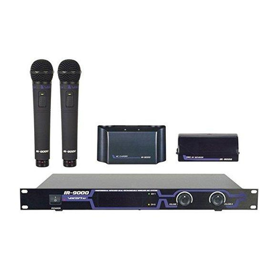
- Page 1 THE SINGER'S ULTIMATE CHOICE IR-9000 Professional Infrared Dual Rechargeable Wireless Mic System...
-
Page 2: Table Of Contents
Table of Contents Listening for a Lifetime...3 Safety Instructions...4 FCC Information ...5 Welcome ...6 Getting Started ...7 Getting Connected...8 Operations ...11 Descriptions and Functions ...12 Troubleshooting ...14 Technical Specs ...15... -
Page 3: Listening For A Lifetime
Now itʼs time to consider how you can maximize the fun and excitement your equipment offers. VocoPro and the Electronic Industries Associationʼs Consumer Electronics Group want you to get the most out of your equipment by playing it at a safe level. One that lets the sound come through loud and clear without annoying blaring or distortion and, most importantly, without affecting your sensitive hearing. -
Page 4: Safety Instructions
Safety instructions CAUTION RISK OF SHOCK CAUTION: To reduce the risk of electric shock, do not remove cover (or back). No user-serviceable parts inside. Only refer servicing to qualified service personnel. Explanation of Graphical Symbols The lightning flash & arrowhead symbol, within an equilateral triangle, is intended to alert you to the presence of danger. -
Page 5: Fcc Information
UNIT!: This product, when installed as indicated in the instructions contained in this manual, meets FCC requirements. Modifications not expressly approved by Vocopro may void your authority, granted by the FCC, to use this product. 2. IMPORTANT: When connecting this product to accessories and/or another product use only high quality shielded cables. -
Page 6: Welcome
Club VocoPro for Karaoke news and events, chat rooms, club directories and even a KJ Service directory! We look forward to hearing you sound like a PRO, with VocoPro, your ultimate choice in Karaoke entertainment. Please record the model number and serial number below, for easy reference, in case of loss or theft. These numbers are located on the rear panel of the unit. -
Page 7: Getting Started
Getting Started When unpacking your IR-9000 we recommend that you keep the original receipt or invoice, box and packing materials in case the product ever needs to be shipped for warranty repair or any other purpose. Warranty Information The IR-9000 is covered under a 1-Year Limited Warranty. For detailed warranty information please visit www.vocopro.com/warranty_standard.html... -
Page 8: Getting Connected
Getting Connected Connecting the Power Supplies The IR-9000 includes two power supplies, one for the receiver unit (AC 110V) and one for the microphone charger (AC 110V). Surge Protector Recommended VocoPro recommends that you use a surge protector with all of your products to prevent damage caused by unpredictable power surges. - Page 9 Connecting to a Mixer, amplifi er or other audio input device The IR-9000 allows you to either connect each microphone channel individually to separate channels using the CH.1 and CH.2 outputs (Fig. C) or both microphone channels together through the MIXED output (Fig. D).
- Page 10 Getting Connected cont. Connecting the External Infrared Sensor(s) The IR-9000 can connect up to two external infrared sensors. One is included and a second one can be purchased from your nearest VocoPro dealer. 1. Connect The RCA end of the sensor to one of the External Sensor Inputs on the rear panel of the reciever unit 2.
-
Page 11: Operations
Operations Turning on the IR-9000 Receiver Unit Make sure all cables and power supplies are connected correctly and firmly. 1. Press the power switch ON to turn the power on 2. Press the power switch OFF to turn the power off Microphones 1. -
Page 12: Descriptions And Functions
3. LED Channel Indicators - Each of these two LED indicators will light up when the corresponding microphone is switched on and an infrared connection is made to the IR-9000. The indicator(s) will remain lit as long as the infrared connection is maintained. - Page 13 Descriptions and Functions cont. Microphone 1. Power Switch - Turns the microphone’s power on and off 2. Power indicator LED - Indicates when the microphone’s power is on. 4. IR Transmitter - This lens emits the infrared signal to the sensor on the receiver. Note: Keep hands away from this part of the microphone, as it may block the infrared signal.
-
Page 14: Troubleshooting
• Make sure all cables are fully inserted into the correct inputs and outputs. See the Getting Connected section in this manual for detailed instructions on setting up the IR-9000. • Make sure all of the volume controls on the IR-9000 and on your other components are turned up •... -
Page 15: Technical Specs
Technical Specifications Transmitter Working Voltage: DC 2-3V Working Frequency: A: 2.08MHz, B: 2.54MHz Continuous working time: 5hr Receiver Power Consumption: 7W Audio Output: 600Ω/300mV S/N:>100dB Frequency response: 45Hz-15KHz ± 3dB Working Distance(forward): >10m Working Range: >30m² Power Adapter Input: AC 110V 60Hz Output: DC 15V 500mA Charger Charge voltage/current: DC 3.2V 350mA x2... - Page 16 THE SINGER'S ULTIMATE CHOICE IR-9000 owner’s manual © VocoPro 2007 v1.0 www.vocopro.com...