
Related Manuals for Toro 25545T


Summary of Contents for Toro 25545T
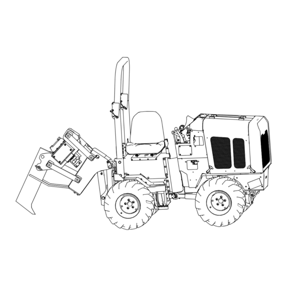
- Page 1 Operator’s Manual Maxi Sneaker 370 Model—Serial Range 25530T—323000000 and Up 25545T—324000000 and Up 25546T—324000000 and Up *3467-222* A 3467-222A Original Instructions (EN)
- Page 2 Because in some areas there are local, state, or federal regulations requiring that a spark arrester be used on the engine of this machine, a spark arrester is available as an option. If you require a spark arrester, contact your Authorized Service Dealer. Genuine Toro spark arresters are approved by the USDA Forestry Service.
-
Page 3: Table Of Contents
Table of Contents Disclaimers and Regulatory Information....................2 Chapter 1: Introduction........................1–1 Intended Use ............................. 1–1 Getting Help............................1–1 Manual Conventions........................1–2 Safety Alert Classifications......................1–2 Chapter 2: Safety..........................2–1 General Safety ..........................2–1 Safety and Instructional Decals ....................2–2 Decal Locations .......................... - Page 4 Plow ............................... 5–10 Trench ............................5–12 Trench Systems and Equipment..................... 5–14 Drill ..............................5–16 After Operation..........................5–19 After Operation Safety....................... 5–19 Finishing the Job......................... 5–19 Chapter 6: Transport..........................6–1 Hauling the Machine ........................6–1 Trailer Requirements ........................6–1 Loading the Machine ........................6–2 Tie-Down Points..........................
- Page 5 Adjusting the Parking Brake..................... 7–17 Adjusting the Neutral Position ....................7–17 Cleaning the Controls Linkage Assembly................7–18 Hydraulic System Maintenance ....................7–19 Hydraulic System Safety......................7–19 Hydraulic Fluid Specifications ....................7–19 Checking the Hydraulic Fluid Level..................7–20 Changing the Hydraulic Fluid ....................7–20 Changing the Hydraulic Filter ....................
-
Page 6: Chapter 1: Introduction
Whenever you need service, genuine Toro parts, or additional information, contact an Authorized Service Dealer or Toro Customer Service and have the model and serial numbers of your product ready. These numbers are located on the serial plate on your product . -
Page 7: Manual Conventions
Manual Conventions This manual identifies potential hazards and has safety messages identified by the safety- alert symbol, which signals a hazard that may cause serious injury or death if you do not follow the recommended precautions. G405934 This manual uses 2 words to highlight information. Important calls attention to special mechanical information and Note emphasizes general information worthy of special attention. -
Page 8: Chapter 2: Safety
Chapter 2 Safety General Safety WARNING Contacting underground utilities can cause death or serious injury. Locate and verify underground utilities before digging or drilling. • Before operating any equipment, review emergency procedures and check that all safety precautions have been taken. •... -
Page 9: Safety And Instructional Decals
Safety and Instructional Decals Safety decals and instructions are easily visible to the operator and are located near any area of potential danger. Replace any decal that is damaged or missing. Decal Part: 147-5628 Fuel—Diesel s_decal147-5628 Decal Part: 147-5630 Hydraulic fluid; Read the Operator’s Manual. - Page 10 Decal Part: 147-5637 Lower the trencher; raise the plow. Raise the trencher; lower the plow. decal147-5637 Decal Part: 147-5638 Vibration Fast Neutral decal147-5638 Decal Part: 147-5642 Oil level decal147-5642 Safety: Safety and Instructional Decals Page 2–3 3467-222 A...
- Page 11 Decal Part: 147-5646 Warning—Read the Operator’s Manual before starting the machine. decal147-5646 Decal Part: 147-5652 Parking brake decal147-5652 3467-222A Page 2–4 Safety: Safety and Instructional Decals...
- Page 12 Decal Part: 147-5639 decal147-5639 Belt Hydraulic fluid filter Engine oil filter Hydraulic fluid Transmission oil Engine air filter Lubrication Engine air filter Vibrator box oil level Fuel filter Read the Operator’s Manual. Fuel filter Decal Part: 147-5805 Throttle Fast Slow decal147-5805 Safety: Safety and Instructional Decals Page 2–5...
-
Page 13: Decal Locations
Decal Locations G414366 147-5651 147-5647 147-5641 147-5627 147-5645 147-5648 147-5644 147-5629 147-5650 Decal Part: 147-5647 Crushing hazard—stay away form articulated joints. decal147-5647 3467-222A Page 2–6 Safety: Safety and Instructional Decals... - Page 14 Decal Locations (continued) Decal Part: 147-5627 decal147-5627 Explosion hazard—Do not use starting fluid. Decal Part: 147-5645 Engine—Off Engine—Run Engine—Start decal147-5645 Decal Part: 147-5629 Explosion hazard—Call before you dig. decal147-5629 Safety: Safety and Instructional Decals Page 2–7 3467-222 A...
- Page 15 Decal Locations (continued) Decal Part: 147-5650 Tipping hazard—Raise and lock the roll bar and wear a seatbelt. decal147-5650 Decal Part: 147-5651 Burn hazard—keep away from hot surfaces. decal147-5651 3467-222A Page 2–8 Safety: Safety and Instructional Decals...
- Page 16 Decal Locations (continued) Decal Part: 147-5641 Tie down decal147-5641 Decal Part: 147-5648 Cutting hazard of the hand—Keep your hands away from the machine. decal147-5648 Decal Part: 147-5644 Warning—Wear hearing protection decal147-5644 Safety: Safety and Instructional Decals Page 2–9 3467-222 A...
-
Page 17: Plow Decal Locations
Plow Decal Locations G414368 147-5641 147-5649 Decal Part: 147-5649 Cutting hazard of the hand—Keep bystanders away. decal147-5649 3467-222A Page 2–10 Safety: Safety and Instructional Decals... -
Page 18: Trencher Safety Decal Locations
Plow Decal Locations (continued) Decal Part: 147-5641 Tie down decal147-5641 Trencher Safety Decal Locations G434864 Decal 147-5807 Decal 147-5641 Decal Part: 147-5641 Tie down decal147-5641 Safety: Safety and Instructional Decals Page 2–11 3467-222 A... - Page 19 Trencher Safety Decal Locations (continued) Decal Part: 147-5654 Attachment selector lever. decal147-5654 Decal Part: 147-5655 Trencher chain direction selector lever. 147-5655 Decal Part: 147-5807 Cutting/dismemberment hazard, trencher—keep at least 2 m (6 ft) away. decal147-5807 3467-222A Page 2–12 Safety: Safety and Instructional Decals...
-
Page 20: Hydra Borer Safety Decal Location
Hydra Borer Safety Decal Location Decal147-5746 G434640 Decal Part: 147-5746 Rotating shaft hazard; keep away from moving parts. decal147-5746 Decal Part: 147-5747 decal147-5747 Safety: Safety and Instructional Decals Page 2–13 3467-222 A... - Page 21 Hydra Borer Safety Decal Location (continued) Decal Part: 147-5748 Push the lever forward to rotate the drill clockwise; Pull the lever rearward to rotate the drill counterclockwise. decal147-5748 3467-222A Page 2–14 Safety: Safety and Instructional Decals...
-
Page 22: Chapter 3: Preparation
Chapter 3 Preparation Jobsite Preparation A successful job begins before working. The first step in planning is reviewing information already available about the job and jobsite. Reviewing the Job Plan Review the blueprints or other plans. Check for information about existing or planned structures, elevations, or proposed work that may be taking place at the same time. -
Page 23: Locating Utilities
Identifying Hazards (continued) – Light poles – Sunken ground • Traffic • Access • Soil type and condition • Loose material such as fencing or cable Locating Utilities 1. Notify One-Call Services; mark the proposed path with white paint and have the underground utilities located before working. -
Page 24: Classified Jobsite Precautions
Classifying the Jobsite (continued) Classified Jobsite Precautions Electric Precautions • Expose the line by careful hand digging or soft excavation. • Have the service shut down while work is in progress. • Have the electrical company test the lines before returning them to service. Natural Gas Precautions Position equipment upwind from the gas lines and use one or more of these methods: •... -
Page 25: Equipment Preparation
• Use equipment carefully. Stop operation and investigate anything that does not look or feel right. Equipment Preparation Preparation checklists are available at www.Toro.com. Installing Counterweights Install counterweights as needed for attachments. Mounting the Fire Extinguisher Mount a fire extinguisher near the engine but away from possible points of ignition where shown. -
Page 26: Chapter 4: Product Overview
Chapter 4 Product Overview Plow Plow control Engine oil filter Air filter Engine oil cap Fuel water separator Diesel particulate filter Battery Coolant expansion tank Battery disconnect switch Hydraulic tank G402840 Product Overview Page 4–1 3467-222 A... -
Page 27: Controls
Controls G400533 Key switch Display Traction control lever Throttle Parking brake Low speed traction control Attachment control lever USB port Auxiliary port Throttle G407271 3467-222A Page 4–2 Product Overview: Controls... - Page 28 Battery Disconnect Switch Off—to de-energize the machine electrically On—to energize the machine electrically G419389 Key Switch Stop engine Run engine Start engine G407265 Parking Brake Disengage Engage g407270 Product Overview: Controls Page 4–3 3467-222 A...
- Page 29 Attachment Control Lever Push the lever forward to RAISE plow or the trencher. LOWER G407266 Pull the lever rearward to LOWER plow or the trencher. RAISE G407267 3467-222A Page 4–4 Product Overview: Controls...
- Page 30 Driving Controls G407268 Product Overview: Controls Page 4–5 3467-222 A...
-
Page 31: Attachment Controls
Attachment Controls G429253 Digging chain control Drilling attachment control Attachment selector control Plow vibrator control Attachment Controls Descriptions Icon Icon Name Description Drilling attachment To rotate the drill clockwise, push toward the front of the control machine. To rotate the drill counterclockwise, pull toward the back of the machine. -
Page 32: Display
Attachment Controls Descriptions (continued) Icon Icon Name Description Digging chain control To start chain, push toward the front of the machine. To reverse chain, pull toward the back of the machine. Plow vibrator control To start the plow vibration, push toward right side of machine. -
Page 33: Indicator Descriptions
Indicators (continued) Indicator Descriptions Icon Icon Name Description Engine caution/stop Lights yellow when the engine needs attention. indicator Lights red when the operator needs to stop the engine. Hydraulic fluid Lights when the hydraulic fluid temperature is too high. temperature indicator Engine oil pressure Lights when the engine oil pressure is too low. -
Page 34: Gauges
Gauges G400645 Engine load percentage Tachometer Clock Hourmeter Engine coolant temperature gauge Fuel gauge Voltmeter Gauges Descriptions Icon Icon Name Description Tachometer Displays the engine speed. Clock Displays the time. Engine coolant Displays the engine coolant temperature. temperature gauge Voltmeter Displays the machine voltage. -
Page 35: Keys
Keys G40064 Main menu key Hide/Recall diagnostics key Keys Descriptions Icon Icon Name Description Hide/Recall To hide a diagnostic message, press twice. diagnostics key To recall, press once. Main menu key To select the main menu, press. 3467-222A Page 4–10 Product Overview: Display... -
Page 36: Specifications
Specifications G409123 Note: Specifications and design are subject to change without notice. Width (with 23 inch tires in the narrow 92.7 cm (36.5 inches) configuration) Width (with 23 inch tires in the wide 119 cm (47 inches) configuration) Width (with 26 inch tires in the narrow 103.6 cm (40.8 inches) configuration) Width (with 26 inch tires in the wide... -
Page 37: Attachments/Accessories
Attachments/Accessories A selection of Toro approved attachments and accessories is available for use with the machine to enhance and expand its capabilities. Contact your Authorized Service Dealer or authorized Toro distributor or go to www.Toro.com for a list of all approved attachments and accessories. -
Page 38: Chapter 5: Operation
Chapter 5 Operation Before Operation Before Operation Safety • Never allow children or untrained people to operate or service the machine. Local regulations may restrict the age or require certified training of the operator. The owner is responsible for training all operators and mechanics. •... -
Page 39: Fuel Safety
Before Operation Safety (continued) – To help prevent trailer sway, load the trailer so that 10 to 15 percent of the total vehicle weight (equipment plus trailer) is on the tongue. Fuel Safety • Use extra care when handling fuel. It is flammable and its vapors are explosive. Keep heat, flames, sparks, and other ignition sources away. - Page 40 Fuel (continued) Use only clean, fresh diesel fuel or biodiesel fuels. Purchase fuel in quantities that can be used within 180 days to ensure fuel freshness. IMPORTANT Use only ultra-low sulphur diesel fuel. Fuel with higher rates of sulfur degrades the diesel oxidation catalyst (DOC), which causes operational problems and shortens the service life of engine components.
-
Page 41: Start Interlock System
Fuel (continued) Filling the Fuel Tank 1. Park the machine on a level surface, shut off the engine, and allow it to cool. 2. Clean around the fuel tank cap and remove it. 3. Add fuel to the fuel tank until the level is just below the bottom of the filler neck. Note: This space in the tank allows fuel to expand. - Page 42 – Lower the attachments. – Shut off the engine and remove the key. • Use only Toro-approved attachments and accessories. Attachments can change the stability and the operating characteristics of the machine. • Stop the attachment when you are not working.
- Page 43 During Operation Safety (continued) • Most electric strikes are not noticeable, but indications of a strike include: – Power outage – Smoke – Explosion – Popping noises – Arcing electricity If any of these occur, assume an electric strike has occurred. If you suspect that an electric line is damaged, do not move and take the following actions.
-
Page 44: Slope Safety
During Operation Safety (continued) • Immediately move the battery disconnect switch (if equipped and accessible) to the DISCONNECT position. • If the fire is small and a fire extinguisher is available, extinguish the fire. • If you cannot extinguish the fire, leave the area as soon as possible and contact emergency personnel. -
Page 45: Adjusting The Roll Bar
Slope Safety (continued) • Follow procedures and rules for operating on slopes. These procedures must include surveying the site to determine which slopes are safe for machine operation. Always use common sense and good judgment when performing this survey. • Avoid starting or stopping on a slope. If the machine loses traction, proceed slowly, straight down the slope. -
Page 46: Starting And Shutting Off The Engine
Adjusting the Roll Bar (continued) WARNING There is no rollover protection when the roll bar is lowered. • Lower the roll bar only when absolutely necessary for hauling or parking. • Do not wear the seat belt when the roll bar is lowered. •... -
Page 47: Plow
Starting and Shutting Off the Engine (continued) Shutting Off the Machine 1. Move the machine to a level surface. 2. Engage the parking brake. 3. Lower any attachments to the ground. 4. Set all controls to N EUTRAL 5. Move the throttle lever to S 6. - Page 48 Plow (continued) Attaching the Product 1. Insert the material into the pulling grip. 2. Tape the grip with duct tape. 3. Remove the cable guide. G425616 4. Feed the cable through the tube from the top to the bottom. 5. Replace the cable guide and tighten the fasteners.
-
Page 49: Trench
Plow (continued) 5. Reduce the attachment speed to a point with the least machine vibration and the highest ground drive speed possible. 6. Check the installed product for any damage during plowing. Finishing the Job 1. When the installation is complete, move the ground drive control to N EUTRAL 2. - Page 50 Trench (continued) 1. Select the trencher chain direction. The digging chain will move. DANGER Contact with moving digging teeth will cause death or serious injury. Stay at least 1.8 m (6 feet) away. To help avoid injury: • Allow 1 m (3 feet) between the digging teeth and an obstacle. The machine may jerk when digging starts.
-
Page 51: Trench Systems And Equipment
Trench (continued) 3. Raise the boom. 4. As the boom clears the top of the trench, set the trencher control lever to N EUTRAL 5. Drive a short distance away from the work site. 6. Engage the parking brake. 7. Shut off the machine. Trench Systems and Equipment Chain Selection These charts are meant as a guideline only. - Page 52 Trench Systems and Equipment (continued) Chain and Tooth Maintenance • Always replace sprockets at the same time as the digging chain. The sprockets and the chain are designed to work together. Replacing one without the other will cause premature wear of the new part. •...
-
Page 53: Drill
Trench Systems and Equipment (continued) Chain Type Chain Type Features 2–pitch More teeth for smoother cutting 4–pitch Standard chain Alternating side bar Prevents soil compaction on chain Bolt-on adapters Allows easy configuration changes Combination Provides pick and shovel effect Drill Digging the Trenches 1. - Page 54 Drill (continued) WARNING Underground utilities contact can cause death or serious injury. Locate and verify underground utilities before digging or drilling. To help avoid injury: Only operate the drilling attachment if the bore path is more than 3 m (10 ft) from any underground hazard. IMPORTANT Boring is a 2 person operation.
- Page 55 Drill (continued) Backreaming the Hole Sometimes it is necessary to drill a pilot hole first, then enlarge the hole to accommodate larger product. As a general rule, the final hole should be 1.5 times larger than the diameter of the product being installed. The number of passes needed depends on the soil conditions.
-
Page 56: After Operation
After Operation After Operation Safety • Shut off the engine, remove the key, wait for all movement to stop, and allow the machine to cool before adjusting, cleaning, storing, or servicing it. • Do not touch parts that may be hot from operation. Allow them to cool or wear gloves before attempting to maintain, adjust, or service the machine. -
Page 57: Chapter 6: Transport
Chapter 6 Transport Hauling the Machine Use a heavy-duty trailer or truck to haul the machine. Use a full-width ramp. Ensure that the trailer or truck has all the necessary brakes, lighting, and marking as required by law. Please carefully read all the safety instructions. Knowing this information could help you or bystanders avoid injury. -
Page 58: Loading The Machine
Trailer Requirements (continued) Full-width ramp in stowed position Ramp is at least 4 times as long as the height of the trailer or truck bed to the ground H = height of the trailer or truck bed to the ground Trailer G229507s Loading the Machine... -
Page 59: Tie-Down Points
Loading the Machine (continued) 1. Connect the trailer to the towing vehicle and connect the safety chains. 2. If applicable, connect the trailer brakes. 3. Lower the ramp. 4. Start the engine. 5. Raise the trencher boom, if attached, but keep it low. 6. -
Page 60: Unloading The Machine
Tying Down the Machine (continued) G418233 Distance Metric 45.7 to 76.2 cm 18 to 30 inches Unloading the Machine WARNING Crushing weight could cause death or serious injury. Stay away. To help avoid injury: • Unload the unit with the engine in low idle and the boom as low as possible. •... -
Page 61: Retrieving The Machine
Retrieving the Machine Under normal conditions, do not tow the machine. If the machine becomes disabled and retrieval is needed: • Do not tow the machine for more than 180 m (200 yd). • Tow the machine at less than 1.5–3.0 km/h (1–2 mph). •... -
Page 62: Chapter 7: Maintenance
Chapter 7 Maintenance Maintenance Safety • Making unauthorized modifications to the machine may result in it no longer meeting safety standards and regulations and/or not functioning properly. Allow only competent and trained personnel to modify the machine according to the applicable standards, regulations, and machine design functionality and requirements. -
Page 63: Recommended Maintenance Schedule
Recommended Maintenance Schedule Maintenance Maintenance Procedure Service Interval After the first 10 Check the Exhaust Clamp hours After the first 25 Change the Hydraulic Filter hours Change the Engine Oil After the first 50 hours Check the Drive Belt Tension After the first 250 Change the Hydraulic Fluid hours... - Page 64 Maintenance Maintenance Procedure Service Interval Change the Fuel Filter Replace the Drive Belt Check the Roll Bar Change the Engine Coolant Every 1,000 hours Change the Axle Oil Every 1000 hours or Change the Hydraulic Fluid yearly, whichever Change the Gearbox Oil comes first Monthly Clean the Controls Linkage Assembly...
-
Page 65: Lubrication
Lubrication Greasing the Drive Shaft and U-Joint Grease Type: General purpose grease. 1. Clean the grease fittings with a rag. 2. Pump grease into the fittings until grease begins to ooze out of the bearings (approximately 3 pumps). G462130 3. Wipe up any excess grease. Greasing the Plow Grease Type: General purpose grease. -
Page 66: Engine Maintenance
Engine Maintenance Engine Safety • Shut off the engine before checking the oil or adding oil to the crankcase. • Do not change the engine governor setting or overspeed the engine. • Keep your hands, feet, face, clothing, and other body parts away from the muffler and other hot surfaces. -
Page 67: Checking The Engine Oil
Changing the Air Filter (continued) 1. Inspect the air cleaner body for damage. Replace or repair any damaged components. 2. Remove the cover 3. Remove the primary and secondary elements. 4. Wipe the inside of the housing and cover G416155 5. -
Page 68: Checking The Exhaust Clamp
Checking the Exhaust Clamp Check the clamp and lock screw on the exhaust extension to ensure that it is tight. Checking the Exhaust System Check for any loose or damaged components. Check the heat shields near the battery, starter, and air cleaner and replace them if they are damaged. Fuel System Maintenance Checking the Fuel Lines Check the fuel lines and connections for any signs of deterioration, damages, leaks, or loose... -
Page 69: Draining The Fuel/Water Separator
Draining the Fuel/Water Separator 1. Place a container under the fuel filter. 2. Loosen the filter canister drain valve. 3. After the water has drained, tighten the drain valve. G433380 Electrical System Maintenance Electrical System Safety • Disconnect the battery before repairing the machine. Disconnect the negative terminal first and the positive last. -
Page 70: Checking The Battery
Electrical System Safety (continued) WARNING Fire or explosion from explosive hydrogen gas can cause death or serious injury. Keep heat, flames, sparks, and other sources of ignition away. To help avoid injury: • Use a single 12 V maximum source for charging. Never connect the battery to rapid chargers or dual batteries. - Page 71 Charging the Battery (continued) 3. Connect the red positive (+) jumper cable clamp to the positive (+) post of the battery in the disabled machine. 4. Connect the other red positive (+) jumper cable clamp to the positive (+) post of battery in the service vehicle.
- Page 72 Charging the Battery (continued) 9. Remove the black negative (-) cable clamp from the disabled machine or frame ground. 10. Remove the red positive (+) cable clamp from the disabled machine. 11. Turn the battery disconnect to O G289503S Maintenance: Electrical System Maintenance Page 7–11 3467-222 A...
-
Page 73: Drive System Maintenance
Drive System Maintenance Tire Specifications Torque (in a crossing pattern) 108 to 135 N•m (80 to 100 ft-lbs) Tire Size Pressure Ply Rating 23 x 10.5 x 12 26 x 12 x 12 Note: Use a lower tire pressure when operating in sandy soil conditions to provide better traction in the loose soil. -
Page 74: Gearbox Specifications
Gearbox Specifications Transmission oil SAE 80W90 limited slip oil Capacity 0.47 L (0.5 qt) Axle oil SAE 80W90 API classification level GL5 Front axle capacity 2.4 L (2.5 US qt) Rear axle capacity 2.4 L (2.5 US qt) Checking the Gearbox Oil 1. -
Page 75: Changing The Gearbox Oil
Changing the Gearbox Oil 1. While the oil is warm, remove the plug drain the tank. 2. Install the plug. 3. Replace the filter each time the oil is changed. 4. Add fluid at the fill point until the oil level is even with the bottom of the fill plug. -
Page 76: Changing The Engine Coolant
Checking the Engine Coolant Level (continued) 1. Remove the radiator and expansion tank caps. 2. Check the coolant level in the radiator. Note: Fill the radiator to the top of the filler neck and the expansion tank to the full mark. 3. -
Page 77: Belt Maintenance
Belt Maintenance Checking the Drive Belt Tension The belt is properly tensioned when it moves about 7–10 mm (1/4–3/8 inch) when you push it at the long span. Check the belt for excessive slack, damage, or wear. G418844 Adjusting the Drive Belt 1. -
Page 78: Replacing The Drive Belt
Replacing the Drive Belt 1. Loosen the four alternator bolts 2. Replace the fan belt 3. Adjust the belt tension as needed. 4. Tighten the bolts. 5. Check the tension. G416158 Controls Maintenance Adjusting the Parking Brake 1. Shut off the engine. 2. -
Page 79: Cleaning The Controls Linkage Assembly
Adjusting the Neutral Position (continued) 3. Adjust the adjustment nut depending on which way the machine is moving: • If the machine is moving forward, turn the nut counter clockwise. • If the machine is moving rearward, turn the nut clockwise. 4. -
Page 80: Hydraulic System Maintenance
Hydraulic Fluid Specifications Note: Specifications and design are subject to change without notice. Hydraulic-Fluid type Toro Premium Transmission/Hydraulic Tractor Fluid Hydraulic fluid tank capacity 28.6 L (7.6 US gallons) Hydraulic fluid system capacity 25.8 L (6.8 US gallons) -
Page 81: Checking The Hydraulic Fluid Level
Checking the Hydraulic Fluid Level 1. Remove the cap from the filler neck check the fluid level on the dipstick 2. Add fluid as needed. 3. Install the cap. g023716S Changing the Hydraulic Fluid 1. Remove the upper left panel of the console 2. -
Page 82: Changing The Hydraulic Filter
Changing the Hydraulic Fluid (continued) 6. Remove the bolts securing the tank straps. 7. Remove the hydraulic tank. 8. Flush the reservoir with cleaning solvent. 9. Remove the elbow adapters and clean the filter screens with compressed air. Note: Make a note of the orientation of the adapters. -
Page 83: Checking The Hydraulic Lines
Checking the Hydraulic Lines Check the hydraulic lines for leaks, loose fittings, kinked lines, loose mounting supports, wear, and deterioration. Make necessary repairs before operating. Plow Maintenance Checking the Plow Vibrator Oil CAUTION Contact with hot parts can cause burns. Only touch the machine when it is cool or wear gloves. -
Page 84: Changing The Plow Skid Shoes
Changing the Plow Blade (continued) 1. Shut off the engine. Note: Ensure that the vibratory plow is raised high enough for the blade to be changed. 2. Flip the 2 circular snap rings over and remove the snap-ring pin. 3. Pull the 2 pins out of the blade. -
Page 85: Checking The Plow Mounting Bolts
(3) and comparing it with the new chain. 6. Check the teeth (1) for wear. Note: Replace worn teeth using Toro replacement parts and maintaining the original tooth pattern. G434863 Adjusting the Digging Chain Tension Check every 10 hours. -
Page 86: Removing The Chain
Adjusting the Digging Chain Tension (continued) 2. Set the parking brake. 3. Ensure the distance from the bottom of the boom to the chain (A) measures 38–51 mm (1.5–2 inches). Note: Do not overtighten the chain. Overtightening will cause chain stretch, loss of machine performance, and possible premature G434862 chain failure. -
Page 87: Checking The Trencher Mounting Bolts
Removing the Chain (continued) WARNING Raised component. Crushing can cause death or serious injury. Stay away. Use correct equipment and procedures. 12. Lay the chain on the ground with the teeth down. Checking the Trencher Mounting Bolts Check the bolts every 10 hours. Tighten them as needed. -
Page 88: Checking The Roll Bar
Checking the Roll Bar 1. Check the 4 bolts for looseness or wear. Torque the bolts to 203–223 N•m (150–165 ft•lb). G428618 2. Inspect the roll bar for cracks, rust, or holes in the roll bar component parts. Note: Age, weather, and accidents cause damage to the roll bar and ROPS parts. If you have any doubts about the ROPS system, contact an Authorized Service Dealer. -
Page 89: Cleaning
Cleaning Removing Debris 1. Turn the battery disconnect to O 2. Wipe away debris from the air cleaner. 3. Clean any debris buildup on the engine and in the transmission with a brush or blower. 4. Ensure that all mud and debris is rinsed from the tires before parking the machine overnight. -
Page 90: Chapter 8: Storage
Chapter 8 Storage Storage Safety • Shut off the engine, remove the key (if applicable), wait for all moving parts to stop, and allow the machine to cool before storing it. • Do not store the machine or fuel near flames. Preparing the Machine for Storage Over 30 Days 1. -
Page 91: California Proposition 65 Warning Information
Toro has chosen to provide consumers with as much information as possible so that they can make informed decisions about the products they buy and use. Toro provides warnings in certain cases based on its knowledge of the presence of one or more listed chemicals without evaluating the level of exposure, as not all the listed chemicals provide exposure limit requirements.