Advertisement
Quick Links
General
These service and data information (in brief SDI)
are operating instructions and contain instructions
for the safe installation and operation of the
pneumatic actuator. Should difficulties occur,
during installation, which cannot be solved with the
help of this SDI please ask your supplier for further
information.
These SDI are in accordance with the relevant
safety standards and regulations of the EU. When
operating the positioner outside the Federal
Republic of Germany, it is the responsibility of the
control system administrator or operator to ensure
that valid national control standards are met. The
manufacturer maintains all rights for technical
changes and improvements at any time Operators
are to receive instructions in accordance with this
SDI.
Qualified personnel
These are persons conversant with the erection, installation, commissioning, operation and service of the
product and in possession of the respective qualifications through their activities and functions, e.g.:
•
Instruction about and obligation to maintain adherence to all operative regional and factory-internal
directives and requirements, conditional to application.
•
Training or instruction in accordance with standards of safety in maintenance and utilisation of adequate
safety- and protective equipment.
•
Training in first aid, etc. (See TRB 700).
Application:
Diaphragm actuators in conjunction with control valves serve to regulate the flow of fluids in heating systems,
cooling systems and cold water systems. The stroke action distinguishes between direct or reverse action
actuators. Decreasing actuator air pressure allows the stem to be retracted by spring force. The term
"reversible actuator" means that it is possible to change the action of the actuator in-situ, with a conversion
kit. When converting the action of an actuator with hand wheel, the action of the hand wheel must be taken
into account. A pneumatic positioner (PR 10) can be used to regulate the stroke.
Valve and actuator application, are the responsibility of the control system administrator. Particular markings
on the valve with actuator such as flow directional arrow are to be observed.
Dry compressed air is an absolute requirement during usage in below zero temperatures!
Valve and actuator may be supplied as single units or as valve / actuator combinations, factory mounted and
tested.
Technical data
• Diaphragm area 160 cm
• Ambient temperature
• Max. operating pressure
• Air quality requirements in accordance with DIN ISO 8573-1
• Air quality class:
JCI Regelungstechnik GmbH
Westendhof 8 ♦ D-45143 Essen
Tel.: +49(0)201-2400-0 ♦ Fax: +49(0)201-2400-351
www.johnsoncontrols.com
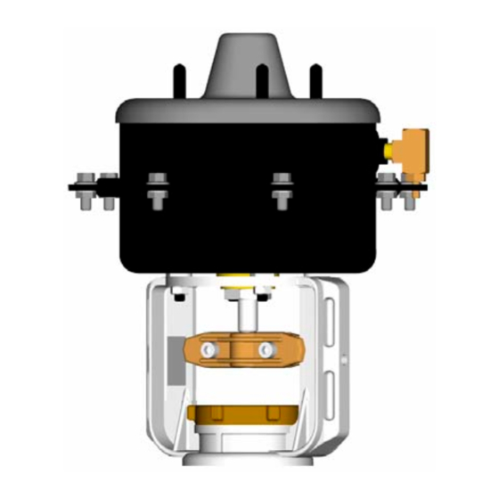
MP8xxxxx20 (MP8000)
Pneumatic Valve-Actuator
2
Stroke 13-mm
-4 to +80°C
160 kPa
3 – 2 – 3
SDI No.:
Issue date:
• Diaphragm material
• Housing material
• Stem material
111 6138 050 E
01/2003
EPDM
Ck 10 (1.1121)
9SMnPb36 (1.0737)
A
17
Advertisement

Related Manuals for Johnson Controls MP8 20 Series


Summary of Contents for Johnson Controls MP8 20 Series
- Page 1 SDI No.: 111 6138 050 E Issue date: 01/2003 MP8xxxxx20 (MP8000) Pneumatic Valve-Actuator General These service and data information (in brief SDI) are operating instructions and contain instructions for the safe installation and operation of the pneumatic actuator. Should difficulties occur, during installation, which cannot be solved with the help of this SDI please ask your supplier for further information.
- Page 2 111 6138 050 E Additional equipment • Hand wheel • Pneumatic positioner • (2) end position indicators + 2kΩ-feedback potentiometer Storage: • Storage temperature -4°C to +80°C, dry and free of dirt. • Do not damage the lacquer. The lacquer is a foundation intended only as a protection against corrosion while in storage and during transport.
-
Page 3: Pre-Installation Precautions
111 6138 050 E Danger: Safe operation of the valve is only ensured if the valve is installed, commissioned and serviced by qualified personnel in compliance with warning references in this SDI. In addition, the general installation and safety regulations for piping, installation construction and the professional use of tools and safety equipment must be guaranteed. - Page 4 111 6138 050 E Note: The pressure equipment directive (PED) and also the VDI/VDE 2174 from October 1967 for pneumatic actuators, have been observed Abbreviations: DA Actuator: Actuator stem extends (spring-return up). RA Actuator: Actuator stem retracts (spring-return down). Single item delivery DA and RA actuator construction details.
- Page 5 111 6138 050 E Fitting and removing DA hand wheel. Caution: It is necessary to grease the threaded bush (8) and threaded spindle (4). With the grease (in tube) provided. To fit carry out the following sequence 1. Remove cover. 2.
- Page 6 111 6138 050 E Hand wheel DA MP822 ( M = 10Nm )
- Page 7 111 6138 050 E Fitting and removing RA hand wheel. Caution: It is necessary to grease the threaded bush (2) and threaded spindle (3). With the grease (in tube) provided. To fit carry out the following sequence 1. Remove cover. 2.
- Page 8 111 6138 050 E Hand wheel RA MP832 ( M = 10Nm ) ( M = 40Nm )
- Page 9 111 6138 050 E To replace the hand-wheel gasket of a direct action device (DA): • Remove the hand-wheel assembly and cap. For refit see: Fitting and removing hand wheel. • Remove the circlip, then the nylon spacer and replace the gasket. Caution: The replacement gasket must be greased before use.
-
Page 10: Device Code
111 6138 050 E Removing the control valve (valve with actuator) Additional to the general installation guidelines and the TRB 700, the following points must be observed: • Pressure free pipe system • Sufficiently cooled fluid • Drained system • Sufficiently ventilated pipe system where aggressive and corrosive fluids are Danger concerned... - Page 11 Close-off Pressures [kPa] with VG Valves DA Actuator DA Actuator Spring-return up Air Pressure closes PDTO Valve PDTO Valve Mixing: Inlet 1 – Outlet Mixing: Inlet 1 – Outlet Diverting: Inlet – Outlet 2 (Bypass) Diverting: Inlet – Outlet 2 (Bypass) RA Actuator RA Actuator Spring-return down...
- Page 12 Close-off Pressures [kPa] with VBD Valves DA Actuator DA Actuator Spring-return up Air Pressure closes PDTO Valve PDTO Valve Mixing: Inlet 1 – Outlet Mixing: Inlet 1 – Outlet Diverting: Inlet – Outlet 2 (Bypass) Diverting: Inlet – Outlet 2 (Bypass) RA Actuator RA Actuator Spring-return down...
- Page 13 111 6138 050 E Dimensions in mm Approx. 38 Approx. 38 +0.15 +0.15 Ø54 Ø54 DA actuator without hand wheel DA actuator with hand wheel Approx. 38 Approx. 38 Ø54 +0.15 Ø54 +0.15 RA actuator without hand wheel RA actuator with hand wheel...
-
Page 14: Troubleshooting
111 6138 010 Causes and remedies when malfunction occurs When experiencing malfunction please check that the installation and adjustments were carried out in accordance with these operating instructions. Properly qualified personnel (see: Qualified personnel) must always be present during maintenance or repair. The TRB 700 is to be observed. Compare information regarding materials, pressure, temperature, flow direction, actuator action, spring range and controller, with installation plans of the piping system.