Advertisement
Proportional Digital Control Signal Input and
Applications
©
1993 Johnson Controls, Inc.
Part No. 34-636-70
Rev—
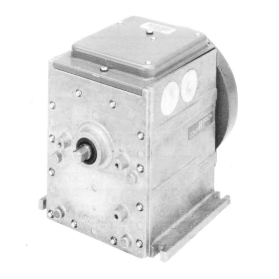
M100C Series of Motor Actuators with
R81C Interface Board
The M100C Series Motor Actuator is used in damper and valve
applications where proportional control from a digital controller is
required.
The M100C has the capability of communicating with Metasys ®
AHU/UNT or DSC1000 controllers depending on the position of the 8-pin
DIP switch. Other functions that are user programmable include master or
slave configuration, direct or reverse acting mode, the address to which the
actuator will respond and the linear or S-curve response characteristic.
Installation Sheets Manual 121
Motor Actuators Section M
Figure 1: M100
Technical Bulletin M100C
Issue Date 0493
1
Advertisement
Table of Contents

Related Manuals for Johnson Controls M100C Series


Summary of Contents for Johnson Controls M100C Series
- Page 1 Proportional Digital Control Signal Input and R81C Interface Board Applications Figure 1: M100 The M100C Series Motor Actuator is used in damper and valve applications where proportional control from a digital controller is required. The M100C has the capability of communicating with Metasys ®...
- Page 2 The M100C Motor Actuator travel is factory set at 90 degrees and is field Travel and Timing adjustable from 65 to 270 degrees. The timing of the actuator is 38 seconds for 90 degree rotation and 60 seconds for 160 degree rotation. 2 M Motor Actuators—M100C Series of Motor Actuators...
-
Page 3: Direction Of Rotation
Figure 3 shows the dimensions for a standard M100 Series Motor Actuator. Additional space is to be allowed for options such as a switch kit (two inches additional length at auxiliary end). M Motor Actuators—M100C Series of Motor Actuators 3... - Page 4 4 M Motor Actuators—M100C Series of Motor Actuators...
-
Page 5: Installation Procedures
When not utilizing a damper or valve linkage kit, use four 1/4 x 1 inch bolts for mounting the motor actuator. Perform travel adjustments described in the Travel Adjustment section as required. M Motor Actuators—M100C Series of Motor Actuators 5... - Page 6 1. Install terminal board by carefully placing the terminal receptacles onto the pin terminals. Terminal Board Screws Term ina l B o a rd Receptacles Pin Terminals M100C01 Figure 4: Terminal Receptacles 6 M Motor Actuators—M100C Series of Motor Actuators...
- Page 7 3. Install the vertical board (includes ribbon cable attached to the cover mounted board) by carefully placing the terminal receptacles onto the pin terminals as shown in Figure 5. Note: Align all pins within the receptacle. Bracket M100C03 Figure 6: Installing Bracket M Motor Actuators—M100C Series of Motor Actuators 7...
- Page 8 8. Make control and 24 VAC wiring connections as shown in the Control Wiring section. 9. Turn on power supply. 10. Cycle the motor actuator using the Y199 tester or controller to check operation. 8 M Motor Actuators—M100C Series of Motor Actuators...
- Page 9 AWG gauge, Beldfoil 8761 or equivalent for runs up to 250 feet (76 m). For 250 feet (76 m) to 500 feet (152 m) runs, use 18 AWG gauge Beldfoil 8760 or equivalent. M Motor Actuators—M100C Series of Motor Actuators 9...
- Page 10 Figure 10: Typical Parallel Wiring Diagram All Master Actuators Figure 10 shows a typical wiring diagram for a parallel system with all motor actuators set as master. Each motor actuator has a separate address. 10 M Motor Actuators—M100C Series of Motor Actuators...
- Page 11 Note: To avoid potential miswiring and electrical problems, the use of separate transformers for each M100 is required. Note: For further information on any of the controllers illustrated, reference the applicable controller literature. M Motor Actuators—M100C Series of Motor Actuators 11...
- Page 12 12 M Motor Actuators—M100C Series of Motor Actuators...
-
Page 13: Calibration Procedures
Address Selection* Address Selection* Address Selection* Address Selection* *Refer to Master/Slave section (page 14) for complete address selection options. CAUTION: Disconnect the electrical power supply before attempting to adjust the switch settings. M Motor Actuators—M100C Series of Motor Actuators 13... - Page 14 20% of command, increases during the mid 60% of command, and then decreases during the final 20% of the command. 100% 100% 100% 100% C ontrolle r C om m and C ontroller C om m and m100C09 Figure 13: Linear Characteristics 14 M Motor Actuators—M100C Series of Motor Actuators...
- Page 15 Configure multiple actuators with a separate address when each one performs a different function. When they all perform the same function, set one unit as the master, with the remaining units on that address set as slaves. M Motor Actuators—M100C Series of Motor Actuators 15...
-
Page 16: Off Value
+10 because of L1 Bus selection). Using the switches, any L1 address from 10 to 27 is selectable with the exception of Addresses 18 and 19 that are not available. 16 M Motor Actuators—M100C Series of Motor Actuators... -
Page 17: Operation
HVAC PRO service device (laptop PC). Do not connect any other device at the phone jack. Connection of another device at the phone jack may result in damage to the equipment or wiring. M Motor Actuators—M100C Series of Motor Actuators 17... - Page 18 The controller sends position commands to the actuator ranging from 0 to 100%. The actuator responds to these commands only over its selected range of travel. 100% (CW) Reverse Action Direct Action (CCW) 100% Controller Command M100C13 18 M Motor Actuators—M100C Series of Motor Actuators...
- Page 19 6. Remove the jumper from terminals COM and CW to allow the motor to return to the full CCW position. 7. Repeat Steps 4 through 6 to provide proper stroking. 8. Make sure that the power is off, and connect the control wires. M Motor Actuators—M100C Series of Motor Actuators 19...
-
Page 20: Troubleshooting Procedures
For repair parts or replacement, contact the nearest Johnson Controls Commercial Systems wholesaler or Systems and Services Division branch office. Controls Group FAN 121 507 E. Michigan Street Installation Sheets Manual P.O. Box 423 Printed in U.S.A. Milwaukee, WI 53201 20 M Motor Actuators—M100C Series of Motor Actuators...