Advertisement
Quick Links
The M100G Series Motor Actuator is used in
applications where dampers or valves are to be
modulated open or closed. Typical applications
include:
positioning of D-1300 Series Dampers
opening and closing a diverting valve
positioning a hot water, chilled water, or steam
valve
controlling an inlet vane damper on a fan
outdoor air, return air, and exhaust dampers
face and bypass control
blade positioning for variable volume fans
Refer to damper manufacturer's information to properly
size the damper and actuator. Return to normal
actuators are recommended for use with outdoor air
dampers.
Output Versatility
Load Versatility
Travel Adjustment Located in
Top Wiring Compartment
R81 Plug-in Electronic
Interface Boards
© 1994 Johnson Controls, Inc.
Part No. 34-636-100, Rev. A
M100G Proportional Motor Actuators
with DC/mA Control Signal Input
R81GAA-2 Interface Board
Features and Benefits
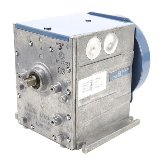
Figure 1: M100 Series Motor Actuator
Both ends of output shaft can be used for linkage
connections for dampers and full power in both
directions
Available in torques of 25, 35, 50, 75, and
150 in·lbs (2.8, 4.0, 5.7, 8.5, and 17 N·m)
Easy field screwdriver adjustment, reduces
installation time
Faster replacement or conversions and when
necessary, shorter service times, reduces
inventory
FANs 121, 1628.3
Product/Technical Bulletin M100G
Issue Date 0394
1
Advertisement

Related Manuals for Johnson Controls M100G


Summary of Contents for Johnson Controls M100G
- Page 1 Issue Date 0394 M100G Proportional Motor Actuators with DC/mA Control Signal Input R81GAA-2 Interface Board The M100G Series Motor Actuator is used in applications where dampers or valves are to be modulated open or closed. Typical applications include: positioning of D-1300 Series Dampers...
-
Page 2: Operation
Use the jumper selectable, direct and reverse acting The following table lists the torque rating for each M100G Series Motor Actuators with R81GAA-2 circuit model (MXXXGYZ-2--X = Model No.): boards in damper and valve applications for Table 1: Torque Rating proportional 0 to 10 VDC or 4 to 20 mA direct or reverse acting control signals. - Page 3 Timing irection of Rotation The M100G Motor Actuator travel is factory set at Direction of Drive Rotation Terminal 8 to 9 Shorted 90 degrees and is adjustable from 65 to 270 degrees. The timing of the actuator is 38 seconds for 90 degree 10°...
-
Page 4: Installation
Follow NEC and local electrical codes. shaft is parallel to the floor. Disconnect all power supplies. Observe the following ranges and limitations: 4 M100G Product/Technical Bulletin... - Page 5 6. Remove the terminal board by grasping the terminals as shown in Figure 6. receptacles and lifting straight upward being careful not to bend or damage the pin terminals. Note: Properly align all pins within the receptacle. Installing Boards To install the circuit boards: M100G Product/Technical Bulletin...
- Page 6 Series M100 with supply highly inductive loads (contactors, coils, motors, the R81 installed. generators, etc.). 6. Install the motor actuator. 7. Make control and 24 VAC wiring connections. 8. Turn on power supply. 9. Adjust, and check operation. 6 M100G Product/Technical Bulletin...
- Page 7 8 10 X Figure 12 shows an A350P powered by an external Figure 10: Typical Single Unit Wiring Diagram transformer driving an M100G Motor Actuator with DC voltage input. Note that the factory installed Note: The factory installed resistor is for a mA resistor has been removed.
- Page 8 Transformer 8 10 X Span 8 10 X Actuator One Figure 14: Wiring To TC-6100 +DC Input Figure 14 shows an M100G wired to a TC-6100 Power Cybertronic Temperature Controller. Connections one Supply R81GAA-2 and thirteen are used. Transformer To connect the wires: 8 10 X 1.
-
Page 9: Commissioning Procedures
The input impedance of the M100G Motor Actuators is Commissioning Procedures 44,000 ohms. Checkout Procedure Zero and Span After installation and wiring are complete, make The “Zero” (0.25 minimum, 24 VDC maximum) and system settings and apply power. After assembling “Span”... - Page 10 C W t r a v e l l i m i t . 13. Leave the span adjustment set at this point. Reverse Acting Mode Calibration 10 M100G Product/Technical Bulletin...
- Page 11 2. Be sure the actuator model selected has a range that covers the controller voltages desired. 3. By adjusting the controller setpoint up and down, the resulting voltage changes received by the motor actuators should result in proportional M100G Product/Technical Bulletin...
- Page 12 The performance specifications are nominal and conform to acceptable industry standards. For application at conditions beyond these specifications, consult the local Johnson Controls office. Johnson Controls, Inc. shall not be liable for damages resulting from misapplication or misuse of its products.