Table of Contents
Advertisement
Quick Links
Advertisement
Table of Contents

Related Manuals for Crestron Multimedia Presentation System 250 MPS-250


Summary of Contents for Crestron Multimedia Presentation System 250 MPS-250
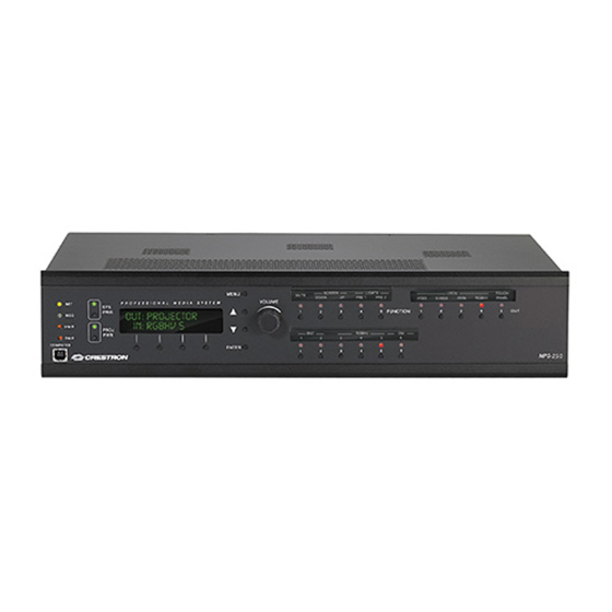
- Page 1 Crestron MPS-250 Multimedia Presentation System 250 Operations Guide...
-
Page 2: Important Safety Instructions
Important Safety Instructions • Read these instructions. • Keep these instructions. • Heed all warnings. • Follow all instructions. • Do not use this apparatus near water. • Clean only with dry cloth. • Do not block any ventilation openings. Install in accordance with the manufacturer’s instructions. -
Page 3: Table Of Contents
Crestron MPS-250 Contents Multimedia Presentation System 250: MPS-250 Introduction ... 1 Features and Functions ... 1 Applications... 4 Internal Block Diagram ... 5 Specifications ... 6 Physical Description... 10 Industry Compliance ... 21 Setup ... 22 Network Wiring... 22 CAT5 Wiring... 22 QuickMedia Wiring... -
Page 5: Multimedia Presentation System 250: Mps-250
Crestron MPS-250 Multimedia Presentation Multimedia Presentation System 250: MPS-250 System 250: MPS-250 Introduction Introduction The MPS-250 is a complete presentation control and signal routing solution for boardrooms and classrooms. Integrating the control system, multimedia matrix switcher, mic mixer, audio processor, amplifier, and QuickMedia all into a single 2-space rackmount package, the MPS-250 affords considerable signal routing versatility and high-performance signal processing without the need for separate components. - Page 6 Multimedia Presentation System 250 System Switcher Right out of the box, the MPS-250 provides high-performance switching of two video and three RGB computer sources to a single projector or plasma display. Composite, S-video, component and RGBHV signals can be routed to the appropriate inputs on the display device, with control of the display provided via Ethernet, RS-232 or IR.
-
Page 7: Front Panel Control
Crestron MPS-250 Professional Audio Features Five stereo audio inputs on the rear panel accept balanced or unbalanced line-level signals from computers and other program audio sources. Additional audio sources can be brought in through the QM input. To accommodate a wide range of signals, adjustable input compensation is employed to help maintain consistent volume levels when switching between sources. -
Page 8: Applications
Multimedia Presentation System 250 custom touchpanel based system with multiple controlled sources and display devices, can be programmed easily using Crestron SystemBuilder™ software. And, the MPS-250 works with Crestron's RoomView most comprehensive facility-wide asset management solution. Room Control Options Without requiring any programming, the MPS-250 can be controlled simply using Crestron’s APAD LCD Controller or a selection of keypads. -
Page 9: Internal Block Diagram
Operations Guide – DOC. 6647A Multimedia Presentation System 250 Composite S-Video Component Composite S-Video Component Matrix Switch RGBHV OUT 4 Analog Video to Multimedia Presentation System 250: MPS-250 • 5 VIDEO OUTPUTS LOCAL OUT 1 (1) Composite & (1) S-Video... -
Page 10: Specifications
Multimedia Presentation System 250 Audio Block Diagram of the MPS-250 AUDIO INPUTS COMP Stereo Audio COMP Stereo Audio COMP Stereo Audio Analog Matrix Switch COMP Stereo Audio Stereo Audio COMP QM IN Program/Mic Splitter Mic 1&2 Local Mic Gating With Phantom Power... - Page 11 Crestron MPS-250 MPS-250 Specifications (Continued) (Continued on following page) Operations Guide – DOC. 6647A Multimedia Presentation System 250 SPECIFICATION Video/RGB Switcher Signal Types Video/HDTV Formats RGB Formats Maximum Resolution Blanking Time Sync Rise/Fall Time Sync Latency Gain QM Cable Compensation Audio Switcher/Preamp A-D/D-A Conversion...
- Page 12 Multimedia Presentation System 250 MPS-250 Specifications (Continued) (Continued on following page) 8 • Multimedia Presentation System 250: MPS-250 SPECIFICATION Audio (continued) Limiter Curve Limiter Threshold Level Limiter Attack Time Limiter Release Time Microphone EQ Filter Gain Mic EQ Filter Center Frequencies Bass Gain Range Treble Gain Range...
- Page 13 Crestron MPS-250 MPS-250 Specifications (Continued) (Continued on following page) Operations Guide – DOC. 6647A Multimedia Presentation System 250 SPECIFICATION LCD Display Power Requirements Main Power ® Available Cresnet Power Environmental Temperature Humidity Heat Dissipation Enclosure Chassis Faceplate Mounting Dimensions Height Width Depth Weight:...
-
Page 14: Physical Description
Crestron MPS-250 DETAILS Wall Mount LCD Controller 12-Button Decorator Keypad FlipTop Control Center infiNET™ Gateway iLux™ Integrated Lighting System infiNET Dimmer and Switch Custom Serial Interface Cable 12-Button Designer Keypad IR Receiver IR Probe 3-Channel Multimedia Amplifier 3-Channel Sound Reinforcement Amplifier... - Page 15 Crestron MPS-250 Multimedia Presentation System 250 MPS-250 Overall Dimensions 12.58 in (31.95 cm) 11.85 in (30.08 cm) 17.03 in (43.24 cm) 3.47 in (8.81 cm) Multimedia Presentation System 250: MPS-250 • 11 Operations Guide – DOC. 6647A...
- Page 16 Multimedia Presentation System 250 MPS-250 Buttons and Ports 12 • Multimedia Presentation System 250: MPS-250 18 21 Crestron MPS-250 Operations Guide – DOC. 6647A...
- Page 17 Crestron MPS-250 Connectors, Controls & Indicators (Continued on following page) Operations Guide – DOC. 6647A Multimedia Presentation System 250 CONNECTORS CONTROLS & INDICATORS NET LED MSG LED 3 & 4 RESET BUTTONS COMPUTER Pin 4 Pin 3 Pin 1 Pin 2 PROGRAM OUT (L/R) (1) 5-pin 3.5 mm detachable terminal block;...
- Page 18 RGB Input Impedance: 75 ohms nominal; Sync Input Level: 2 to 5 V Sync Input Impedance: 75, 500, or 1k ohms individually selectable for H and V via bottom panel DIP switch; Video signal sensing on “H-SYNC”; Defeatable DDC pull-up resistors SYSTEM POWER...
- Page 19 Crestron MPS-250 Connectors, Controls, & Indicators (Continued) (Continued on following page) Operations Guide – DOC. 6647A Multimedia Presentation System 250 CONNECTORS CONTROLS & INDICATORS REC OUT (1) 5-pin 3.5 mm detachable terminal block; Balanced/unbalanced, stereo line-level output; Output Impedance: 200 ohms balanced, 100 ohms unbalanced;...
- Page 20 Multimedia Presentation System 250 Connectors, Controls, & Indicators (Continued) (Continued on following page) 16 • Multimedia Presentation System 250: MPS-250 CONNECTORS CONTROLS & INDICATORS IR/SERIAL OUT (4) 2-pin 3.5 mm detachable terminal blocks, IR/Serial output ports; IR output up to 1.2 MHz;...
- Page 21 Crestron MPS-250 Connectors, Controls, & Indicators (Continued) (Continued on following page) Operations Guide – DOC. 6647A Multimedia Presentation System 250 CONNECTORS CONTROLS & INDICATORS TOUCH PANEL OUT Contains one CH port and one QM port. CH Port: 8-wire RJ-45 female; CAT5 balanced video output port;...
- Page 22 Multimedia Presentation System 250 Connectors, Controls, & Indicators (Continued) (Continued on following page) 18 • Multimedia Presentation System 250: MPS-250 CONNECTORS CONTROLS & INDICATORS COM A & B (2) DB9 male, bidirectional RS-232 ports; Up to 115.2k baud, hardware and software handshaking support for communication with serial devices.
- Page 23 Crestron MPS-250 Connectors, Controls, & Indicators (Continued) (Continued on following page) Operations Guide – DOC. 6647A Multimedia Presentation System 250 CONNECTORS CONTROLS & INDICATORS OUTPUT 1-4 Contains composite, S-video (Y/C), component (Y, P six BNC connectors and one DB15HD connector. Composite/P (1) BNC female, composite video output, or output;...
- Page 24 Multimedia Presentation System 250 Connectors, Controls, & Indicators (Continued) 20 • Multimedia Presentation System 250: MPS-250 CONNECTORS CONTROLS & INDICATORS 100 – 240V ~2.5A (1) IEC Socket, mates with removable power 50/60 Hz cord (included). (POWER SUPPLY) Interface connectors for NET, INFRARED-SERIAL, IR IN, INPUT, RELAY OUTPUT, and AUDIO ports are provided with the unit.
-
Page 25: Industry Compliance
Crestron MPS-250 Industry Compliance This unit has been manufactured to comply with UL’s Standards for Safety in Canada and the United States. Formal approval is pending. As of the date of manufacture, the MPS-250 has been tested and found to comply with specifications for CE marking and standards per EMC and Radiocommunications Compliance Labelling. -
Page 26: Setup
Multimedia Presentation System 250 Setup Network Wiring When wiring the Cresnet For networks with 20 or more devices, use a Cresnet Hub/Repeater (CNXHUB) to Cresnet maintain signal quality. For more details, refer to “Check Network Wiring” on page 85. The MPS-250 can also use high-speed Ethernet for communications between the Ethernet control system and a device, computer, digital media server and other IP-based devices... - Page 27 Crestron MPS-250 CresCAT-QM Cable NOTE: Do not untwist the two wires in a single pair for more than 1/3-1/2” (0.84-1.27 cm) when making a connection. The twists are critical to canceling out interference between the wires. The aggregate cable length of a signal path originating at the MPS-250 and terminating at a QM receiver must not exceed 450 feet (137 meters).
-
Page 28: Installation
Multimedia Presentation System 250 QM Network Topology Origination Points MPS-250 MPS-250 Installation The MPS-250 should be used in a well-ventilated area. The venting holes should not Ventilation be obstructed under any circumstances. To prevent overheating, do not operate this product in an area that exceeds the environmental temperature range listed in the table of specifications. -
Page 29: Hardware Hookup
Crestron MPS-250 NOTE: The sync input impedance and DDC feature should be set prior to placing the MPS-250 in an equipment rack. For more information, refer to “Configure the RGB Input Ports” on page 28. Four “feet” are provided with the MPS-250 so that if the unit is not rack mounted, Stacking the rubber feet can provide stability when the unit is placed on a flat surface or stacked. - Page 30 Multimedia Presentation System 250 Hardware Connections for the MPS-250, Front Hardware Connections for the MPS-250, Rear When running the out-of-the-box program, the MPS-250 can support the following Crestron devices: CAUTION: Speakers must be rated to full available output. CAUTION: Do not bridge speaker outputs 26 •...
- Page 31 Crestron MPS-250 CAUTION: All source devices should be grounded to the MPS-250. NOTE: The MPS-250 can only be powered by the included power cord. Power cannot be supplied from network devices that are connected to the mini-terminal block connectors. NOTE: For Cresnet, CAT5, and QuickMedia connections, use Crestron Certified Wire.
-
Page 32: Configure The Rgb Input Ports
RGB sources (such as a laptop computer) will transmit a signal even when an RGB device is not connected to the MPS-250 output. Changing the DIP switch setting can enable or disable this feature. The MPS-250 is shipped from the factory with the DDC feature disabled. - Page 33 Crestron MPS-250 DIP Switch Location Set the DIP Switches DIP Switch Function Chart If using the out-of-the-box functionality, the MPS-250 can be configured with the Further Configuration front panel. For information, refer to “Configuration” on page 36. Operations Guide – DOC. 6647A...
- Page 34 Multimedia Presentation System 250 Use Crestron Engraver software to print custom labels for the MPS-250’s front panel Label the Buttons buttons and LEDS. Crestron recommends printing on 100-pound paper. Paper weighing less than 100 pounds will tend to crumple while sliding in, while paper weighing more than 100 pounds may not fit.
-
Page 35: Programming Software
Crestron MPS-250 Programming Software Have a question or comment about Crestron software? Answers to frequently asked questions (FAQs) can be viewed in the Online Help section of the Crestron website. To post a question or view questions you have submitted to Crestron’s True Blue Support, log in at http://support.crestron.com. First-time users will need to establish a user account. -
Page 36: Switching Programs
Switching Programs If a custom program is loaded into the MPS-250, the MPS-250 will run the custom program when it boots up. To switch to the out-of-the-box program: Saving Settings Settings such as tone/volume levels (out-of-the-box and custom programs) and input/output names (out-of-the-box programs) are stored in an xml and text file that can be recalled should an MPS-250 program need to be updated. - Page 37 Crestron MPS-250 of-the-box functionality program or “custom” for settings made when running a custom program) and System Configuration.txt files from the NVRAM Disk directory. After the new out-of-the-box functionality program or custom program has been loaded, use Windows Explorer and Crestron Toolbox File Manager utility to place the appropriate *.xml and System Configuration.txt files in the NVRAM Disk directory and reboot the processor.
-
Page 38: Uploading And Upgrading
Multimedia Presentation System 250 Uploading and Upgrading Crestron recommends using the latest programming software and that each device contains the latest firmware to take advantage of the most recently released features. However, before attempting to upload or upgrade it is necessary to establish communication. -
Page 39: Programs And Firmware
Crestron MPS-250 TCP/IP Ethernet Communication Programs and Firmware Program or firmware files may be distributed from programmers to installers or from Crestron to dealers. Firmware upgrades are available from the Crestron website as new features are developed after product releases. One has the option to upload programs via the programming software or to upload and upgrade via the Crestron Toolbox. -
Page 40: Configuration & Operation
Multimedia Presentation System 250 Configuration & Operation The MPS-250 can be used for audio and video switching without any programming required. This is ideal for those that need a basic audio-video switching system. Prior to operation, the MPS-250 must be configured for use. Configuration The MPS-250 is configured using the built-in menu. - Page 41 Crestron MPS-250 To exit the menu: Exit the Menu NOTE: The following sections describe configuration instructions when the MPS-250 is running the out-of-the-box program or if an administrator password was entered (while a custom program is running). If a user password was entered while a custom program is running, the user can view the settings but cannot make changes.
-
Page 42: Audio Setup
Multimedia Presentation System 250 The menu is separated into four sections. Audio Setup The audio characteristics of the MPS-250 can be configured from the front panel using the Audio Setup menu. To access the Audio Setup menu: Access the Audio Setup Menu Program Output The Program Output section of the Audio Setup menu is used to set the... - Page 43 Crestron MPS-250 To set the Program Bass level: Set the Program Bass Level Operations Guide – DOC. 6647A Multimedia Presentation System 250 • Press the k or j buttons until “Source Mix” is displayed on the LCD and press ENTER to open the Program Source Mix controls. Program Source Mix Controls Program Source Mix Aud.
- Page 44 Multimedia Presentation System 250 To set the Program Treble level: Set the Program Treble Level The Program Minimum Volume control is used to set the lowest volume setting of Set the Program Minimum the PROGRAM output. The RECORD and SPEECH outputs are not affected by Volume changes made to the Program Minimum Volume level.
- Page 45 Crestron MPS-250 The Program Maximum Volume control is used to set the highest volume setting of Set the Program Maximum the PROGRAM output. The RECORD and SPEECH outputs are not affected by Volume changes made to the Program Maximum Volume level. To set the Program Maximum Volume level: Operations Guide –...
- Page 46 Multimedia Presentation System 250 The Stereo / Mono controls are used to set the PROGRAM output mode. The audio Set the Stereo / Mono Mode sent to the speaker outputs can be set for either stereo or mono. When set to stereo, the audio signal is separated into left and right channels for distribution to left and right speakers or amplifier channels.
- Page 47 Crestron MPS-250 Speech Output The Speech Output section of the Audio Setup menu is used to set the SPEECH output’s volume level, source mix, bass, treble, speech delay, minimum volume, maximum volume, and startup volume. The PROGRAM and RECORD outputs are not affected by changes made from the Speech Output menu.
- Page 48 Multimedia Presentation System 250 To set the Speech Bass level: Set the Speech Bass Level 44 • Multimedia Presentation System 250: MPS-250 Speech Source Mix Controls Speech Source Mix Aud. Only • Press the k or j buttons until the desired setting is displayed on the LCD. The current setting is indicated with an asterisk (*).
- Page 49 Crestron MPS-250 To set the Speech Treble level: Set the Speech Treble Level To set the Speech Delay: Set the Speech Delay Operations Guide – DOC. 6647A Multimedia Presentation System 250 NOTE: While adjusting the Speech Bass level, the Speech Volume level can be adjusted by turning the volume control clockwise to raise the volume, or counterclockwise to lower the volume.
- Page 50 Multimedia Presentation System 250 The operating mode of the volume control knob can be set to adjust the program Change the Volume Control volume, the speech volume, user-selectable program/speech volume, or the master Mode volume. To change the Volume Control Mode: 46 •...
- Page 51 Crestron MPS-250 The MPS-250 ships with the Volume Control Mode set to the Master Vol. setting. When switching the Volume Control Mode from the Master Vol. setting to either the Program Only setting, the Speech Only setting, or the user selectable Pgm/Spch Sel.
- Page 52 Multimedia Presentation System 250 The Speech Maximum Volume control is used to set the highest volume setting of Set the Speech Maximum the SPEECH output. The RECORD and PROGRAM outputs are not affected by Volume changes made to the Speech Maximum Volume level. To set the Speech Maximum Volume level: 48 •...
- Page 53 Crestron MPS-250 The Speech Startup Volume control is used to establish the SPEECH output’s Adjust the Speech Startup volume level setting when an input is selected. The RECORD and PROGRAM Volume outputs are not affected by changes made to the Speech Startup Volume level. To adjust the Speech Startup Volume level: Record Output The Record Output section of the Audio Setup menu is used to set the RECORD...
- Page 54 Multimedia Presentation System 250 To set the RECORD output’s source mix: Set the Record Source Mix The RECORD output can be set to operate at a fixed level or a variable level. The Set Fixed/Variable Mode SPEECH and PROGRAM outputs are not affected by changes made to the Fixed/Variable mode.
- Page 55 Crestron MPS-250 The Record Startup Volume control is used to establish the RECORD output’s Adjust the Record Startup volume level setting when an input is selected. The SPEECH and PROGRAM Volume outputs are not affected by changes made to the Record Startup Volume level. NOTE: The Record Volume can only be used if the Fixed/Variable Mode is set to “Variable”.
- Page 56 Multimedia Presentation System 250 Input Compensation The compensation level of each input can be set from the MPS-250’s front panel. The line outputs are not affected by changes made to the input compensation level. To set the compensation level for an input: Set the Compensation Level 52 •...
- Page 57 Crestron MPS-250 Master Startup Volume Control The Master Startup Volume control is used to establish the volume level setting when an input is selected. The RECORD output is not affected by changes made to the Master Startup Volume level. To adjust the Master Startup Volume control: Adjust the Master Startup Volume Microphones...
- Page 58 Multimedia Presentation System 250 Microphone gating can be individually set on each microphone input. To switch Switch Microphone Gating microphone gating on or off: Microphone compression can be individually set on each microphone input. To Switch Microphone switch microphone compression on or off: Compression 54 •...
-
Page 59: Phantom Power
A microphone limiter can be individually set on each microphone input. To switch Switch Microphone Limiter the microphone limiter on or off: Phantom power for the microphone inputs can be switched on or off. To switch Switch Phantom Power phantom power on or off: Operations Guide –... - Page 60 Multimedia Presentation System 250 The gain for each microphone input can be individually set. To adjust the gain of a Adjust Microphone Gain microphone input: Video Setup The video characteristics of the MPS-250 can be configured from the front panel using the Video Setup menu.
- Page 61 Crestron MPS-250 The BNC video inputs of the MPS-250 can accept composite, S-video, or component Select Input Type signals. The RGB inputs of the MPS-250 can accept component or RGBHV signals. The QM inputs of the MPS-250 can accept composite, S-video, component, or RGBHV signals.
- Page 62 Multimedia Presentation System 250 The MPS-250 ships with default names assigned to each of the outputs. Output 1 is Name Video Outputs called “Output 1”. Output 2 is called “Output 2”. Output 3 is called “Output 3”. Output 4 is called “Output 4”. Output 5 is called “QM Output 5”. To change the output names: 58 •...
-
Page 63: Network Setup
Crestron MPS-250 Network Setup The network settings of the MPS-250 can be configured and reviewed from the front panel using the Network Setup menu. NOTE: Some changes to network settings may require a reboot to take effect. The system will automatically reboot when necessary. To access the Network Setup menu: Access the Network Setup Menu... -
Page 64: Subnet Mask
Multimedia Presentation System 250 The MPS-250 can be configured to use an IP Subnet Mask for TCP/IP Set the Subnet Mask communications. To set the address of the IP Subnet Mask: 60 • Multimedia Presentation System 250: MPS-250 Display the IP Address IP Address [000] 000. - Page 65 Crestron MPS-250 The MPS-250 can be configured to use a Default Router for TCP/IP Set the Default Router communications. To set the IP address of the Default Router: The IP address can be obtained from a DHCP server or manually set. For Set the DHCP Mode information on manually setting the IP address, refer to “Set the IP Address”...
- Page 66 Multimedia Presentation System 250 The MPS-250 can use a WINS server to obtain an IP address. To set the WINS Set the WINS Mode mode: The MPS-250 can be recognized by its hostname in a networked environment. To View and Set the Hostname view and set the hostname: 62 •...
-
Page 67: Domain Name
Crestron MPS-250 Some networks may require a Domain name to resolve the hostname. To view and View and Set the Domain set the Domain name: Name Operations Guide – DOC. 6647A Multimedia Presentation System 250 Change the Hostname MPS-250-00107EA0122_ • Turn the volume control clockwise or counterclockwise (or press the k or j buttons) to select a new letter (uppercase or lowercase) or number. - Page 68 Multimedia Presentation System 250 The MPS-250 can be configured to report to RoomView Express (formerly known as Set the RoomView Mode RoomView 6.0) or RoomView Server Edition (formerly known as RoomView 7.0). To set the version of RoomView: For more information on using RoomView, refer to the RoomView help file. The MPS-250 can display its MAC address.
- Page 69 Crestron MPS-250 Control Setup Basic control system operations can be performed from the MPS-250 front panel using the Control Setup menu. To access the Control Setup menu: Access the Control Setup Menu The brightness of the LCD’s backlight can be adjusted for ease of viewing. To adjust Change the Backlight Level the brightness level from the front panel: The MPS-250 ships with default names assigned to each of the five function buttons.
- Page 70 Multimedia Presentation System 250 Use the front panel to identify the presence of Cresnet devices such as APAD, Identify Network Devices C2N-DB12, CNX-B12, and C2N-FTB keypads, C2N-MNETGW gateways, CLS-C6 lighting systems, and QM-AMP amplifiers: 66 • Multimedia Presentation System 250: MPS-250 Select Function to Name Select Fct.
-
Page 71: All Devices
NOTE: If a C2N-MNETGW has been identified, infiNET switches and dimmers must still be identified with Crestron Toolbox. Refer to the respective infiNET switch and dimmer manuals for more information. APAD devices may need to be programmed to work with the MPS-250. If a Upgrade Connected APADs connected APAD does not display controls for the MPS-250, perform the following. - Page 72 Multimedia Presentation System 250 The front panel password can be changed from the front panel: Change the Front Panel Password Use the front panel to view information about the MPS-250. Information that can be View System Information viewed includes program information, hardware information, network information, and operating system information.
- Page 73 Crestron MPS-250 Operations Guide – DOC. 6647A Multimedia Presentation System 250 • Press the k or j buttons until “Info” is displayed on the LCD and press ENTER to display the Info menu. Display the Info Menu Info REMS • To view program information, press the soft button labeled REMS.
- Page 74 Multimedia Presentation System 250 The MPS-250 stores system messages in a message log. The presence of new Review System Messages messages in the log is indicated when the MSG LED is lit. To review system messages using the front panel: 70 •...
-
Page 75: System Log
Crestron MPS-250 NOTE: The contents of the message log can be read and saved using Crestron Toolbox. For more information, refer to the Crestron Toolbox help file. Use the front panel to set the MPS-250’s date and time. Set the Date and Time Operations Guide –... - Page 76 Multimedia Presentation System 250 NOTE: The date and time can be set using Crestron Toolbox. For more information, refer to the Crestron Toolbox help file. 72 • Multimedia Presentation System 250: MPS-250 Display the Date Controls DATE: 10/16/2006 ⇒ To set the month, press the soft button labeled MO. To set the day, press the soft button labeled DAY.
-
Page 77: Restore Defaults
Crestron MPS-250 The MPS-250 can be restored to its default factory settings from the front panel. Restore Default Settings Users can select to restore the audio settings or to restore the audio settings, source names, output names, and function names. Operations Guide –... - Page 78 Multimedia Presentation System 250 The MPS-250’s front panel controls can be locked to prevent operational changes Front Panel Lock Control from the buttons on the front of the MPS-250. While locked, the menu can be accessed by pressing the MENU button. To open the Front Panel Lock control: 74 •...
-
Page 79: Operation
Crestron MPS-250 Operation Using the out-of-the-box functionality, the MPS-250 can be operated from the front panel, an APAD, a 12-button keypad such as the CNX-B12 or the C2N-DB12, or the C2N-FTB FlipTop Control Center. Control from the Front Panel The following describes operation of a system when using the out-of-the-box functionality and the front panel. - Page 80 Multimedia Presentation System 250 Press the button labeled SCREEN UP to raise the projector screen. Raise the Projection Screen NOTE: This function will only work if a projection screen’s control lines have been connected to RELAY 1 (up control) and RELAY 2 (down control). The volume control of the MPS-250 consists of three parts;...
- Page 81 Adjust Lighting LIGHTS PRE 2. NOTE: This function will only work if a CLS-C6, infiNET switch, or infiNET dimmer was previously identified and connected to the MPS-250. The CLS-C6 can be identified as a Cresnet device in the MPS-250 setup screens as described on page 66.
- Page 82 Multimedia Presentation System 250 To turn off the system: Turn Off the System To raise or lower the projection screen: Raise or Lower the Projection Screen NOTE: This function will only work if a projection screen’s control lines have been connected to RELAY 1 (up control) and RELAY 2 (down control).
- Page 83 Crestron MPS-250 NOTE: This function will only work if a CLS-C6, infiNET switch, or infiNET dimmer was previously identified and connected to the MPS-250. The CLS-C6 can be identified as a Cresnet device in the MPS-250 setup screens as described on page 66.
- Page 84 Multimedia Presentation System 250 When switching sources from the keypad, the MPS-250 will route the signal to the projector output and then route the signal to the touchpanel output. To turn on the system, press any of the source buttons on the button pad. The Turn On the System selected source will be routed to all of the outputs.
- Page 85 Adjust Lighting front panel of the MPS-250 will indicate the selected preset light setting. NOTE: This function will only work if a CLS-C6, infiNET switch, or infiNET dimmer was previously identified and connected to the MPS-250. The CLS-C6 can be identified as a Cresnet device in the MPS-250 setup screens as described on page 66.
-
Page 86: Problem Solving
Multimedia Presentation System 250 Problem Solving Troubleshooting The following table provides corrective action for possible trouble situations. If further assistance is required, please contact a Crestron customer service representative. MPS-250 Troubleshooting (Continued on following page) 82 • Multimedia Presentation System 250: MPS-250 TROUBLE POSSIBLE CAUSE(S) Unexpected... -
Page 87: System Monitor
Crestron MPS-250 MPS-250 Troubleshooting (Continued) NOTE: If communication cannot be established or the control system is locked-up, refer to “Troubleshooting Communications” in the Crestron 2-Series Control Systems Reference Guide (Doc. 6256). NOTE: Passthrough Mode enables Viewport access to any serial controlled device on the network. -
Page 88: Battery Replacement
Multimedia Presentation System 250 Network Analysis If Cresnet analysis is required, contact Crestron’s True Blue Support. Battery Replacement A Lithium battery is used to power the system clock within the MPS-250. Under normal conditions, it will last for approximately 10 years. In the event that the clock fails, only an authorized technician should replace it. -
Page 89: Check Network Wiring
Crestron MPS-250 Check Network Wiring In order to ensure optimum performance over the full range of your installation Use the Right Wire topology, Crestron Certified Wire and only Crestron Certified Wire may be used. Failure to do so may incur additional charges if support is required to identify performance deficiencies because of using improper wire. -
Page 90: Reference Documents
Multimedia Presentation System 250 Reference Documents The latest version of all documents mentioned within the guide can be obtained from the Crestron website (www.crestron.com/manuals). This link will provide a list of product manuals arranged in alphabetical order by model number. List of Related Reference Documents Further Inquiries If you cannot locate specific information or have questions after reviewing this... -
Page 91: Software License Agreement
Crestron MPS-250 Software License Agreement This License Agreement (“Agreement”) is a legal contract between you (either an individual or a single business entity) and Crestron Electronics, Inc. (“Crestron”) for software referenced in this guide, which includes computer software and as applicable, associated media, printed materials and “online”... - Page 92 Multimedia Presentation System 250 If You are a business or organization, You agree that upon request from Crestron or its authorized agent, You will within thirty (30) days fully document and certify that use of any and all Software at the time of the request is in conformity with Your valid licenses from Crestron of its authorized agent.
-
Page 93: Return And Warranty Policies
Crestron MPS-250 Return and Warranty Policies Merchandise Returns / Repair Service 1. No merchandise may be returned for credit, exchange or service without prior authorization from CRESTRON. To obtain warranty service for CRESTRON products, contact an authorized CRESTRON dealer. Only authorized CRESTRON dealers may contact the factory and request an RMA (Return Merchandise Authorization) number. - Page 94 Crestron Electronics, Inc. Operations Guide – DOC. 6647A 15 Volvo Drive Rockleigh, NJ 07647 (2019926) Tel: 888.CRESTRON 06.08 Fax: 201.767.7576 Specifications subject to www.crestron.com change without notice.