Shure AXT610 - ShowLink Access Point Manual
- User manual (7 pages) ,
- User manual (5 pages) ,
- Manual (13 pages)
Advertisement
Introduction
The AXT610 ShowLink access point enables real-time remote control of the Axient transmitters. The access point allows comprehensive management of transmitter parameters from the receiver or Wireless Workbench 6 using 2.4 GHz wireless network communication. All parameter changes occur without interruption to the performer.
Multiple access points can extend the operational range or increase the number of transmitters supported on the ShowLink network.
Features
- Real-time wireless remote control of up to 16 transmitters per ShowLink access point
- Automated channel selection - Independently scans 2.4 GHz frequency range and determines best channel for use
- Receives power via Power over Ethernet (PoE) network connection or from an external power supply
- Easy transmitter authentication - Recognizes linked transmitters upon IR sync
- Provides coverage area approximately the same as the transmitter's UHF range (depending on the RF squelch setting of the receiver)
- Automatic hand-offs between multiple access points extend coverage range
- Automatic frequency agility - Moves a ShowLink network to the best available 2.4 GHz channel in the event of signal degradation
- Versatile mounting options - Fits readily available microphone stand adapters and features built-in threading for permanent installation
- Wireless Workbench 6 system supports networked control of all device functions and provides a ShowLink plot for viewing 2.4 GHz signal levels
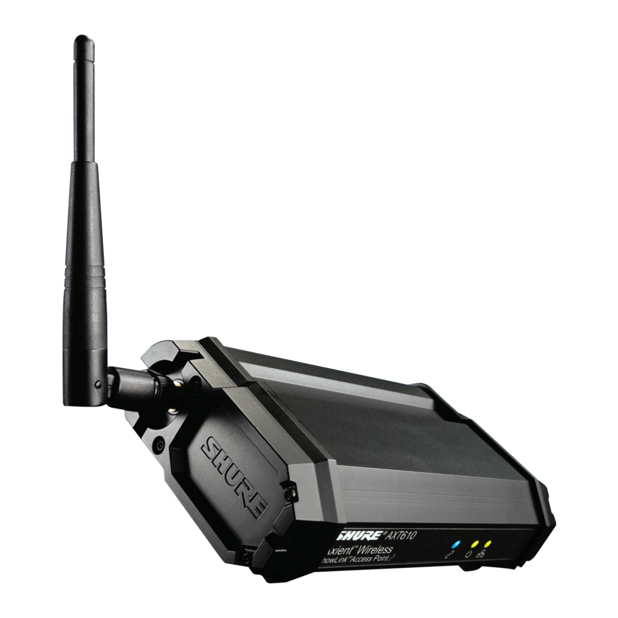
Device Overview

- ShowLink 2.4 GHz detachable antenna
For 2.4 GHz signals - ShowLink Data Status LED (blue)
- ON Steady: Linked, no data transmission
- Flashing: Transmitting data - rate of flashing indicates level of activity
- Power Status LED (green/amber/red)
- Steady Green: Power ON, power source = PoE
- Steady Amber: Power ON, power source = external power supply
- Red Flashing: Response to remote ID flash command
- Ethernet Status LED (green)
- ON Steady: Ethernet connected, no traffic
- ON Flashing: Ethernet connected, flashing corresponds to volume of data traffic
- Threaded mounting point
Use to wall mount the access point - External power supply connector
Connection point for external power supply - Reset button
Press to restore factory settings - Ethernet port
For network connection and Class 1 PoE - Scanning antenna for channel agility
Scans the 2.4 GHz spectrum for the best frequency
Included Components
| Wireless microphone clip for mounting on a microphone stand | WA371 |
| Euro thread adapter for WA371 | 31A1856 |
| Shielded 25-foot Ethernet cable for ShowLink access point, RJ45-to-EtherCon connector | C825 |
ShowLink Basics
ShowLink Channels and 2.4 GHz Spectrum
ShowLink channels that enable remote control of Axient transmitters operate in the 2.40 to 2.484 GHz portion of the RF spectrum in accordance with the IEEE 802.15.4 protocol. Devices that share the 2.4 GHZ spectrum, including Wi-Fi, are manufactured to efficiently share the spectrum and cause minimal interference. Both ShowLink and Wi-Fi use "listen before talk" technology to transmit short message packets only when needed to conserve bandwidth. Available spectrum, low interference, and global availability make the 2.4 GHz spectrum an ideal choice for hosting ShowLink channels.
Within the 2.4 GHz spectrum, 16 channels are available for ShowLink communication. To ensure reliable communication, the access point contains an internal scanning radio that analyzes the 2.4 GHz spectrum hundreds of times per second. If interference is detected, the access point uses channel agility to automatically switch to a clear channel within the spectrum. All transmitters associated with the access point will continue to communicate uninterrupted on the new ShowLink channel. If ShowLink goes off-line for any reason, audio transmission will not be interrupted.
Coverage Area
The coverage area of the access point is approximately the same as the transmitter's UHF range (depending on the RF squelch setting of the receiver). Use the ShowLink Test feature in the receiver menu to map the boundaries of the coverage area. Multiple access points can be used to increase the coverage area or to expand coverage to multiple rooms.
Transmitter Capacity
A single access point supports up to 16 Axient transmitters. Any transmitter within range of an active access point with available capacity will be automatically controlled by that access point. When multiple access points are used to increase transmitter capacity or to increase coverage range, transmitter control is automatically divided between each access point. All changes in control between access points occur seamlessly and automatically, without requiring user intervention.
Transmitter Control
An access point with available capacity will automatically control linked transmitters that are within the coverage area. Multiple access points automatically self-manage to divide transmitter control and maintain coverage. Transitions between access point control do not affect the transmission of the audio channel.
2.4 GHz Channel Agility to Avoid Interference
When interference is present from Wi-Fi or other devices sharing the spectrum, built-in channel agility automatically switches the access point and all controlled transmitters to a clear channel. Channel agility is able to avoid interference from the following devices that operate in the 2.4 GHz spectrum:
- Wi-Fi (802.11)
- Cordless phones
- Wireless video
ShowLink Icon
The ShowLink icon appears on the home screens of a linked transmitter and receiver to indicate that the transmitter is within range of an access point making remote control possible. If the transmitter is beyond the range of the access point, or if the receiver is off-line, the icon will disappear, indicating a loss of ShowLink control.
Power
The access point is powered through Power Over Ethernet (PoE) enabled network ports. If PoE is not available, an external power supply may be used.

Power Over Ethernet
The Shure Ethernet switch and Axient rack components offer network ports with Power over Ethernet (PoE). The network port powers the access point as long as the host component is powered on.
- Insert a CAT-5 Ethernet cable into the Ethernet port located on the body of the access point.
- The Ethernet PoE connection supplies power for the access point.
External Power Supply
Optional
If Power over Ethernet (PoE) is not available, power the access point using an external power source supplying 15 V DC ±10% (600 mA).
- Connect the power source to the external power supply jack.
- Tighten the locking ring to secure the plug.
- Plug the power supply AC line cord into an AC power source.
- Connect a CAT 5 Ethernet cable to the access point to provide a network connection.
Networking
Networking the access point using a Shure AXT620 Ethernet switch or a DHCP-enabled router automatically assigns an IP address, simplifying network setup. The network connection allows the access point to share data with networked components and enables wireless control of the transmitters. To manually assign an IP address to the access point, use Wireless Workbench 6.
Reset Option

Pressing the reset button located on the bottom of the housing restores the access point to the following settings:
- IP Address Mode = DHCP
- Channel Agility = Enabled
- Device ID = AXT610
- Device Association Tables will be cleared
Positioning the Device
- Provide a clear line of sight between the access point and transmitters: mount the access point on a microphone stand or wall to elevate above obstructions
![]()
- Position the antenna vertically for optimal performance. The swivel joint on the antenna allows a wide range of positioning to maintain a vertical alignment

Control and Configure the Unit with Wireless Workbench 6
Wireless Workbench 6 adds the following configuration and networking options for the access point:
- Edit Device ID
- View connected transmitters
- View transmitter capacity
- Disable channel agility for troubleshooting
- Set IP Address Mode: DHCP or Manual
- Set IP Address: Edit in Manual Address Mode
- View and set subnet mask
- View MAC address
Tip: The text color of the Device ID for each transmitter in the Connected list indicates Link Quality:
- Green = Excellent
- Yellow = Good
- Red = Marginal
Hovering the cursor over the Device ID displays Link Quality ranked from 5 to 1.
Specifications
Antenna Type
Omnidirectional 2.4 GHz
Capacity
16 Axient transmitters
Mounting Type
WA371 Mic Clip or 1/4-20 thread mount
Operating Temperature Range
-18°C (0°F) to 63°C (145°F)
Storage Temperature Range
-29°C (-20°F) to 74°C (165°F)
Dimensions
186 mm x 101 mm x 46 mm (7.34 in. x 3.960 in. x 1.825 in.) H x W x D, without antenna
Weight
476 g (16.8 oz.), without antenna
Housing
Extruded Aluminum
| Power Requirements | |
| Power over Ethernet (PoE) Class 1 | 36 to 57 V DC/V AC |
| External Power Supply (if PoE is unavailable) | 15 V DC (600 mA), double insulated |
Antenna Connection
Connector
SMA (Shell=Ground, Center=Signal)
Impedance
50 Ω
Scanning Radio
Scanner RF
Sensitivity
-106 dBm, typical (integrated antenna)
ShowLink
Network Type
IEEE 802.15.4
Frequency Range
2.40 to 2.4835 GHz (16 channels)
RF Output Power
10 dBm ERP
| Working Range | |
| Under typical conditions | 150 m (500 ft) |
| Line of Sight, outdoors for a single system | 500 m (1600 ft) |
Note: Actual range depends on RF signal absorption, reflection and interference.
Networking
Network Interface
Ethernet 10/100 Mbps
Network Addressing Capability
DHCP or Manual IP address (configurable using Wireless Workbench)
Certifications
Authorized European representative:
Shure Europe GmbH
Headquarters Europe, Middle East & Africa
Department: EMEA Approval
Jakob-Dieffenbacher-Str. 12
75031 Eppingen, Germany
Phone: +49-7262-92 49 0
Fax: +49-7262-92 49 11 4
Email: EMEAsupport@shure.de

Documents / ResourcesDownload manual
Here you can download full pdf version of manual, it may contain additional safety instructions, warranty information, FCC rules, etc.
Advertisement
Thank you! Your question has been received!


Need Assistance?
Do you have a question about the AXT610 that isn't answered in the manual? Leave your question here.