Shure ShowLink AD610 - Access Point Manual
- User manual (73 pages) ,
- Important safety instructions manual (14 pages) ,
- Web manual (15 pages)
Advertisement
- 1 AD610 ShowLink Access Point
- 2 Features
- 3 ShowLink Access Point Overview
- 4 Furnished Accessories
- 5 Optional Accessories
- 6 ShowLink Basics
- 7 Power
- 8 Networking
- 9 Reset Option
- 10 Positioning the Access Point
- 11 Network Mode
- 12 Control and Configure the Access Point with Wireless Workbench
- 13 Setting Power Levels
- 14 Contact Customer Support
- 15 Specifications
- 16 IMPORTANT SAFETY INSTRUCTIONS
- 17 Documents / Resources
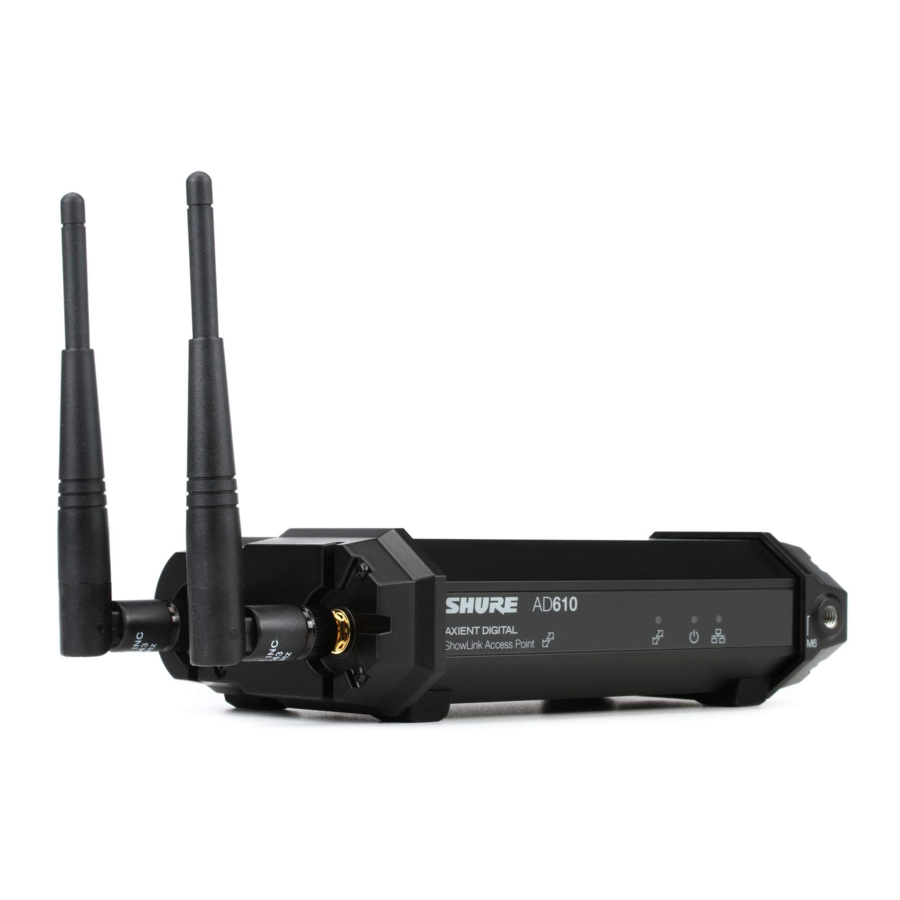
AD610 ShowLink Access Point
The AD610 ShowLink access point enables real-time remote control of all ShowLink-enabled Axient™ devices, including both digital and analog models. The access point allows comprehensive management of device parameters from the receiver or Wireless Workbench® using 2.4 GHz wireless network communication. All parameter changes occur without interruption to the performer.
Multiple access points can extend the operational range or increase the number of devices supported on the ShowLink network. The access point also features true diversity antenna inputs.
Features
- Real-time wireless remote control of up to 24 devices per ShowLink access point
- New RF design and true diversity antenna scheme for improved link performance
- Easy device authentication—Recognizes linked devices upon IR sync
- Automatic hand-offs between multiple access points extend operating range
- Automated channel selection—Independently scans 2.4 GHz frequency range and determines best channel for use
- Automatic frequency agility—Moves a ShowLink network to the best available 2.4 GHz channel in the event of signal degradation
- Wireless Workbench software supports networked control of all device functions and provides a ShowLink plot for viewing 2.4 GHz signal levels
- Receives power via Power over Ethernet (PoE) network connection or from an external power supply
- Versatile mounting options—Fits microphone stand adapters and has built in ¼" -20 and M6 x 1.0 threading for installation
- Backwards compatible with Axient analog transmitters and receiver
ShowLink Access Point Overview

- ShowLink 2.4 GHz detachable antennas
For 2.4 GHz signals - ShowLink Data Status LED (blue)
- ON Steady: Linked, no data transmission
- Flashing: Transmitting data. Rate of flashing indicates level of activity
- Power Status LED (green/amber/red)
- Steady Green: Power ON, power source = PoE
- Steady Amber: Power ON, power source = external power supply
- Red Flashing: Response to remote ID flash command
- Ethernet Status LED (green)
- ON Steady: Ethernet connected, no traffic
- ON Flashing: Ethernet connected, flashing corresponds to volume of data traffic
- ¼"-20 threaded mounting point
Use to wall-mount the access point - External power supply connector
Connection point for external power supply - Reset button
Press to restore factory settings - Ethernet port
For network connection and Class 1 PoE - Scanning antenna for channel agility
Scans the 2.4 GHz spectrum for the best frequency - M6 x 1.0 threaded mounting point
Use to mount access point to safety cable
Furnished Accessories
| Wireless Microphone Clip | WA371 |
| 5/8" to 3/8" Thread Adapter | 31A1856 |
| Shielded 25 foot Ethernet cable for ShowLink access point, RJ45-to-EtherCon connector | 95A15104 |
| Power Supply | PS43 |
 Note: Model availability depends on region. See your local Shure dealer or distributor for details.
Optional Accessories
| Directional 2.4 GHz patch antenna | AXT644 (available depending on regional regulations) |
ShowLink Basics
ShowLink Channels and 2.4 GHz Spectrum
ShowLink channels that enable remote control of Axient devices operate in the 2.40 to 2.484 GHz portion of the RF spectrum in accordance with the IEEE 802.15.4 protocol. Devices that share the 2.4 GHz spectrum, including Wi-Fi, are manufactured to efficiently share the spectrum and cause minimal interference. Both ShowLink and Wi-Fi use "listen before talk" technology to transmit short message packets only when needed to conserve bandwidth. Available spectrum, low interference, and global availability make the 2.4 GHz spectrum an ideal choice for hosting ShowLink channels.
Within the 2.4 GHz spectrum, 16 channels are available for ShowLink communication. To ensure reliable communication, the access point contains an internal scanning radio that analyzes the 2.4 GHz spectrum hundreds of times per second. If interference is detected, the access point uses channel agility to automatically switch to a clear channel within the spectrum. All devices associated with the access point will continue to communicate uninterrupted on the new ShowLink channel. If ShowLink goes offline for any reason, audio transmission will not be interrupted.
Coverage Area
The coverage area of the access point is approximately the same as the range of the linked device. Use the ShowLink Test feature in the receiver menu to map the boundaries of the coverage area. Multiple access points can be used to increase the coverage area or to expand coverage to multiple rooms.
ShowLink Test - ADX5D
ShowLink Test - AD4D or AD4Q
Device Capacity
A single access point supports up to 24 ShowLink-enabled Axient devices, including both Axient and Axient Digital models. Any ShowLink-enabled device within range of an active access point with available capacity will be automatically controlled by that access point. When multiple access points are used to increase device capacity or coverage area, device control is automatically divided between each access point. All changes in control between access points occur seamlessly and automatically, without requiring user intervention.
Device Control
An access point with available capacity will automatically control linked devices that are within the coverage area. Multiple access points automatically self manage to divide device control and maintain coverage. Transitions between access point control do not affect the transmission of the audio channel.
2.4 GHz Channel Agility to Avoid Interference
When interference is present from Wi-Fi or other devices sharing the spectrum, built-in channel agility automatically switches the access point and all controlled transmitters to a clear channel. Channel agility is able to avoid interference from most devices that operate in the 2.4 GHz spectrum, such as Wi-Fi or cell phones.
ShowLink Icon
The ShowLink icon appears on the home screens of a linked transmitter and receiver to indicate that the transmitter is within range of an access point making remote control possible. If a device is beyond the range of the access point, or if the receiver is offline, the icon will disappear, indicating a loss of ShowLink control.
Power
The access point is powered through Power Over Ethernet (PoE) enabled network ports. If PoE is not available, use an external power supply.
Power Over Ethernet
The Shure Ethernet switch and Axient rack components offer network ports with Power over Ethernet (PoE). The network port powers the access point as long as the host component is powered on.
- Insert a Cat 5 Ethernet cable into the Ethernet port located on the body of the access point.
- The Ethernet PoE connection supplies power for the access point.
External Power Supply (Optional)
")
If Power over Ethernet (PoE) is not available, power the access point using an external power supply.
- Connect the power supply to the external power supply jack.
- Tighten the locking ring to secure the plug.
- Plug the power supply AC line cord into an AC power source.
- Connect a Cat 5 Ethernet cable to the access point to provide a network connection.
Networking
Networking the access point using a DHCP-enabled router automatically assigns an IP address, simplifying network setup. The network connection allows the access point to share data with networked components and enables wireless control of the devices. To manually assign an IP address to the access point, use Wireless Workbench.
Reset Option

Pressing the reset button located on the bottom of the housing restores the access point to the following settings:
- IP Address Mode = DHCP
- Channel Agility = Enabled
- Device ID = AD610
- Device Association Tables will be cleared
Positioning the Access Point
- Provide a clear line of sight between the access point and devices. Mount the access point on a microphone stand or wall to elevate above obstructions.
- Position the antennas vertically for optimal performance. The swivel joint on each antenna allows a wide range of positioning to maintain a vertical alignment.
- If possible, move access point farther from other 2.4 GHz devices.
- This product is intended to be mounted with a ¼"-20 threaded insert and installed by a qualified person with suitable mounting means as appropriate for wall surface chosen.

Microphone Stand Mount

Horizontal Mount

Wall Mount
Network Mode
Set a host ID on the AD610 to connect to an ADX5D portable receiver in network mode. An AD610 with a host ID set grants access to ADX5Ds with a matching client ID.
- Update your AD610 to the latest firmware and download the latest version of Wireless Workbench.
- Connect the access point to your network using a Class 1 Power over Ethernet (PoE) port.
- Right-click the device in Wireless Workbench and open the device properties.
- Set a ShowLink network host ID (e.g. A.B.C.D).
Repeat this process for any other AD610s you have on the network that you want to act as a gateway for an ADX5D.
Then, set the client ID on your ADX5D.
Control and Configure the Access Point with Wireless Workbench
Using Wireless Workbench, you can do the following for your AD610.
- Edit device ID
- View connected devices
- View device capacity
- Disable channel agility for troubleshooting
- Set IP address mode: DHCP or manual
- Set IP address: Edit in manual address mode
- View and set subnet mask
- View MAC address
 Tip: The text color of the device ID for each transmitter in the Connected list indicates link quality:
- Green = Excellent
- Yellow = Good
- Red = Marginal
Hovering the cursor over the Device ID displays link quality ranked from 5 to 1.
Setting Power Levels
To adjust the power level, use Wireless Workbench. In locations with many competing 2.4 GHz sources, operating at a higher power level improves ShowLink performance and may extend range.
- Normal (default) = Operates at 8 dBm
- High = Operates at 18 dBm
- Open the Properties panel for the access point in Wireless Workbench.
- Click the Settings arrow, and select Network.
- Choose a power level and click Apply.
Note:
- Always check regional regulations before operating in the high power setting.
- Due to regulations, Channel 26 can only operate in the normal power setting.
Contact Customer Support
Didn't find what you need?
Contact our customer support to get help.
Specifications
General
Antenna Type
2 Omnidirectional 2.4 GHz
Capacity
/24 Axient ShowLink devices (AXT or ADX models)
Mounting Type
WA371 Mic Clip or 1/4-20 thread mount
Operating Temperature Range
-18°C (0°F) to 60°C (140°F)
Storage Temperature Range
-29°C (-20°F) to 74°C (165°F)
Dimensions
190 mm x 102 mm x 47 mm (7.48 in. x 4 in. x 1.85 in.) H x W x D, without antennas
Weight
464 g (16.3 oz.), without antennas
Housing
Extruded Aluminum
Power Requirements
| Power over Ethernet (PoE) Class 1 | 36 to 57 V DC/V AC |
| External Power Supply (if PoE is unavailable) | 15 V DC (600 mA), double insulated |
Ingress Protection Rating
IPX3
ShowLink
Network Type
IEEE 802.15.4
Frequency Range
2.40 to 2.4835 GHz (16 channels)
RF Output Power
10 dBm ERP / 20 dBm ERP (dependent on applicable country regulations)
Working Range
| Under typical conditions | 150 m ( 500 ft) |
| Line of Sight, outdoors for a single system | 500 m ( 1600 ft) |
Note: Actual range depends on RF signal absorption, reflection and interference.
Antenna Connection
Connectors
2 SMA (Shell=Ground, Center=Signal)
Impedance
50 Ω
Scanning Radio
Scanner RF Sensitivity
- 106 dBm, typical (integrated antenna)
Networking
Network Interface
Ethernet 10/100 Mbps
Network Addressing Capability
DHCP or Manual IP address (configurable using Wireless Workbench)
IMPORTANT SAFETY INSTRUCTIONS
- READ these instructions.
- KEEP these instructions.
- HEED all warnings.
- FOLLOW all instructions.
- DO NOT use this apparatus near water.
- CLEAN ONLY with dry cloth.
- DO NOT block any ventilation openings. Allow sufficient distances for adequate ventilation and install in accordance with the manufacturer's instructions.
- DO NOT install near any heat sources such as open flames, radiators, heat registers, stoves, or other apparatus (including amplifiers) that produce heat. Do not place any open flame sources on the product.
- DO NOT defeat the safety purpose of the polarized or grounding type plug. A polarized plug has two blades with one wider than the other. A grounding type plug has two blades and a third grounding prong. The wider blade or the third prong are provided for your safety. If the provided plug does not fit into your outlet, consult an electrician for replacement of the obsolete outlet.
- PROTECT the power cord from being walked on or pinched, particularly at plugs, convenience receptacles, and the point where they exit from the apparatus.
- ONLY USE attachments/accessories specified by the manufacturer.
- USE only with a cart, stand, tripod, bracket, or table specified by the manufacturer, or sold with the apparatus. When a cart is used, use caution when moving the cart/apparatus combination to avoid injury from tip-over.
![]()
- UNPLUG this apparatus during lightning storms or when unused for long periods of time.
- REFER all servicing to qualified service personnel. Servicing is required when the apparatus has been damaged in any way, such as power supply cord or plug is damaged, liquid has been spilled or objects have fallen into the apparatus, the apparatus has been exposed to rain or moisture, does not operate normally, or has been dropped.
- DO NOT expose the apparatus to dripping and splashing. DO NOT put objects filled with liquids, such as vases, on the apparatus.
- The MAINS plug or an appliance coupler shall remain readily operable.
- The airborne noise of the Apparatus does not exceed 70dB (A).
- Apparatus with CLASS I construction shall be connected to a MAINS socket outlet with a protective earthing connection.
- To reduce the risk of fire or electric shock, do not expose this apparatus to rain or moisture.
- Do not attempt to modify this product. Doing so could result in personal injury and/or product failure.
- Operate this product within its specified operating temperature range.

Explanation of Symbols
 | Caution: risk of electric shock |
 | Caution: risk of danger (See note.) |
 | Direct current |
 | Alternating current |
 | On (Supply) |
 | Equipment protected throughout by DOUBLE INSULATION or REINFORCED INSULATION |
 | Stand-by |
 | Equipment should not be disposed of in the normal waste stream |

Voltages in this equipment are hazardous to life. No user serviceable parts inside. Refer all servicing to qualified service personnel. The safety certifications do not apply when the operating voltage is changed from the factory setting.

Documents / ResourcesDownload manual
Here you can download full pdf version of manual, it may contain additional safety instructions, warranty information, FCC rules, etc.
Advertisement
Thank you! Your question has been received!


Need Assistance?
Do you have a question about the ShowLink AD610 that isn't answered in the manual? Leave your question here.