Table of Contents
Advertisement
Quick Links
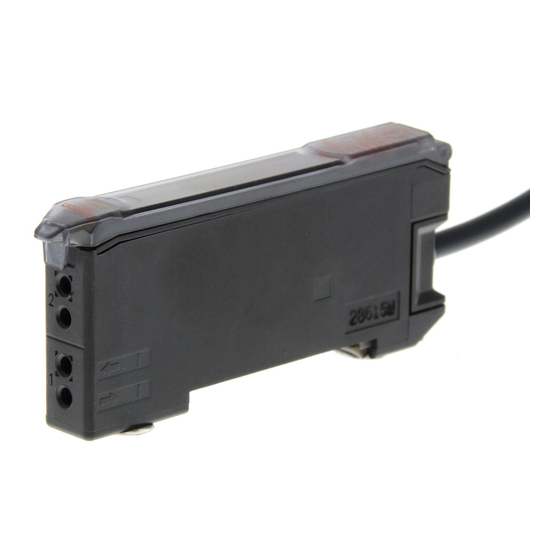
2-Channel Fiber Sensors
E3X-MDA
• The thinnest profile in the industry, with
only 5 mm per channel.
• AND/OR control output.
• Flexible control from the Mobile Con-
sole.
• The industry's first power tuning func-
tion in a digital amplifier
• Stable long term performance
due to Omrons's APC function.
• Two large easy to read displays
The remarkable new 2-channel amplifiers.
The Ultimate space saver!! Only 5mm for one
channel
Features
Bringing a new dimension to sensing...
...the 2-channel amplifier has arrived.
Photoelectric Sensors
Advertisement
Table of Contents

Related Manuals for Omron E3X-MDA11


Summary of Contents for Omron E3X-MDA11
- Page 1 2-Channel Fiber Sensors E3X-MDA The remarkable new 2-channel amplifiers. • The thinnest profile in the industry, with The Ultimate space saver!! Only 5mm for one only 5 mm per channel. • AND/OR control output. channel • Flexible control from the Mobile Con- sole.
- Page 2 Having problems gang-mounting Fiber Sensor Amplifier Units in tight spaces? 100 mm Half the Space Operation indicator Channel 1 display Incident level Operation indicator Channel 2 display Incident level 50 mm E3X-MDA...
- Page 3 Slimmest in the industry — 5 mm per channel. Patent pending Two Amplifiers squeezed into a body of width 10 mm. Checking alignment and mounting Remarkable space saving of approx. 50%. of LCD substrates Power saving of approx. 40%. (Savings per channel compared with existing products.) Emitting 2 ch...
- Page 4 Stable, long-term performance with OMRON’s APC function OMRON provides the industry's most stable long-term detection Highest Level of Stability by using new 4-element LEDs and an APC (Auto Power Control) circuit. In addition to our unique APC circuit used in the...
-
Page 5: Ordering Information
Ordering Information Amplifier Units Amplifier Units with Cables Model Item Appearance Functions NPN output PNP output 2-channel models AND/OR output E3X-MDA11 E3X-MDA41 Amplifier Units with Connectors Model Item Appearance Functions NPN output PNP output 2-channel models AND/OR output E3X-MDA6 E3X-MDA8... -
Page 6: Specifications
Model Quantity PFP-M Specifications Ratings/Characteristics Amplifier Units Type 2-channel models Model NPN output E3X-MDA11 E3X-MDA6 Item PNP output E3X-MDA41 E3X-MDA8 Light source (wavelength) Red LED (650 nm) 12 to 24 VDC ±10%, ripple (p-p) 10% max. Supply voltage 1,080 mW max. - Page 7 Type 2-channel models Model NPN output E3X-MDA11 E3X-MDA6 Item PNP output E3X-MDA41 E3X-MDA8 Operating:Groups of 1 to 2 Amplifiers: −25°C to 55°C Groups of 3 to 10 Amplifiers: −25°C to 50°C Groups of 11 to 16 Amplifiers: −25°C to 45°C...
-
Page 8: Output Circuits
(L/ON) (orange) Brown (orange) ch 2 ch 1 Operate Load (relay) Load Release Black (Between brown Control Load Photo- E3X-MDA11 output 1 and black) electric Orange 12 to Sensor E3X-MDA6 24 VDC main Incident light Control CH1/ circuit output 2... - Page 9 2. Control Output (AND, OR, Sync) and Time Chart for Timer Settings (T: Set Time) ON delay (AND) (AND) OFF delay (OR) (AND) One-shot (sync) (AND) Nomenclature Amplifier Units E3X-MDA@ Operation Keys Main Display (Red) Sub-Display (Green) Function setting operations Incident level, Threshold, function function, etc.
-
Page 10: Adjustment Methods
Adjustment Methods 1. Setting the Operation Mode 3.Setting Thresholds Manually (RUN Mode) The operation mode is set in SET mode. Refer to page A-373 5. Set- ting Functions in SET Mode. A threshold can be set manually. A threshold value can also be fine- tuned using manual setting after teaching. - Page 11 4-2. Teaching a Through-beam Fiber Unit without a Work- 4-3. Teaching a Reflective Fiber Unit without a Workpiece piece A value about 6% greater than the incident light level can be set as the threshold value. This method is ideal when using a Reflective A value about 6% less than the incident light level can be set as the Fiber Unit to detect workpieces so that detection is not influenced to threshold value.
- Page 12 5. Setting Functions in SET Mode * The default settings are shown in the transition boxes between functions. Teaching: Refer to page A-371 4. Teaching the Threshold Value (SET Mode). Set the Mode Selector to SET. Light Level and Threshold Display MODE Switch to desired function.
- Page 13 Output (To change the output content of channel 2) setting Output for each channel Output when the output is ON for both channels 1 and 2. DOWN MODE Output when the output is ON for either channel 1 or channel 2. Rising edge sync.
- Page 14 6. Convenient Functions ‘ 6-1. Zeroing the Digital Display The incident light level on the digital display can be set to 0. * Change the function to 0rst (zero reset) with the MODE key. The de- fault setting is PTUN. Set the Mode Selector MODE to RUN...
-
Page 15: Safety Precautions
Safety Precautions Note: In addition to the following precautions, please read and observe the common precautions for the instructions included with the product. Precautions for Correct Use Amplifier Unit • Joining and Removing Amplifier Units Joining Amplifier Units Installation 1. Mount the Amplifier Units one at a time onto the DIN track. •... -
Page 16: Fiber Connection
• Fiber Connection 2. Disconnecting Fibers Remove the protective cover and raise the lock button to pull out the The E3X Amplifier Unit has a lock button for easy connection of the fibers. Fiber Unit. Connect or disconnect the fibers using the following pro- cedures: 1. - Page 17 Dimensions Amplifier Units Amplifier Units with Cables E3X-MDA11 E3X-MDA41 First operation indicator Second operation indicator Vinyl-insulated round cable Main display Sub-display Standard length: 2 m* *Cable Specifications E3X-MDA11 A 4-dia., 2-conductor (conductor cross-sectional area: 0.2 mm ; insulation diameter: 1.1 mm)
- Page 18 Amplifier Units with Connectors First operation indicator Second operation indicator E3X-MDA6 E3X-MDA8 Main display Sub-display *1 The Mounting Bracket can also be With Mounting Bracket Attached used on this side. *2 Cable Diameters 3.9 × 3 = 11.7 32.8 4.0-mm dia. E3X-CN11 (3 conductors) 29.8 E3X-CN21 (4 conductors)
- Page 19 Slave Connectors E3X-CN12 2,000 E3X-CN22 10.7 E3X-CN12: 2.6 dia. E3X-CN22: 4 dia. 14.4 30± 10± 15.1 *E3X-CN12: A 2.6-dia., single-conductor, vinyl-insulated round cable (conductor cross- sectional area: 0.2 mm ; insulation diameter: 1.1 mm) is used. E3X-CN22: A 4-dia., 2-conductor, vinyl-insulated round cable (conductor cross- sectional area: 0.2 mm ;...
- Page 20 Cat. No. E11E-EN-01 In the interest of product improvement, specifications are subject to change without notice. OMRON EUROPE B.V. Wegalaan 67-69, NL-2132 JD, Hoofddorf, The Netherlands Phone: +31 23 568 13 00 Fax: +31 23 568 13 88 www.eu.omron.com E3X-MDA...