
Related Manuals for Lennox CS7500


Summary of Contents for Lennox CS7500
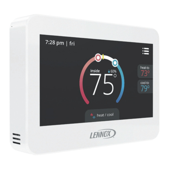
- Page 1 Installation and Setup Guide CS7500 Commercial Installation and Setup Guide 507506-03 02/2023 Supersedes 507506-02...
-
Page 2: Table Of Contents
Table of Contents Shipping and Packing List Shipping and Packing List ........2 Verify the following items have been included with in the packing: CS7500 Features ..........3 Product Dimensions ..........3 Quantity Item Installation .............4 CS7500 touchscreen, 7-day programmable thermostat with back Menu..............9... -
Page 3: Cs7500 Features
Compressor Short Cycle Protection CS7500 Features This thermostat is equipped with automatic com- The CS7500 is a commercial, electronic, 7-day, pressor protection to prevent potential damage due multi-stage, programmable, touchscreen thermo- to short cycling or extended power outages. stat. It also offers enhanced capabilities which in-... -
Page 4: Installation
WARNING • Shut off all power to system before installing. • Read this entire document, noting which Always turn off power at the main power source by instructions pertain to your equipment and switching the circuit breaker to the OFF position before installing or removing this thermostat. - Page 5 Hardware Installation Unpacked the thermostat and open the case with a thin-blade screwdriver. Place between wall base and unit and twist to separate unit from base. Select a location for the thermostat about 5 feet (1.5m) above the floor in an area with good air circulation at average temperature.
- Page 6 CUT OR DRILL A SMALL HOLE PULL ABOUT 3” OF THERMOSTAT FOR THERMOSTAT WIRING MOVE OUTER THERMOSTAT WIRE JACKET. ¾” x ¾” THIS WILL HELP IN MOSTAT WIRING TO MOSTAT TERMINALS (USE A LEVEL) ALIGN WALL PLATE TRIM 1/4” INSULATION FROM END OF EACH WIRE 1/4”...
- Page 7 Thermostat Installation with Wall Plate F - Place wall plate H - Attach back plate J - Attach thermostat to over holes in wall. to wall plate. back plate. G - Insert wall anchors I - Insert provided screws through back and wall through wall plate into wall.
- Page 8 In all applications, the commercial version of case. the CS7500 thermostat can only be used if the Configure thermostat and equipment for following installation criteria is met: system type, program the thermostat, and test •...
-
Page 9: Menu
Settings Menu Touch menu option from the home screen. menu notifications performance report Touch and hold the settings option on the menu. This will display the installer settings notice and then the installer settings menu. edit schedules installer settings < settings installer settings must be set Figure 2. -
Page 10: Installer Settings
Sensors Settings Installer Settings Use the following information to install sensors and setup in the user interface. Sets the thermostat for operation with either a heat pump or condenser unit and defines the number of < Indoor Outdoor compressor stages, sets the stage 3 output configu- ration, and the number of backup heat stages (gas, Outdoor sensor electric or both). - Page 11 Outdoor Sensor (small commercial split systems This thermostat can support one to five remote in- door temperature sensors. Users have three options only) to select from under Installer Settings > sensor set- An outdoor temperature sensor (X2658) is required tings > indoor sensor: for balance points and Humiditrol unit operations.
- Page 12 One sensor Two sensors - - (1) 47W36 (2) 47W37 Three sensors - Four sensors - (2) 47W36 and (4) 47W36 (1) 47W37 Five sensors - (3) 47W36 and (2) 47W37 Figure 6. Indoor Sensor Configurations (Option 2, 20K Setting)
- Page 13 Residual Cool High Balance Point Default is 50°F. Adjustable range is -38°F to 75°F. Default is 0 seconds. This is the time, in seconds, that the fan runs after a call for cooling is satisfied in NOTE: The high balance point minimum range is order to deliver any residual cooling ability from the adjustable to within +2°F of the low balance coil and ductwork into the conditioned space.
- Page 14 Touch < to return to previous menu. NOTE: Smooth Set Recovery and SSR STG 2 Lock Out operations vary depending on Temperature Offset equipment (see table 1). Default is 0°F. This setting can be used to offset the SSR Stage 2 Lock Out displayed space temperature by up to +/- 5°F.
- Page 15 Equipment Available When SSR is enabled then SSR When SSR is disabled then Stage 2 lock out is automatically SSR Stg 2 lock-out setting is enabled. disabled. Single-stage heat pump with • Run heat pump (Y1) only • Run heat pump (Y1) until a single-stage gas or oil backup second stage heating demand is •...
- Page 16 Equipment Available When SSR is enabled then SSR When SSR is disabled then Stg 2 lock out is automatically SSR Stg 2 lock-out setting is enabled. disabled. Two-stage heat pump with: • Run heat pump (Y1/Y2). • Run HP (Y1/Y2) until a second- stage demand is needed which •...
- Page 17 Stage 2 Through 4 Delays H/C Stages Locked In (Where applicable) If STG DELAY TIMERS is When disabled the heat/cool stages are turned off turned ON, the default delay is 20 minutes but can separately). When enabled (default), heat/cool stag- be programmed from 5 to 120 minutes in 5-minute es are turned off together.
- Page 18 1st stage 1st stage Stages Stg1 Differential Locked = 2nd stage 2nd stage Stg2 Differential 1st stage 1st stage Stages Stg1 Differential Locked = 2nd stage 2nd stage Stg2 Differential SP -1.5 SP -1.0 SP -0.5 SP +1.0 SP +1.5 POINTS: Figure 7.
- Page 19 1st stage 1st stage Stages Stg1 Differential Locked = 2nd stage 2nd stage Stg2 Differential 1st stage 1st stage Stages Stg1 Differential Locked = 2nd stage 2nd stage Stg2 Differential POINTS: SP -3.0 SP -2.5 SP -2.0 SP -1.5 SP -1.0 SP -0.5 SP +0.5 Figure 9.
- Page 20 1st stage 1st stage Stages Stg1 Differential Locked = 2nd stage 2nd stage Stg2 Differential 3rd stage 3rd stage Stg3 Differential 4th stage 4th stage Stg4 Differential 1st stage 1st stage Stages Stg1 Differential Locked = 2nd stage 2nd stage Stg2 Differential 3rd stage 3rd stage...
- Page 21 1st stage 1st stage Stages Stg1 Differential Locked = 2nd stage 2nd stage Stg2 Differential 3rd stage 3rd stage Stg3 Differential 1st stage 1st stage Stages Stg1 Differential Locked = 2nd stage 2nd stage Stg2 Differential 3rd stage 3rd stage Stg3 Diff.
- Page 22 1st stage 1st stage Stages Stg1 Differential Locked = 2nd stage 2nd stage Stg2 Differential 3rd stage 3rd stage Stg3 Differential 4th stage 4th stage Stg4 Differential 1st stage 1st stage Stages Stg1 Differential Locked = 2nd stage 2nd stage Stg2 Differential 3rd stage 3rd stage...
- Page 23 Compressor Protection To set a reminder go to the User Settings screen Default is ON and it can be turned OFF, however and select reminders. The reminder setting screen only for one compressor cycle and then it will revert will appear and a list all of the predefined reminders back to ON.
- Page 24 The thermostat Time Heating Cooling Fan Setting default setting is Occ1 70°F (21°C) 76°F (24°C) Auto two period only. To use four periods, Unocc1 55°F (10°C) 85°F (29.5°C) Auto change the appropriate setup Occ2a 70°F (21°C) 76°F (24°C) Auto parameter. Unocc2a 62°F (17°C) 85°F (29.5°C)
-
Page 25: Dehumidify Mode
Dehumidify Terminal D State NOTICE! Mode Setting Normal, Max or De-energized for Risk of equipment damage. Humiditrol dehumidification and energized Can cause compressor failure. for all other modes. In dual fuel system application, do not turn on heat De-energizing D terminal is used pump and furnace at the same time in system test to reduce the speed of the indoor mode. - Page 26 Normal Humiditrol® In this mode, dehumidification occurs if these con- This setting is for commercial split systems only. If ditions are met and signals are present at specific Humiditrol is enabled in the installer settings, then terminals: this adjustment affects over-cooling operation. Dehumidification been enabled...
-
Page 27: Economizer
In this case, 24VAC is removed from the D terminal Relative Humidity controls to within 3% on either and Y1, Y2, and Y3 terminal (if available) becomes side of RH set point. activated with 24VAC. This cycles the indoor vari- When dehumidify mode is in NORMAL or MAX or, able speed motor to the dehumidification speed and HUMIDITROL, “D”... -
Page 28: Unit Part (Catalog) & Serial Numbers
A label on the back of the thermostat is visible through an opening in the back of base plate. This identifies the Lennox Catalog Number, Part Number and Serial Number. Separate the base plate from the thermostat to see additional manufacturing in- formation. -
Page 29: Start-Up Sequence Of Operations
Start-Up Sequence of Operations START HUMIDITROL RUN EQUIPMENT there a cooling Is indoor demand ING MODE temperature > 2ºF above heating set point RUN EQUIPMENT there a heating demand ING MODE indoor temp. greater than the heat fort Adjust setting setpoint plus the cool setpoint divided by 2? there a... -
Page 30: Diagnostic Information
Diagnostic Information Error Screen Text Priority Message Condition System Action Action to Clear Code 0: high Type / Recovery 1: middle Condition 2: low All stages of heat Once temperature High temperature are turned off by drops below 96°F protection when high safety relay. - Page 31 Error Screen Text Priority Message Condition System Action Action to Clear Code 0: high Type / Recovery 1: middle Condition 2: low For Outdoor Temperature Sensor: No Humiditrol or Humidity operation. D terminal stays activated and other operation will continue to operate.
- Page 32 Error Screen Text Priority Message Condition System Action Action to Clear Code 0: high Type / Recovery 1: middle Condition 2: low humidity sensor critical With humidifier All humidity operation error or dehumidifier) will stop and the and conditions reading for humidity are as follows: will not be valid.
-
Page 33: Reminder Information
Reminder Information Error Screen Text Message Action to Clear / Recovery Condition Code Type replace media filter replace UV lamp replace humidity pad Touch either done to clear the reminder or remind routine system check-up reminder later button. replace metal insert for pure air user editable user editable... -
Page 34: Supported Configurations
Supported Configurations This thermostat support air conditioner and heat pump systems with one or two speed compressors. It also supports dual-fuel and Humiditrol accessory. For all possible configuration see table below. Setup Backup/ Comp. Backup/ Heat Cool 3nd Cool O/B/Y3 Indoor Stages Indoor... -
Page 35: Installation Checklist
Setup Backup/ Comp. Backup/ Heat Cool 3nd Cool O/B/Y3 Indoor Stages Indoor Stages Heat Heat Heat Heat Stages Staging Cool Cool Stage relay Heat Heat Stage Stage Stage Stage Heat Heat Control Stage Stage Stages Stage Stage NONE Y1+Y2 GAS/OIL Dedicated (Y3) Y1+Y2 Y1+Y2+Y3 OR ELEC. - Page 36 Index Wall Plate 3 Economizer 27 Energy Saving Default 24 Balance Points, Low, High 13 Features 3 Compressor Protection 23 Compressor Short Cycle Protection 3 Configuration 17 H/C Stages Locked In 17 Contractor Information 14 Humidity Offset 14 Custom Reminders 23 Humidity Sensor Fault 27 Humidity Settings 23 Deadband 13...
- Page 37 Remote Temperature Room Sensor 11 Unit Part Reset Settings 23 Catalog 28 Residual Cool 13 Wall anchors 2 Sensors Settings 10 Serial Numbers 28 Smooth Set Recovery(SSR) 13 SSR Stage 2 Lock Out 14 Stage 1 Differential 16 Stage 2 HP Lock Temp 17 Stage 2 Through 4 Delays 17 Stage 2 Through 4 Differential 16 Stage Delay Timer 16...