Table of Contents
Advertisement
E2005 Lennox Industries Inc.
Dallas, Texas, USA
®
Elite
Series 1 Heat / 1 Cool Programmable
This thermostat is to be installed by a qualified service technician or
other qualified agency in accordance with the manufacturer's instruc-
tions, all codes, and requirements of the authority having jurisdiction.
505,043M
10/2005
Touch Screen Thermostat
WARNING
INSTALLATION
INSTRUCTIONS
Advertisement
Table of Contents

Related Manuals for Lennox X4146


Summary of Contents for Lennox X4146
- Page 1 INSTALLATION INSTRUCTIONS E2005 Lennox Industries Inc. Dallas, Texas, USA ® Elite Series 1 Heat / 1 Cool Programmable Touch Screen Thermostat WARNING This thermostat is to be installed by a qualified service technician or other qualified agency in accordance with the manufacturer’s instruc- tions, all codes, and requirements of the authority having jurisdiction.
-
Page 2: Table Of Contents
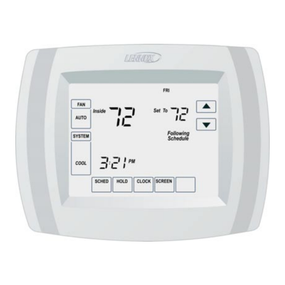
• Hammer General • Electrical tape ® The Lennox Elite Series X4146 ther- mostat provides control for single− Thermostat Location stage heating and cooling. The ther- mostat may be used to control either a Install the thermostat about 5 feet conventional HVAC system which in- (1.5m) above the floor in an area with... -
Page 3: Remove Existing Thermostat
Do not allow the thermostat wires Remove Existing Thermostat to fall behind the drywall. If this thermostat is being used to re- place an existing thermostat, remove the old thermostat: WARNING 1 − Turn off power at the heating and/or cooling system fuse/circuit... -
Page 4: Thermostat Installation
7 − Secure the wallplate using the pro- Thermostat Installation vided screws. The thermostat may be installed hori- zontally in a 4 in. X 2 in. (101.6 mm X 50.8 mm) wiring box or on the wall us- ing the provided anchors. DRILLED 1 −... -
Page 5: Led Indicator
1 − Make wiring connections per the TERMINAL appropriate wiring diagram on BLOCK LETTER pages 6 and 7. Refer to the table DESIGNATIONS below for terminal designations. WALLPLATE Terminal Description First−stage heating WIRE HOLE (conventional) Remote outdoor sensor Remote outdoor sensor 24V power LABELED WIRES Reversing valve... -
Page 6: Field Wiring Diagrams
Field Wiring Diagrams TYPICAL COOL ONLY SYSTEM TYPICAL CONVENTIONAL SINGLE−STAGE HEAT / COOL SYSTEM Page 6... - Page 7 Field Wiring Diagrams (Continued) TYPICAL HEAT ONLY SYSTEM TYPICAL HEAT ONLY SYSTEM WITH FAN Page 7...
-
Page 8: Install Batteries
WALLPLATE Install Batteries 1 − Install three provided AAA alkaline batteries in the back of the thermo- PINS ON BACK OF stat as shown. THERMOSTAT TERMINAL SCREW BACK OF THERMOSTAT BLOCK Set Calendar and Clock This thermostat is designed to auto- matically keep the current time and date in memory for up to ten years, un- BATTERIES... -
Page 9: Installer Set−Up
Installer Set−Up ADVANCE TO NEXT INSTALLER INSTALLER SET−UP SET−UP NUMBER Use the following steps and the Install- CURRENT SETTING er Set−Up menu to match the thermo- stat to the HVAC system. 1 − Press and release the SYSTEM key. 2 − Press and hold the two blank keys on either side of the center blank key for approximately five seconds. - Page 10 Installer Installer Selection Description Notes Set−Up Set−Up (Factory setting in bold print) Number Name Select first two digits of current calendar Date year (20 for 2005, etc.) 0120 (Year/first) Factory setting = 20. Select last two digits of current calendar Date 0130 year (05 for 2005, etc.);...
- Page 11 Installer Installer Selection Description Notes Set−Up Set−Up (Factory setting in bold print) Number Name Cycles per Hour 3 − Recommended setting for (cph) 1st compressors. Factory setting. 0220 Stage Settings of 1 − 6 cph available. Compres- 1 − Recommended for use with steam and gravity.
- Page 12 Installer Installer Selection Description Notes Set−Up Set−Up (Factory setting in bold print) Number Name Set to 0 in 0 − Daylight savings disabled. areas that Daylight do not do not Daylight 0330 Savings follow 1 − Daylight savings enabled. daylight Factory setting.
- Page 13 Installer Installer Selection Description Notes Set−Up Set−Up (Factory setting in bold print) Number Name 0 − Conventional Recovery −− System starts recovery at programmed time. Adaptive Adaptive 1 − Adaptive Intelligent Recovery −− Sys- 0530 Intelligent tem starts recovery early so that set- Recovery point is reached by the start of the pro- gram period.
- Page 14 Installer Installer Selection Description Notes Set−Up Set−Up (Factory setting in bold print) Number Name 0 − Keypad unlocked −− all functions are available. Factory setting. 1 − Keypad partially locked −− only temp. up and down keys and ability to enter installer Keypad 0670 set−up mode and modify set−up selections...
-
Page 15: System Test
System Test The system test function allows the in- test selections. staller to check the HVAC system after 4 − The installer test number is dis- the thermostat set−up has been com- played on the left−hand side of the pleted. The system test function is ac- screen. -
Page 16: Troubleshooting
Troubleshooting Symptom Possible Cause Action Check to see that there is 24V between R and C terminals. Display does not come Display does not come Thermostat is not being Thermostat is not being powered. Check to see that batteries are properly installed.