Greenlee 200EP-G, 200B-G - Tone Probe Manual
- Instruction manual (49 pages) ,
- Instruction manual (2 pages)
Advertisement
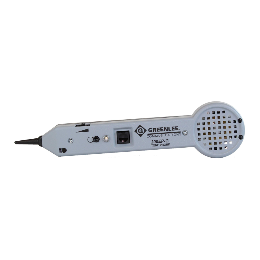
Description
The 200B-G and 200EP-G Tone Probes, when used in conjunction with any Greenlee tone generator, are designed to identify and trace wires or cables within a group without damaging the insulation.

Features include:
- Resistive plastic carbon-fiber tip to prevent accidental shorts when probing wires
- Adjustable volume sensitivity control
- Battery compartment
- Recessed terminal ports for handset connection*
- Spring-loaded ON/OFF/flashlight* button
- LED*
- Headset jack (acoustically protected)*
- High power flashlight* * 200EP-G only.
Safety
Safety is essential in the use and maintenance of Greenlee tools and equipment. This instruction manual and any markings on the tool provide information for avoiding hazards and unsafe practices related to the use of this tool. Observe all of the safety information provided.
Purpose of this Manual
This instruction manual is intended to familiarize all personnel with the safe operation and maintenance procedures for the Greenlee 200B-G and 200EP-G Tone Probes.
Keep this manual available to all personnel.
Replacement manuals are available upon request at no charge at www.greenlee.com.
Operation
- Connect the test set leads of a Greenlee tone test set to the subject pair. In the case of a single conductor, connect the RED lead to the subject wire and the BLACK lead to earth or an independent equipment ground. Refer to the instruction manual provided with the tone generator for details. Refer to Figure 2.

- Place the test set in the TONE position.
- To activate the probe, press and hold the ON/OFF button. This button must remain depressed to operate. Hold the tip of the probe near the tone generator and listen for the tone. This verifies that the tone generator is working and identifies the sound of the tone (steady, warbling, etc.).
- Once activated, the volume control can be adjusted to suit the environment. Reception can be increased to overcome noise (e.g., vehicular traffic, airplanes, or engine room) or decreased to reduce interference (e.g., computer/date hum or AC buzz).
- The 200EP-G is equipped with recessed terminal ports for connecting a lineman's handset. Attaching the handset automatically activates the amplifier. The handset must be in the TALK position to receive the tone.
- Touch the tip of the probe to the insulation of each suspect conductor. Reception of tone will be loudest on the subject wire and detection may be improved by separating the wires from the group. If more than one pair or single conductor is carrying the tone, decrease the volume until only the subject conductor is left with tone, insuring that positive identification has been made.
- When pair tracing, in order to confirm that the correct pair has been identified, separate the two wires. The signal will be as loud on each of the pair wires and will NULL halfway between the two wires.
- On the 200EP-G, press the ON/OFF button further to its second position to turn the flashlight ON. Reduce pressure slightly to turn it back OFF.

Note: To use the 200EP-G without pressing the ON/OFF button, connect a jumper, a telephone test set (in TALK mode), or headset to the recessed tabs near the speaker.
Specifications
Electrical
Gain (nominal): 30 dB
Input Impedance (nominal): 100 MΩ
Probe Tip Resistance (min):
- Metal Tip: 0 Ω
- Plastic Tip: 300 Ω
Headset: 3.5 mm stereo plug; 8 ohms minimum
Battery: One 9 VDC (NEDA 1604, JIS 006P, or IEC 6LR61)
Battery Life (nominal): 50 hours
Physical
Length: 231 mm (9.0")|
Width: 55 mm (2.2")
Depth: 28 mm (1.1")
Weight: 145 g (5.2 oz)
Operating/Storage Conditions
Temperature: 0°C to 50°C (32°F to 122°F)
Maintenance
Battery Replacement
- Turn the unit off.
- Remove the screw and then the battery cover.
- Replace the battery (observe polarity).
- Replace the battery cover and the screw.
DO NOT OVERTIGHTEN SCREW.
Tip Replacement
- Turn the unit off.
- Remove the two slotted screws and CAREFULLY separate the two halves of the housing. Do not strain the exposed wire leads.
- Replace the tip.
- Re-assemble the housing. DO NOT OVERTIGHTEN SCREWS.
Cleaning
Periodically wipe with a damp cloth and mild detergent; do not use abrasives or solvents.

Documents / Resources
References
Download manual
Here you can download full pdf version of manual, it may contain additional safety instructions, warranty information, FCC rules, etc.
Advertisement
Thank you! Your question has been received!


Need Assistance?
Do you have a question about the 200EP-G that isn't answered in the manual? Leave your question here.