Table of Contents
Advertisement
Quick Links
Advertisement
Table of Contents

Related Manuals for Greenlee 560XL


Summary of Contents for Greenlee 560XL
- Page 1 Fiber Optic Power Meter 850/1300 nm LED Source 1310/1550 nm Laser Source 0500-01 REV A 560XL 570XL 580XL Read and understand all of the instructions and safety information in this manual before operating or servicing this tool. © 2005 Greenlee Textron Inc. 8/05...
-
Page 2: Table Of Contents
580XL Laser Source........9 560XL Power Meter ........10 General Information . -
Page 3: Description
• The 560XL power meter measures optical power at 850 nm, 1300 nm, 1310 nm, and 1550 nm and can store reference power levels. -
Page 4: Important Safety Information
Important Safety Information This symbol is used to call your attention to hazards or unsafe practices which could result in an injury or property damage. The signal word, defined below, indicates the severity of the hazard. The message after the signal word provides informa- tion for preventing or avoiding the hazard. - Page 5 Failure to observe these precautions may result in injury. Electric shock hazard: Contact with live circuits could result in severe injury or death. CAUTION LASER LIGHT DO NOT STARE INTO BEAM CLASS I LASER PRODUCT 560XL • 570XL • 580XL...
- Page 6 Important Safety Information Electric shock hazard: • Do not insert batteries with the polarity reversed. Do not mix batteries of different manufacturers or types, e.g., alkaline and non-alkaline. • Do not open the case of the unit for any reason. It contains no user-serviceable parts.
-
Page 7: Introduction
Please account for and inspect each item while unpacking and preparing the instrument for use. If the instrument received is damaged, contact Greenlee. Refer to the instructions under “Warranty.” Keep the shipping carton in case re-shipment is required for any reason, e.g., annual recalibration. -
Page 8: Specifications
Specifications 570XL Series 850/1300 nm Dual-Wavelength LED Sources* Center wavelength (FWHM) Nominal Range Max. spectral width (FWHM) 55 nm Stability, 1 hour Power output, 62.5/125 µm GI MM** Power output uncertainty Optical connector interface Functions Modulation frequencies Power requirements Battery life Environment Operating temperature Storage temperature... -
Page 9: 580Xl Laser Source
10 minutes. The initial reference power is measured at approximately 25 °C. *** With return loss > 30 dB. † Power is 3 dB lower in modulated mode. 560XL • 570XL • 580XL 1310 nm 1280 to 1340 nm 1520 to 1580 nm < 5 nm ±0.2 dB... -
Page 10: 560Xl Power Meter
560XL Series Optical Power Meters* Detector size and composition Calibrated wavelengths Measurement range Linearity: +3 to -3 dBm -3 to -50 dBm -50 to -60 dBm Absolute accuracy Wavelength dependence (typical): 820 to 880 nm 975 to 985 nm 1270 to 1330 nm... -
Page 11: General Information
This section provides general instructions on how to use the XL fiberTOOLS instruments. If circumstances require that the instruments be serviced and main- tained in-house, contact Greenlee for technical assistance. Battery Installation or Replacement All XL fiberTOOLS instruments are powered by two AA-size 1.5 volt alkaline batteries. - Page 12 Battery Installation or Replacement (cont’d) To replace the batteries, follow these steps: 1. Carefully remove the protective rubber cover. 2. Turn the instrument onto its front face, then open the battery com- partment by pressing on the center of the cover (Step 1 below) while pulling on the sides (Step 2 below).
-
Page 13: Auto-Shutoff Feature
70 minutes. To disable the auto-shutoff feature, do the following: 1. Press the [ON/OFF] and [dB/dBm] keys simultaneously while turn- ing the instrument on. The auto-shutoff feature is now disabled. 2. To re-enable the auto-shutoff feature, cycle the power off and on. 560XL • 570XL • 580XL... -
Page 14: Snap-On Connector (Soc) Interface For 580Xl
Snap-On Connector (SOC) Interface for 580XL SOC interfaces and adapters offer superior repeatability and are com- patible with most industry standard fiber optic connectors. SOC adapters can also be quickly removed from the interface to permit cleaning of the detector window in accordance with the following instructions. -
Page 15: Operation
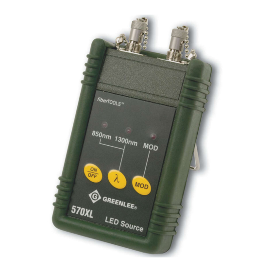
Frequency select: This switch, located inside the battery compart- ment, sets the modulation frequency. See “Setting the Source Modulation Frequency” section. Output interfaces: Light output is emitted from these interfaces. 560XL • 570XL • 580XL Wavelength select key Output interfaces... -
Page 16: 580Xl Laser Source
580XL Series Dual-Wavelength Laser Sources Removable rubber cover Wavelength/ low battery indicators ON/OFF [ON/OFF] key: This key turns the unit on and off. When the unit is first turned on, the 1310 nm laser is automatically selected in continuous wave mode. [λ] key: This key toggles the instrument between the 1310 nm and 1550 nm lasers. -
Page 17: 560Xl Power Meter
This is indicated by the “r” annunciator appearing in the lower right-hand corner of the LCD screen. Note: The 560XL Series optical power meters incorporate multi- wavelength reference storage capability. This enables a 0 dB reference value to be stored in non-volatile memory for each calibrated wave- length. -
Page 18: Setting The Source Modulation Frequency
ALWAYS BE SET TO THE “OP” POSITION. TAMPERING WITH THE CAL/OP SWITCH WILL VOID CALIBRATION OF THE INSTRUMENT. Input interface: This is the optical input connector. All 560XL Series optical power meters are equipped with a SOC interface. Setting the Source Modulation Frequency All 570XL Series LED sources and 580XL Series laser sources are shipped with the modulation frequency switch set at 1 kHz. -
Page 19: Applications
(Method B), and OFSTP-14 (Method B). 1. Connect an appropriate light source to the optical power meter using a suitable reference cable with a length of about 2 to 3 meters (6 to 10 feet), as shown below. 560XL • 570XL • 580XL... - Page 20 One Test Jumper Method: Connector Loss (cont’d) 2. Ensure that the light source is in continuous wave (CW) output mode. Set the optical power meter to the appropriate wavelength (using the [λ] key) and to dBm units (using the [dB/dBm] key). Note that the dBm output of the reference cable should be within acceptable limits.
- Page 21 The optical power meter reads the connector/cable loss in dB. The example below displays a connector/cable loss of -0.15 dB. 560XL • 570XL • 580XL Cable/connector under test...
-
Page 22: Two Test Jumper Method: Link Loss
Two Test Jumper Method: Link Loss Source Source Test jumper 1 Power meter Test jumper 2 Power meter Cable plant... - Page 23 FORWARD LOSS (dB) = P1 – P3 Test jumper 1 Source 2. Connect a light source and optical power meter to the respective patch panel ports using the test jumpers, as shown above. 560XL • 570XL • 580XL Cable plant jumper 2 Test Power meter...
- Page 24 Two Test Jumper Method: Link Loss (cont’d) 3. Using the formula shown above, take the dBm reading on the optical power meter (P3) and the nominal source output value, corresponding to the light source in use. Note: Make sure the optical power meter supports the wavelength of the light source in use.
-
Page 25: Dual-Wavelength Sm Loss Measurements
1310 nm and 1550 nm transmission windows. Therefore, dual- wavelength acceptance testing is required to be performed at the present time. The following test procedure complies with TIA/EIA-526-7 (OFSTP-7, Method A), Attenuation of Installed Single-mode Fiber Link. 560XL • 570XL • 580XL... - Page 26 Dual-Wavelength SM Loss Measurements (cont’d) 1. Connect the 580XL dual laser source to the 560XL optical power meter using a suitable reference cable at least 3 meters (10 feet) long. Turn on both instruments and set the wavelength to 1310 nm on the dual laser source, and 1310 nm on the optical power meter.
- Page 27 Record the dB reading on the optical power meter. This is the link loss at 1550 nm. 8. Go to the next fiber and repeat from Step 1. Test jumper 1 Source 560XL • 570XL • 580XL SM cable plant Test jumper 2 Power meter...
-
Page 28: Warranty
Greenlee Textron Inc. warrants to the original purchaser of these goods for use that these products will be free from defects in workmanship and material for their useful life, excepting normal wear and abuse. This warranty is subject to the same terms and conditions contained in Greenlee Textron Inc.'s standard one-year...