Table of Contents
Advertisement
Quick Links
INSTRUCTIONS-PARTS LIST
This manual contains important
warnings and information.
READ AND KEEP FOR REFERENCE.
INSTRUCTIONS
Dyna-Star
HYDRAULIC RECIPROCATOR & PUMP
1500 psi (10 MPa, 103 bar) Maximum Hydraulic Input Pressure
375 psi (2.6 MPa, 26 bar) Maximum Fluid Outlet Pressure
1/4:1 RATIO UNIVERSAL PUMP AND RECIPROCATOR
Model 236-753, Series A, stubby length
RECIPROCATOR ONLY
Model 236-751, Series B
WARNING
The pump is designed to dispense lube products
only. Any other fluids can cause unsafe operating
conditions and result in component rupture, fire or
explosion which could cause serious injury, includ-
ing fluid injection.
Table of Contents
. . . . . . . . . . . . . . . . . . . . . . . . . . . . . . . . . . . . . .
. . . . . . . . . . . . . . . . . . . . . . . . . . . . . . . . . . . .
. . . . . . . . . . . . . . . . . . . . . . . . . . . . . . . . . . . . . . . . . . . . . . .
. . . . . . . . . . . . . . . . . . . . . . . . . . . . . . . . . . . . . .
. . . . . . . . . . . . . . . . . . . . . . . . . . . . . . . . . . . . . .
. . . . . . . . . . . . . . . . . . . . . . . . . . .
Parts List & Drawing
Universal 1/4:1 Ratio Displacement Pump
. . . . . . . . . . . . . . . . . . . . . . . . . . . . . . . .
. . . . . . . . . . . . . . . . . . . . . . . . . . . . . . . . . .
. . . . . . . . . . . . . . . . . . . . . . . . . . . . . . . .
. . . . . . . . . . . . . . . . . . . . . . . . . . . . . . . . . . . . .
. . . . . . . . . . . . . . . . . . . . . . . . . .
GRACO INC. P.O. BOX 1441 MINNEAPOLIS, MN 55440-1441
. . . . . . . . . . . . . . . . . . . . .
. . . . . .
. .
COPYRIGHT 1994, GRACO INC.
Graco Inc. is registered to I.S. EN ISO 9001
First choice when
quality counts.
2
5
8
10
11
14
18
Patent No. 4,383,475
19
Foreign Patents Pending
20
Patent 1984 Canada
22
Brevete 1984
23
23
24
24
308-390
Rev. C
Supersedes Rev. A
Includes Rev. B
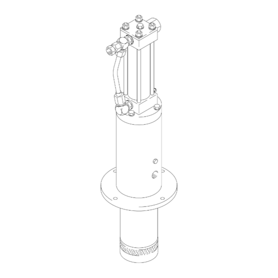
Model 236-753 shown
Advertisement
Table of Contents

Related Manuals for Graco Dyna-Star A Series


Summary of Contents for Graco Dyna-Star A Series
-
Page 1: Table Of Contents
......Model 236–753 shown GRACO INC. P.O. BOX 1441 MINNEAPOLIS, MN 55440–1441 COPYRIGHT 1994, GRACO INC. Graco Inc. is registered to I.S. EN ISO 9001... -
Page 2: Warnings
This equipment is for professional use only. Read all instruction manuals, tags, and labels before you operate the equipment. Use the equipment only for its intended purpose. If you are not sure, call your Graco distributor. Do not alter or modify this equipment. - Page 3 WARNING WARNING FLUID INJECTION HAZARD Spray from the dispensing valve, leaks or ruptured components can inject fluid into your body and cause extremely serious injury, including the need for amputation. Fluid splashed in the eyes or on the skin can also cause serious injury. Fluid injected into the skin might look like just a cut, but it is a serious injury.
- Page 4 WARNING WARNING FIRE AND EXPLOSION HAZARD Improper grounding, poor ventilation, open flames or sparks can cause a hazardous condition and result in a fire or explosion and serious injury. Ground the equipment and the object being sprayed. Refer to Grounding on page 7. If there is any static sparking or you feel an electric shock while using this equipment, stop spraying immediately.
-
Page 5: Installation
Typical Installation – Suction Feed System Hydraulic Fluid Control, 236–864 Return Line Shutoff Valve Hydraulic Supply Line (Use only (See Manual 308–395) Hydraulic Inlet, 3/8 npt GRACO hydraulic power supply) Porous Plug (Weep tube optional) Hydraulic Supply Line Shutoff Material Supply Fluid Dispenser Outlet Valve... - Page 6 Installation Pump Accessories CAUTION Suction T ube Kit Keep The Hydraulic System Clean A suction tube kit is available for siphoning from 55 The hydraulic supply system must be kept clean gallon containers. at all times to reduce the risk of damaging the Intake T ube (not shown) reciprocator hydraulic power supply.
- Page 7 Installation Hydraulic Fluid Control Grounding To reduce the risk of static sparking, ground the pump. WARNING Check your local electrical code for detailed grounding instructions for your area and type of equipment. Always turn off the hydraulic supply side valve (K in Fig.
-
Page 8: Operation
WARNING Recommended Hydraulic Oil INJECTION HAZARD The system pressure must be manually Use Graco-approved Hydraulic Oil or a premium, relieved to prevent the system from ISO grade 46 petroleum-based hydraulic oil con- taining rust and oxidation inhibitors and anti-wear starting or spraying accidentally. Fluid agents. - Page 9 Operation Starting the Pump If the Reciprocator Leaks at the Fluid Fittings WARNING Tighten the fittings (16, 17, 25), which are self-sealing and have replaceable o-rings. If leaking persists, Maximum Working Pressures change the o-rings. See Fig. 3. To reduce the risk of serious bodily injury includ- ing fluid injection and splashing in the eyes or on the skin, which may be caused if a component ruptures:...
-
Page 10: Troubleshooting
Troubleshooting Note: Check all possible problems and solutions WARNING before disassembling the pump or reciprocator. To reduce the risk of serious injury whenever you are instructed to relieve pressure, always follow the Pressure Relief Procedure on page 8. PROBLEM CAUSE SOLUTION Pump will not run. -
Page 11: Service
Service Replacing Base Packing in Reciprocator See Fig. 4. NOTE: Replace these seals if fluid leaks excessively through the porous plug (107), see Fig. 5. This procedure can be done without disassembling the entire reciprocator. 1. Relieve the pressure. WARNING To reduce the risk of serious injury whenever you are instructed to relieve pressure, always follow the Pressure Relief Procedure on page 8. - Page 12 Service Disconnecting Reciprocator and Displacement Pump and Replacing Throat Seals. See Fig. 5. 1. Flush the pump if possible, and stop it with the During assembly, screw the piston rod in the lowest position. connecting rod (45 in Fig. 8) into the piston rod (116) first.
- Page 13 Service Assembly after Replacing Throat Seals See Fig. 5. 1. Apply fresh grease to the new throat seal (110) and the mating groove in the base (115). Install the new throat seal. CAUTION Be careful not to scratch the outside of the piston rod.
-
Page 14: Reciprocator Repair
Reciprocator Repair NOTES: 3. Remove the four capscrews (24) and the retainer housing (56). Tap the retainer housing with a Clean and inspect all parts for wear or damage. plastic mallet to loosen it and pull it off the bottom Replace parts as needed. - Page 15 Reciprocator Repair NOTES: 14, 33, 27 6, 7 If any of these parts are being reused, use a surface cleaner such as chlorinated solvent on the threads and blow with compressed air. A #10–24 UNC–2B tap can be used to remove adhesive from the internal threads of the yoke (43).
- Page 16 Reciprocator Repair ASSEMBLY A tool 189–305 ASSEMBLY B upper detent holes Slide curved ends into groove of valve sleeve (32) Fig. 9 13. See Fig. 9. Lay Assembly A and Assembly B on Refer to Fig. 10 for Steps 18 to 24. the workbench.
- Page 17 Reciprocator Repair 14, 33, 27 CAUTION 6, 7 Never install the fluid tube (57) before torquing the tie rods. Doing so could cause misalignment and damage the reciprocator when it is operated. 20. Reinstall the fluid tube (57) and fittings (17,16). Torque the fittings to 25 to 35 ft-lb (34 to 48 N-m).
-
Page 18: Displacement Pump Repair
Displacement Pump Repair Intake Valve. See Fig. 11. 1. If possible, flush the pump. 2. Relieve the pressure. WARNING To reduce the risk of serious injury whenever you are instructed to relieve pressure, always follow the Pressure Relief Procedure on page 8. 3. - Page 19 Model 236–753 1/4:1 Ratio Pump Parts Part No. Description Part No. Description 236–751 RECIPROCATOR, Dyna-Star 166–071* PACKING, o-ring see parts on page 20 189–705 BASE, motor, hydraulic 100–133 WASHER, lock; 3/8 189–706 ROD, piston 101–178* BALL, metallic 189–707 SEAT, valve 102–637 SCREW, cap hex hd;...
- Page 20 Hydraulic Reciprocator Parts MODEL 236–751, Series B Hydraulic Reciprocator Includes items 5 to 57 NOTE: See pages 11 to 17 for important assembly procedures and torque values.
- Page 21 Hydraulic Reciprocator Parts Model 236–751, Series B Hydraulic Reciprocator Ref. Ref. Part No. Description Part No. Description 100–069 BALL 178–179 WASHER, sealing 100–133 WASHER, lock 178–185 BEARING, sleeve 100–307 NUT, full , hex; 3/8–16 unc-2b 178–186 PISTON 104–029 CLAMP, gnd, elec 178–189 SPRING, compression 104–093*...
-
Page 22: Accessories
Accessories Use only genuine Graco parts and accessories. Ground Wire and Clamp 222–011 Repair Kit 236–861 Required for grounding the reciprocator. Provides seals and o-rings for the Dyna-Star. Assembly Tool 189–305 Graco Approved Hydraulic Fluid Required for reassembling the reciprocator. -
Page 23: Technical Data
Technical Data Fluid ratio ............1/4:1 Output flow (max) . -
Page 24: Warranty
Graco distributor to the original purchaser for use. With the exception of any special extended or limited warranty published by Graco, Graco will, for a period of twelve months from the date of sale, repair or replace any part of the equipment determined by Graco to be defective.