Table of Contents
Advertisement
Quick Links
Instructions/Parts
12:1 Ratio Stainless Steel
DynaMite
Used for precision dispense of single component viscous materials for 1 quart (.95 liter)
and 1 gallon (3.79 liter) containers. For professional use only.
Not approved for use in European explosive atmosphere locations.
Part No. 25C837, Series A
Part No. 235871, Series D
Includes Pump and Ram
1200 psi (8.3 MPa, 83 bar) Maximum Fluid Working Pressure
100 psi (0.7 MPa, 7 bar) Maximum Air Inlet Pressure
Important Safety Instructions
Read all warnings and instructions in this manual
and in all related manuals. Save all instructions.
25C837, Series A
™
190 Extruder
235871, Series D
308302P
EN
Advertisement
Table of Contents

Related Manuals for Graco 25C837


Summary of Contents for Graco 25C837
- Page 1 Used for precision dispense of single component viscous materials for 1 quart (.95 liter) and 1 gallon (3.79 liter) containers. For professional use only. Not approved for use in European explosive atmosphere locations. Part No. 25C837, Series A Part No. 235871, Series D Includes Pump and Ram 1200 psi (8.3 MPa, 83 bar) Maximum Fluid Working Pressure...
-
Page 2: Table Of Contents
Graco Standard Warranty ....34 Graco Information ......34... -
Page 3: Part Numbers
Maximum Fluid Working Pressure Description 235871 1200 psi (8.3 MPa, 83 bar) DynaMite 190 Extruder Assembly, Series D - Approved 25C837 1200 psi (8.3 MPa, 83 bar) DynaMite 190 Extruder Assembly, Series A - Approved 235870 1200 psi (8.3 MPa, 83 bar) -
Page 4: Warnings
Warnings Warnings The following warnings are for the setup, use, grounding, maintenance, and repair of this equipment. The exclama- tion point symbol alerts you to a general warning and the hazard symbols refer to procedure-specific risks. When these symbols appear in the body of this manual or on warning labels, refer back to these Warnings. Product-specific hazard symbols and warnings not covered in this section may appear throughout the body of this manual where applicable. - Page 5 Warnings FIRE AND EXPLOSION HAZARD Flammable fumes, such as solvent and paint fumes, in work area can ignite or explode. Paint or sol- vent flowing through the equipment can cause static sparking. To help prevent fire and explosion: • Use equipment only in well ventilated area. •...
- Page 6 Warnings EQUIPMENT MISUSE HAZARD Misuse can cause death or serious injury. • Do not operate the unit when fatigued or under the influence of drugs or alcohol. • Do not exceed the maximum working pressure or temperature rating of the lowest rated system com- ponent.
-
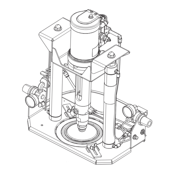
Page 7: Component Identification
Component Identification Component Identification 27(A) 30(B) 27(B) 30(A) . 1: System Components Key: Wiper Plate Assembly 34 Base Pump 36 Ram Director Valve Bleed-Type Mater Air Valve 37 Air Assist Valve Connector 18 Air Assist Valve (Push Button 39 Clamp Wing Screws 24 Clamps 57 Air Inlet for Main Air Line 25 Pump Bleeder Valve... -
Page 8: Installation
(X) located on the ram base (Z). Install a 1.5 tem’s requirements. Contact your Graco distributor for (12 awg) minimum ground wire (Y) and secure with assistance in designing a system to suit your needs. -
Page 9: Connect And Disconnect Tubes
Installation Pump Components and 4. Set the ram air regulator (27B) to zero. Set the ram director valve switch (36) to the down position. As Accessories the ram unit slowly falls, guide the pump intake housing (111) into the wiper plate (P). 5. -
Page 10: Operation
Operation Operation Pressure Relief Procedure 5. Unlock the dispensing device trigger. 6. Hold a metal part of the gun/valve firmly to the side Follow the Pressure Relief Procedure whenever of a grounded pail and trigger the dispensing device you see this symbol. to relieve pressure. -
Page 11: Flush The System
Operation Flush the System Start and Adjust the Ram To reduce the risk of serious injury and damage to equipment, do not shut off the air supply to the ram when the ram is raised. Doing so will cause the pump to fall uncontrolled to the bottom. -
Page 12: Start And Adjust The Pump
Operation 5. Loosen the wiper plate bleed valve (303) enough to 6. Adjust the air motor regulator until the pump starts. allow air trapped under the wiper plate to escape. With your hands away from the lip of the can and Pressure Gauge the wiper plate, set the ram director valve switch (36) to the down position and lower the ram until the... -
Page 13: Prime The Pump And Pump Fluid
Operation Prime the Pump and Pump Fluid NOTE: Always use the lowest possible fluid pressure to bleed air out of the pump. 1. Be sure the pump air regulator (27A) is closed. Then set the ram air regulator (27B) to be about 22 psi (150 kPa, 1.5 bar). -
Page 14: Shutdown And Care Of The Pump
Operation 7. Loosen the clamps (24) and remove the empty can. 2. Set the ram director valve to the down position. Set the full can on the ram base and position it under the wiper plate. If the can has a welded seam, position it with the seam facing the rear of the pump to avoid injury due to splat- tering fluid if the can leaks at the seam. -
Page 15: Troubleshooting
Troubleshooting Troubleshooting Before servicing this equipment always make sure to Check all possible problems and solutions before disas- follow the Pressure Relief Procedure on page 10. sembling the pump. Problem Cause Solution Pump fails to operate. Restricted line or inadequate air Clear;... -
Page 16: Service
Refer to those for service. damage. Reassemble as explained on this page. NOTE: Repair Kit 223894 is available to repair 235871, and Repair Kit 25C844 is available to repair 25C837. Reassembly Parts included in these kits are marked with a symbol †... - Page 17 Service 5. Apply lubricant to the threads of the screw (145). Hold the fluid piston (106) steady by inserting a small screwdriver or punch into the 4mm diameter hole (A). Install the priming piston (115) onto the end of the priming piston rod (110), using the screw (145) and lockwasher (135).
- Page 18 Service Torque to 298-314 in-lb (35-37 N•m). Torque to 14-20 in-lb (1.7-2.3 N•m). Lips must face down. Lubricate Apply thread lubricant. . 8: Pump Service Components 308302P...
-
Page 19: 235871, Series D Parts
235871, Series D Parts 235871, Series D Parts Detail C Detail A Detail B See Detail A above. See Detail B above See Detail C above Part of item 36. part of item 18. . 9: DynaMite 190 Extruder Assembly Parts without Air Tubing Part Description Quantity... - Page 20 235871, Series D Parts Part Description Quantity 223730 VALVE, assy 112189 FITTING, y 110318 REGULATOR, air, 1/4 in. npt 166866 FITTING, elbow, street 108190 GAUGE, pressure, air 100839 FITTING, elbow, street 110209 NUT, regulator 188852 BRACKET 236062 BASE, elevator 110859 VALVE, air, manual 110932 CONNECTOR, male...
- Page 21 235871, Series D Parts . 10: DynaMite 190 Extruder Assembly Air Tubing Parts Ref Part Description Quantity 186532 TUBE, air 186533 TUBE, air 186534 TUBE, air 188963 TUBE, air 188964 TUBE, air 188965 TUBE, air 188966 TUBE, air 188967 TUBE, air 188968 TUBE, air 308302P...
-
Page 22: 25C837, Series A Parts
25C837, Series A Parts 25C837, Series A Parts Detail C Detail A 39 13 Detail B See Detail A above. See Detail B above See Detail C above Part of item 36. part of item 18. . 11: DynaMite 190 Extruder Assembly Parts without Air Tubing... - Page 23 25C837, Series A Parts Part Description Quantity 223730 VALVE, assy 112189 FITTING, y 110318 REGULATOR, air, 1/4 in. npt 166866 FITTING, elbow, street 108190 GAUGE, pressure, air 100839 FITTING, elbow, street 110209 NUT, regulator 17S475 BRACKET 236062 BASE, elevator 110859...
-
Page 24: 235870, Series D Parts
235870, Series D Parts 235870, Series D Parts . 12: Pump Assembly Parts 308302P... - Page 25 235870, Series D Parts Part Description Quantity 187579 PISTON, fluid 235838 CUP, wet 187578 HOUSING, fluid 187586 ROD, plunger 186283 VALVE, intake 186285 STOP 186296† VALVE, fluid 187759 PLUNGER, priming piston 110893 PIN, spring 111640 WASHER, lock, internal 112120 PIN, spring 111639 SCREW, cap, hex hd 110966†...
-
Page 26: 25C829, Series A Parts
25C829, Series A Parts 25C829, Series A Parts Torque to 298-314 in-lb (35-37 N•m). Torque to 14-20 in-lb (1.7-2.3 N•m). Lips must face down. Lubricate Apply thread lubricant. . 13: Pump Service Components 308302P... - Page 27 25C829, Series A Parts Part Description Quantity 17R326 PISTON, fluid 235838 CUP, wet 187578 HOUSING, fluid 17R327 ROD, plunger 186283 VALVE, intake 17R329 STOP 186296† VALVE, fluid 17R330 PLUNGER, priming piston 110893 PIN, spring 111640 WASHER, lock, internal 112120 PIN, spring 111639 SCREW, cap, hex hd 110966†...
-
Page 28: Accessory Can Opener
(not supplied with unit) For use with containers that have a lip at the top that needs to be removed. Graco Kit 111002 is available and can be purchased separately. Wiper Plate Parts Part No. 25C843 1 Gallon (3.79 liter) Size NOTE: The wiper plate is not supplied with the pump and must be ordered separately. - Page 29 Wiper Plate Parts Part No. 224923 1 Quart (.95 liter) Size Includes items 301-312 Part Description Quantity 187596 PLATE, inductor 111639 SCREW, cap, hex hd 223746 VALVE, bleed 187738 RING, sst. 187740 WIPER, 111638 SCREW, cap, hex hd 111637 WASHER, lock 187741 RING, backup 110954†...
-
Page 30: Dimensions
Dimensions Dimensions Raised: 28.75 in. (730.1 mm) Lowered: 19.75 in. (501.5 mm) Fluid Outlet 1/4 npt(f) Air Inlet 1/4 npt(f) Width of Base Only: 14.0 in. (355.6 mm.) Width Including 8.25 in. (209.6 mm) Air Regulators: 17.0 in. (431.8 mm) . -
Page 31: Technical Data
Technical Data Technical Data DynaMite 190 Extruder Metric Maximum fluid output pressure 1200 psi 8.3 MPa, 83 bar Air input pressure 35-100 psi 243-700 KPa, 2.4-7.0 bar Maximum fluid viscosity 600,000 cps Volume per stroke 0.17 oz 5.0 cc Recommended pump speed for continuous 40 cycles per minutes (cpm) operation Maximum recommended pump speed... -
Page 32: Technical Data - Fluid Flow Chart
Technical Data Technical Data - Fluid Flow Chart CYCLES PER MINUTE A = 100 PSI (0.7 MPa, 7 bar) 1000 B = 70 PSI (0.5 MPa, 5 bar) C = 40 PSI (0.3 MPa, 3 bar) = AIR FLOW = FLUID FLOW MATERIAL VISCOSITY (150,000 CENTIPOISE) 200 250 MATERIAL FLOW RATE (CC/MIN) - Page 33 Technical Data 308302P...
-
Page 34: Graco Standard Warranty
With the exception of any special, extended, or limited warranty published by Graco, Graco will, for a period of twelve months from the date of sale, repair or replace any part of the equipment determined by Graco to be defective.