Table of Contents
Advertisement
Quick Links
Instructions – Parts List
Parts
ACETAL, POLYPROPYLENE, AND KYNARR
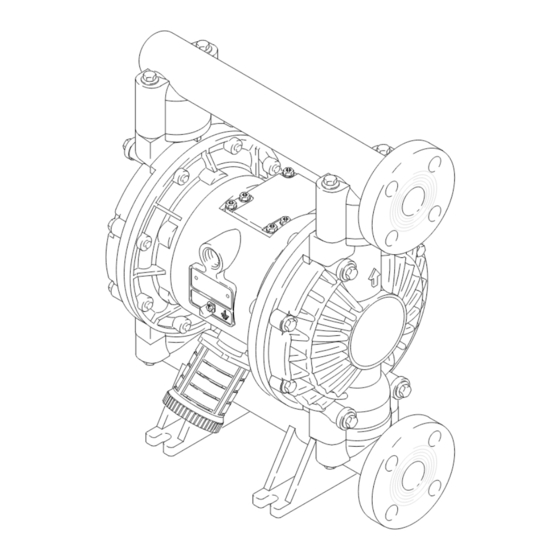
Huskyt1040 Air-Operated
Diaphragm Pumps
Acetal Model Shown
120 psi (0.8 MPa, 8 bar) Maximum Fluid Working Pressure
120 psi (0.8 MPa, 8 bar) Maximum Air Input Pressure
*Model No. D71
*Model No. D81
*Model No. D72
*Model No. D82
*Model No. D75
*Model No. D85
*Model No. DR2
*Model No. DS2
*Model No. DR5
*Model No. DS5
*NOTE: Refer to the Pump Matrix on page 24 to
determine the Model No. of your pump.
NOTE: Plus Models include stainless steel
center sections.
US and Foreign Patents Pending
Read warnings and instructions.
See page 2 for table of contents
GRACO INC. P.O. BOX 1441 MINNEAPOLIS, MN 55440-1441
Copyright 1994, Graco Inc. is registered to I.S. EN ISO 9001
Acetal Pumps
Acetal Pumps, Remote
Polypropylene Pumps
Polypropylene Pumps, Remote
Kynarr Pumps
Kynarr Pumps, Remote
Polypropylene Plus
Pumps
Polypropylene Plus
Pumps, Remote
Kynarr Plus Pumps
Kynarr Plus
Pumps, Remote
308443S
04155B
Advertisement
Table of Contents

Related Manuals for Graco D71


Summary of Contents for Graco D71
- Page 1 NOTE: Plus Models include stainless steel center sections. US and Foreign Patents Pending Read warnings and instructions. See page 2 for table of contents 04155B GRACO INC. P.O. BOX 1441 MINNEAPOLIS, MN 55440-1441 Copyright 1994, Graco Inc. is registered to I.S. EN ISO 9001...
-
Page 2: Table Of Contents
D Read all instruction manuals, tags, and labels before operating the equipment. D Use the equipment only for its intended purpose. If you are not sure, call your Graco distributor. D Do not alter or modify this equipment. Use only genuine Graco parts and accessories. - Page 3 WARNING TOXIC FLUID HAZARD Hazardous fluid or toxic fumes can cause serious injury or death if splashed in the eyes or on the skin, inhaled, or swallowed. D Know the specific hazards of the fluid you are using. D Store hazardous fluid in an approved container. Dispose of hazardous fluid according to all local, state and national guidelines.
-
Page 4: Installation
Retorque the fluid cover screws first, then the manifold in planning a system to suit your needs. screws. This keeps the manifolds from interfering with D Always use Genuine Graco Parts and Accessories. tightening the fluid covers. See the Service section for torque specifications. - Page 5 This pump must be grounded. Before mable fluid containers during filling. This is only a operating the pump, ground the system guide; contact your Graco distributor for assistance in as explained below. Also read the sec- grounding your system. tion FIRE AND EXPLOSION HAZARD Ground all of this equipment: on page 3.
- Page 6 Installation Air Line b. Locate one bleed-type master air valve (B) WARNING close to the pump and use it to relieve trapped air. See the WARNING at left. Locate the other A bleed-type master air valve (B) is required in master air valve (E) upstream from all air line your system to relieve air trapped between this accessories and use it to isolate them during...
- Page 7 1. Use grounded fluid hoses (L). The pump fluid 3. Connect remaining ends of tubes to external air outlet (S) is a 1” raised face flange. Refer to signal, such as Graco’s Cycleflo (P/N 195264) or Flange Connections on page 8. Cycleflo II (P/N195265) controllers.
- Page 8 Installation Flange Connections The fluid inlet and outlet ports are 1” raised face 1. Place a lockwasher and a flat washer on each bolt. flanges. Connect 1” flanged plastic pipe to the pump Refer to Fig. 3. as follows. You will need: D Torque wrench 2.
- Page 9 Installation Changing the Orientation of the Fluid Inlet Fluid Pressure Relief Valve and Outlet Ports The pump is shipped with the fluid inlet (R) and outlet CAUTION (S) ports facing the same direction. See Fig. 4. To change the orientation of the inlet and/or outlet port: Some systems may require installation of a pres- sure relief valve at the pump outlet to prevent 1.
- Page 10 Installation Air Exhaust Ventilation The air exhaust port is 3/4 npt(f). Do not restrict the air WARNING exhaust port. Excessive exhaust restriction can cause erratic pump operation. FIRE AND EXPLOSION HAZARD Be sure to read FIRE OR EXPLOSION To provide a remote exhaust: HAZARD and TOXIC FLUID HAZARD on page 3, before operating this pump.
-
Page 11: Operation
Operation Pressure Relief Procedure 1. Be sure the pump is properly grounded. Refer to Grounding on page 5. WARNING 2. Check all fittings to be sure they are tight. Be sure PRESSURIZED EQUIPMENT HAZARD to use a compatible liquid thread sealant on all The equipment stays pressurized until pressure is male threads. - Page 12 Operation Operation of Remote Piloted Pumps NOTE: Leaving air pressure applied to the air motor for extended periods when the pump is not running may shorten the diaphragm life. Using a 3–way solenoid 1. Follow preceding steps 1 through 7 of Starting valve to automatically relieve the pressure on the air and Adjusting Pump.
-
Page 13: Maintenance
Maintenance Lubrication Tightening Threaded Connections The air valve is designed to operate unlubricated, Before each use, check all hoses for wear or damage, however if lubrication is desired, every 500 hours of and replace as necessary. Check to be sure all operation (or monthly) remove the hose from the pump threaded connections are tight and leak-free. -
Page 14: Troubleshooting
Troubleshooting 1. Relieve the pressure before checking or servicing WARNING the equipment. To reduce the risk of serious injury whenever you are instructed to relieve pressure, always follow the 2. Check all possible problems and causes before Pressure Relief Procedure on page 11. disassembling the pump. - Page 15 Troubleshooting PROBLEM CAUSE SOLUTION Fluid in exhaust air. Diaphragm ruptured. Replace. See pages 19 to 21. Loose fluid side plate (105). Tighten or replace (pages 19 to 21). Pump exhausts excessive air at Worn air valve block (7), o-ring (6), Repair or replace.
-
Page 16: Repairing The Air Valve
Service Repairing the Air Valve 7. Clean all parts and inspect for wear or damage. Replace as needed. Reassemble as explained on page 17. Tools Required D Torque wrench D Torx (T20) screwdriver or 7 mm (9/32”) socket wrench D Needle-nose pliers D O-ring pick D Lithium base grease NOTE: Air Valve Repair Kit 236273 is available. - Page 17 Service Reassembly Insert narrow end first. 1. If you removed the bearings (12, 15), install new Grease. ones as explained on page 22. Reassemble the fluid section. Install with lips facing narrow end of piston (11). Insert wide end first. 2.
-
Page 18: Ball Check Valve Repair
Service Ball Check Valve Repair Reassembly 1. Clean all parts and inspect for wear or damage. Tools Required Replace parts as needed. D Torque wrench 2. Reassemble in the reverse order, following all notes in Fig. 11. Assemble the ball checks exactly D 10 mm socket wrench as shown. -
Page 19: Diaphragm Repair
Service Diaphragm Repair Disassembly NOTE: A Fluid Section Repair Kit is available. Refer to page 25 to order the correct kit for your pump. Parts Tools Required included in the kit are marked with an asterisk, for example (401*). Use all the parts in the kit for the best D Torque wrench results. - Page 20 Service 4. Unscrew one outer plate (105) from the diaphragm Reassembly shaft (24). Remove one diaphragm (401), and the 1. Grease the shaft u-cup packings (402*) and install inner plate (104). See Fig. 13. them so the lips face out of the housing (1). See Fig.
- Page 21 Service 402* 403* 401* 04236 02637 Cutaway View, with Diaphragms in Place Cutaway View, with Diaphragms Removed 401* 403* Lips face out of housing (1). Rounded side faces diaphragm (401). Air Side must face center housing (1). Grease. Apply medium-strength (blue) LoctiteR or equiva- lent.
-
Page 22: Bearing And Air Gasket Removal
Service Bearing and Air Gasket Removal Tools Required Reassembly D Torque wrench 1. If removed, install the shaft u-cup packings (402*) so the lips face out of the housing (1). D 10 mm socket wrench D Bearing puller 2. The bearings (19, 12, and 15) are tapered and can only be installed one way. - Page 23 Service Insert bearings tapered end first. Press-fit bearings flush with surface of center housing (1). Apply medium-strength (blue) LoctiteR or equivalent. Torque to 130 to 150 in-lb (14.7 to 16.9 N-m). 04158 Detail of Air Valve Bearings 02639B Fig. 14 308443...
-
Page 24: Pump Matrix
Pump Matrix Husky 1040 Acetal, Polypropylene, and Kynar Pumps, Series A Your Model No. is marked on the pump’s serial plate. To determine the Model No. of your pump from the following matrix, select the six digits which describe your pump, working from left to right. The first digit is always D, designating Husky diaphragm pumps. -
Page 25: Repair Kit Matrix
Repair Kit Matrix For Husky 1040 Acetal, Polypropylene, and Kynar Pumps, Series A Repair Kits may be ordered separately. To repair the air valve, order Part No. 236273 (see page 26). Parts included in the Air Valve Repair Kit are marked with a symbol in the parts list, for example (3). To repair your pump, select the six digits which describe your pump from the following matrix, working from left to right. -
Page 26: Parts
Parts *402 401* 301* 403* 201* 202* 113* *301 *201 202* Not used on some models. * These parts are included in the Pump Repair Kit, which may be purchased separately. Refer to the Repair Kit Matrix on page 25 to determine the correct kit for your pump. { These parts are included in Air Valve Repair Kit 236273, which may be purchased separately. - Page 27 Parts Air Motor Parts List (Matrix Column 2) Air Motor Parts List (Matrix Column 2) Ref. Ref. Digit Part No. Description Digit Part No. Description 188838 HOUSING, center; Same as 7 with the following exceptions aluminum 195921 HOUSING, center; 188854 COVER, air valve;...
- Page 28 Fluid Section Parts List (Matrix Column 3) Fluid Section Parts List (Matrix Column 3) Ref. Ref. Digit Part No. Description Digit Part No. Description 189377 COVER, fluid; acetal 189378 COVER, fluid; KynarR 189371 MANIFOLD, inlet; acetal 189372 MANIFOLD, inlet; Ky- narR 189374 MANIFOLD, outlet;...
- Page 29 Parts Seat Parts List (Matrix Column 4) Ref. Ref. Digit Part No. Description Digit Part No. Description 201* 188604 SEAT; acetal 401* 188606 DIAPHRAGM, backup; HytrelR 202* 109205 O-RING; PTFE 402* 112181 PACKING, u-cup; nitrile 201* 188707 SEAT; 316 stainless steel 403* 188605 DIAPHRAGM;...
-
Page 30: Dimensional Drawings
Dimensional Drawings 13.5 in. (343 mm) 7.57 in. (192 mm) FRONT VIEW 1/2 npt(f) Air Inlet 16.88 in. 12.25 in. (4.28.5 mm) (311 mm) 14.75 in. (374.5 mm) 9.8 in. (249 mm) 2.5 in. (63.5 mm) (ANSI Flange) Fluid Outlet .375 in. -
Page 31: Technical Data And Performance Chart
Technical Data Maximum fluid working pressure ....120 psi Wetted parts ..Vary by Model. See pages 27 and 29 (0.8 MPa, 8 bar) Non-wetted external parts aluminum, 302, 316 stainless steel Air pressure operating range... - Page 32 Performance Chart Test Conditions: Pump tested in water with inlet submerged. Fluid Pressure Curves (0.84, 8.4) A at 120 psi (0.7 MPa, 7 bar) air pressure B at 100 psi (0.7 MPa, 7 bar) air pressure (0.7, 7) C at 70 psi (0.48 MPa, 4.8 bar) air pressure D at 40 psi (0.28 MPa, 2.8 bar) air pressure (0.55, 5.5) To find Fluid Outlet Pressure...
- Page 33 Notes 308443...
-
Page 34: Graco Standard Warranty
Graco distributor to the original purchaser for use. With the exception of any special, extended, or limited warranty published by Graco, Graco will, for a period of five years from the date of sale, repair or replace any part of the equipment determined by Graco to be defective.