Table of Contents
Advertisement
Quick Links
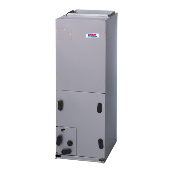
F5M4
115V FAN COIL UNITS
SIZES 018 TO 060
NOTE: Read the entire instruction manual before starting the
installation.
Table of Contents
Safety Considerations . . . . . . . . . . . . . . . . . . . . . . . . . . . . . . . . . . . . . 1
Introduction. . . . . . . . . . . . . . . . . . . . . . . . . . . . . . . . . . . . . . . . . . . . . 1
Electric Heat . . . . . . . . . . . . . . . . . . . . . . . . . . . . . . . . . . . . . . . . . . . . 2
Installation . . . . . . . . . . . . . . . . . . . . . . . . . . . . . . . . . . . . . . . . . . . . . 2
Check Equipment. . . . . . . . . . . . . . . . . . . . . . . . . . . . . . . . . . . . . . 2
Mount Unit . . . . . . . . . . . . . . . . . . . . . . . . . . . . . . . . . . . . . . . . . . . 2
Upflow Installation . . . . . . . . . . . . . . . . . . . . . . . . . . . . . . . . . . . . 2
Downflow Installation . . . . . . . . . . . . . . . . . . . . . . . . . . . . . . . . . . 2
Horizontal Installation . . . . . . . . . . . . . . . . . . . . . . . . . . . . . . . . . . 2
Air Ducts. . . . . . . . . . . . . . . . . . . . . . . . . . . . . . . . . . . . . . . . . . . . . . . 6
Ductwork Acoustical Treatment . . . . . . . . . . . . . . . . . . . . . . . . . . 6
Electrical Connections . . . . . . . . . . . . . . . . . . . . . . . . . . . . . . . . . . . . 6
Line Voltage Connections . . . . . . . . . . . . . . . . . . . . . . . . . . . . . . . 6
24V Control System. . . . . . . . . . . . . . . . . . . . . . . . . . . . . . . . . . . . 6
Ground Connections . . . . . . . . . . . . . . . . . . . . . . . . . . . . . . . . . . . 7
Minimum CFM and Motor Speed Selection . . . . . . . . . . . . . . . . . 7
Table 1 - Fan Speed Selection. . . . . . . . . . . . . . . . . . . . . . . . . . . . 8
Refrigerant Tubing Connection and Evacuation . . . . . . . . . . . . . . . . 8
Refrigerant Flow-Control Device . . . . . . . . . . . . . . . . . . . . . . . . . . . . 8
Condensate Drains . . . . . . . . . . . . . . . . . . . . . . . . . . . . . . . . . . . . . . . 9
Accessories . . . . . . . . . . . . . . . . . . . . . . . . . . . . . . . . . . . . . . . . . . . . 10
Humidifier . . . . . . . . . . . . . . . . . . . . . . . . . . . . . . . . . . . . . . . . . . 10
Sequence of Operation . . . . . . . . . . . . . . . . . . . . . . . . . . . . . . . . . . . 10
Continuous Fan . . . . . . . . . . . . . . . . . . . . . . . . . . . . . . . . . . . . . . 10
Cooling Mode . . . . . . . . . . . . . . . . . . . . . . . . . . . . . . . . . . . . . . . 11
Start-up Procedures. . . . . . . . . . . . . . . . . . . . . . . . . . . . . . . . . . . . . . 11
Care and Maintenance . . . . . . . . . . . . . . . . . . . . . . . . . . . . . . . . . . . 11
Table 2 - Airflow Performance (CFM) Wet . . . . . . . . . . . . . . . . 12
Table 3 - Airflow Performance (CFM) Dry . . . . . . . . . . . . . . . . 13
Safety Considerations
Improper installation, adjustment, alteration, service, maintenance, or
use can cause explosion, fire, electrical shock, or other conditions which
may cause death, personal injury or property damage. Consult a
qualified installer, service agency, or your distributor or branch for
information or assistance. The qualified installer or agency must use
factory-authorized kits or accessories when modifying this product.
Refer to the individual instructions packaged with kits or accessories
when installing.
Follow all safety codes. Wear safety glasses, protective clothing and
work gloves. Have a fire extinguisher available. Read these instructions
thoroughly and follow all warnings or cautions included in literature and
attached to the unit. Consult local building codes and the current editions
of the National Electrical Code (NEC) NFPA 70.
In Canada, refer to the current editions of the Canadian Electrical Code
CSA C22.1.
Recognize safety information. This is the safety-alert symbol
you see this symbol on the unit and in instruction manuals, be alert to the
potential for personal injury.
Understand the signal words DANGER, WARNING, and CAUTION.
These words are used with the safety-alert symbol. DANGER identifies
Installation Instructions
. When
the most serious hazards which will result in severe personal injury or
death. WARNING signifies hazards which could result in personal
injury or death. CAUTION is used to identify unsafe practices which
may result in minor personal injury or product and property damage.
NOTE is used to highlight suggestions which will result in enhanced
installation, reliability, or operation.
WARNING
!
PERSONAL INJURY / PROPERTY DAMAGE HAZARD
Failure to follow this warning could result in property damage, personal
injury, or death.
For continued performance, reliability, and safety, the only approved
accessories and replacement parts are those specified by the equipment
manufacturer. The use of non-manufacturer approved parts and
accessories could invalidate the equipment limited warranty and result
in fire risk, equipment malfunction, and failure. Please review
manufacturer's instructions and replacement part catalogs available
from your equipment supplier.
WARNING
!
ELECTRICAL OPERATION HAZARD
Failure to maintain proper clearances could result in personal injury or
death.
Before installing or servicing unit, always turn off all power to unit.
There may be more than 1 disconnect switch. Turn off accessory heater
power if applicable.
!
CUT HAZARD
Failure to follow this caution may result in personal injury.
Sheet metal parts may have sharp edges or burrs. Use care and wear
appropriate protective clothing, safety glasses and gloves when
handling parts.
!
HOT TUBE WARNING
Failure to follow this caution could result in personal injury.
Refrigerant lines can reach or exceed 130 °F (54 °C). Avoid contact
with the vapor header or vapor line, especially in Heating Mode.
Introduction
These R-410A Fan Coils designed for installation flexibility. The units
leave the factory compliant with low leak requirements of less than 2%
cabinet leakage rate at 0.5 inches W.C. and 1.4% cabinet leakage rate at
0.5 inches W.C. when tested in accordance with ASHRAE 193 standard.
CAUTION
CAUTION
Advertisement
Table of Contents

Related Manuals for Carrier F5M4


Summary of Contents for Carrier F5M4
-
Page 1: Table Of Contents
F5M4 115V FAN COIL UNITS SIZES 018 TO 060 Installation Instructions NOTE: Read the entire instruction manual before starting the the most serious hazards which will result in severe personal injury or death. WARNING signifies hazards which could result in personal installation. -
Page 2: Electric Heat
F5M4: Installation Instructions All these fan coils use a multi-tap ECM motor for efficiency. The units condensate pan to be installed under the entire unit. Some localities may have be designed for upflow, downflow (kit required), and horizontal allow as an alternative, the running of a separate, secondary condensate orientations, including manufactured and mobile home applications. - Page 3 F5M4: Installation Instructions POWER ENTRY FIELD SUPPLIED OPTIONS SUPPLY DUCT LOW VOLT ENTRY OPTIONS 018 - 048 21" (533 mm) FRONT SERVICE 060 - 060 24" (610mm) CLEARANCE UNIT 12" (305 mm) 018, 024 025 - 030 17" (432 mm) A COIL 19"...
- Page 4 F5M4: Installation Instructions A-COIL HORIZONTAL LEFT PRIMARY SECONDARY DRAIN FIELD DRAIN SUPPLIED HANGING STRAPS 018-048 21" (533 mm) 060-060 24" (610 mm) FRONT SERVICE CLEARANCE UNIT (FULL FACE OF UNIT) LOW VOLT ENTRY OPTIONS 1.75" (44 mm) FILTER ACCESS CLEARANCE...
- Page 5 F5M4: Installation Instructions REFRIGERANT AIR SEAL CONNECTIONS ASSEMBLY HORIZONTAL RIGHT APPLICATION COIL SUPPORT RAIL COIL BRACKET DRAIN PAN SUPPORT BRACKET COIL SUPPORT RAIL COIL BRACKET HORIZONTAL DRAIN PAN PRIMARY DRAIN HORIZONTAL RIGHT SECONDARY DRAIN HORIZONTAL RIGHT A00071A Fig. 6 – Conversion for Horizontal Right Applications - A-Coil...
-
Page 6: Air Ducts
F5M4: Installation Instructions Air Ducts WARNING Connect supply-air duct over the outside of ¾" (19 mm) flanges provided on supply-air opening. Secure duct to flange, using proper ELECTRICAL SHOCK HAZARD fasteners for type of duct used, and seal duct-to-unit joint. If return-air Failure to follow this warning could result in personal injury or death. -
Page 7: Ground Connections
F5M4: Installation Instructions A94059A Fig. 11 – Wiring Layout 1-Stage HP Unit A03088A Fig. 13 – Wiring Layout 2-Stage HP Unit Transformer Information The transformer is factory wired for 115V operation. Ground Connections NOTE: Use UL listed conduit and conduit connectors for connecting supply wire(s) to unit to obtain proper grounding. -
Page 8: Refrigerant Tubing Connection And Evacuation
F5M4: Installation Instructions CAUTION PRODUCT DAMAGE HAZARD Failure to follow this caution may result in product or property damage. A brazing shield MUST be used when tubing sets are being brazed to 1 2 3 4 5 the unit connections to prevent damage to the unit surface and condensate pan fitting caps. -
Page 9: Condensate Drains
F5M4: Installation Instructions Assembly NOTE: When connecting condensate drain lines, avoid blocking filter access panel, thus preventing filter removal. After connection, prime 1. Mount the TXV bracket and TXV with the 2 screws removed both primary and secondary condensate traps. -
Page 10: Accessories
F5M4: Installation Instructions Install traps in the condensate lines as close to the coil as possible. (Fig. 18). Make sure that the outlet of each trap is below its connection to the condensate pan to prevent condensate from overflowing the drain pan. -
Page 11: Cooling Mode
F5M4: Installation Instructions your dealer for maintenance. The only consumer service recommended or required is filter replacement or cleaning on a monthly basis. NOTE: Servicing the blower assembly requires the removal of two screws that attach the blower housing to the fan deck. It is not necessary to reinstall of these screws after service. - Page 12 F5M4: Installation Instructions Table 2 – Airflow Performance (CFM) Wet External Static (in. wc) Blower (Size) Speed Tap 5 Tap 4 1-1/2 Tap 3 (018) Tap 2 Tap 1 Tap 5 1021 1003 Tap 4 Tap 3 (024) Tap 2...
- Page 13 Return static pressure must be less than 0.40 in. wc. Horizontal applications of 042 - 060 sizes must have supply static greater than 0.20 in. wc. Airflow above 400 cfm/ton on 048-060 size could result in condensate blowing off coil or splashing out of drain pan. © 2023 Carrier. All rights reserved. Edition Date: 8/23...