Table of Contents
Advertisement
40MBAA
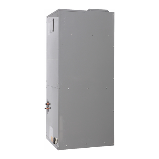
Fig. 1 - Air Handler
NOTE: Read the entire instruction manual before starting the
installation.
TABLE OF CONTENTS
SAFETY CONSIDERATIONS ....................................................... 1
INTRODUCTION............................................................................ 2
HEATER PACKAGES .................................................................... 2
DIMENSIONS ................................................................................. 3
INSTALLATION REQUIREMENTS............................................. 4
INSTALLATION............................................................................. 5
Step 1 - Check Equipment................................................................ 5
Step 2 - Mount Unit.......................................................................... 5
Step 3 - Mount Electric Heater (Optional) ....................................... 8
Step 4 - Installing Ductwork ............................................................ 11
Step 5 - Condensate Drains .............................................................. 12
Step 6 - Refrigerant Piping............................................................... 13
Step 7 - Evacuate Coil and Tubing System...................................... 15
Step 8 - Electrical Connections ........................................................ 16
INDOOR UNIT WIRING................................................................ 16
WIRING REQUIREMENTS ........................................................... 17
ELECTRICAL DATA ..................................................................... 18
CONNECTION DIAGRAMS ......................................................... 18
Step 9 - Third Party Thermostat Installation.................................... 19
Step 10 - Setting Static Pressure and Airflow.................................. 20
TEST RUN....................................................................................... 25
SYSTEM CHECKS ......................................................................... 25
START-UP PROCEDURES............................................................ 25
TROUBLESHOOTING................................................................... 26
Installation Instructions
PAGE
Specifications subject to change without notice.
Air Handler Unit Ductless System
SAFETY CONSIDERATIONS
Improper installation, adjustment, alteration, service, maintenance, or
use can cause explosion, fire, electrical shock, or other conditions
which may cause death, personal injury or property damage. Consult a
qualified installer, service agency, or your distributor or branch for
information or assistance. The qualified installer or agency must use
factory-authorized kits or accessories when modifying this product.
Refer to the individual instructions packaged with kits or accessories
when installing.
Follow all safety codes. Wear safety glasses, protective clothing and
work gloves. Have a fire extinguisher available. Read these
instructions thoroughly and follow all warnings or cautions included
in the literature and attached to the unit. Consult local building codes
and the current editions of the National Electrical Code (NEC) NFPA
70.
In Canada, refer to the current editions of the Canadian
Electrical Code CSA C22.1. Recognize safety information.
This is the safety-alert symbol
unit and in instruction manuals, be alert to the potential for personal
injury. Understand the signal words DANGER, WARNING, and
CAUTION. These words are used with the safety-alert symbol.
DANGER identifies the most serious hazards which will result in
severe personal injury or death. WARNING signifies hazards which
could result in personal injury or death. CAUTION is used to identify
unsafe practices which may result in minor personal injury or product
and property damage. NOTE is used to highlight suggestions which
will result in enhanced installation, reliability, or operation.
WARNING
ELECTRICAL OPERATION HAZARD
Failure to follow this warning could result in personal injury or
death.
Before installing or servicing the unit, always turn off all power to
the unit. There may be more than one disconnect switch. Turn off
accessory heater power if applicable. Lock out and tag switch with
a suitable warning label.
CAUTION
CUT HAZARD
Failure to follow this caution may result in personal injury. Sheet
metal parts may have sharp edges or burrs. Use care and wear
appropriate protective clothing and gloves when handling parts.
Sizes 24 to 48
. When you see this symbol on the
Advertisement
Table of Contents

Related Manuals for Carrier 40MBAAQ24XA3


Summary of Contents for Carrier 40MBAAQ24XA3
-
Page 1: Table Of Contents
40MBAA Air Handler Unit Ductless System Sizes 24 to 48 Installation Instructions SAFETY CONSIDERATIONS Improper installation, adjustment, alteration, service, maintenance, or use can cause explosion, fire, electrical shock, or other conditions which may cause death, personal injury or property damage. Consult a qualified installer, service agency, or your distributor or branch for information or assistance. -
Page 2: Introduction
Fig. 2 — Air Regulator Table 1 — Indoor Unit Model Numbers KBTUH V-PH-HZ ID MODEL NO. Coil Compartment 40MBAAQ24XA3 (Access Panel Removed) 208/230-1-60 40MBAAQ36XA3 Upflow Drain Pan 40MBAAQ48XA3 CAUTION Horizontal Drain Pan This unit is NOT equipped with a single point electrical Fig. -
Page 3: Dimensions
DIMENSIONS Top View D DUCT 18.2 [462] 2.2 [57] Front View Rear Side View Right Side View D 18.2 [462] E 10.3 [262] Air Outlet 1.7 [44] Blower Coil Filter Air Inlet 3.0 [75] B DEPTH 21.1 [535] 1.2 [30] 2.2 [55] C WIDTH 19.7 [501] Bottom View... -
Page 4: Installation Requirements
INSTALLATION REQUIREMENTS WARNING Review the following information before installing the unit: • Install the unit in a location within the room that allows uniform airflow in all directions. PRODUCT INSTALLATION • Do not install the indoor units near a direct source of heat such as •... -
Page 5: Installation
INSTALLATION Step 1 - Check Equipment Step 2 - Mount Unit Unpack the unit and move to the final location. Remove the carton, The unit can stand or lie on the floor, or hang from a ceiling or a wall. taking care not to damage the unit. - Page 6 A. Upflow or Horizontal-Right Installation B. Downflow or Horizontal-Left Installation The units can be installed in a vertical Upflow or horizontal (right) For the Horizontal Left installation and the Vertical Downflow configuration. installation, the direction of the evaporator should be changed and the drain pan should be removed first.
- Page 7 4. Remove the drain pan support bracket and the locking clip. 8. Reinstall the evaporator and drain pan assembly. Remove the filter plate Clip Bracket Fig. 15 — Reinstall the evaporator and drain pan Fig. 12 — Remove the Support Bracket and Clip assembly 5.
-
Page 8: Step 3 - Mount Electric Heater (Optional)
Step 3 - Mount Electric Heater (Optional) 11. Reinstall the evaporator cover. Table 5 — Accessories NAME SHAPE QUANTITY Owner’s and Installation Manual Seal Screw Fig. 18 — Reinstall the Evaporator Cover 12. Reinstall the filter and the filter plate. Resilient Cap Electric Auxiliary Heating Wiring... - Page 9 ELECTRIC AUXILIARY HEAT MODULE 5. Use the 3 screws (6 screws for 15K or 20K) removed previously and fasten the outer cover of the module into the access hole. INSTALLATION AND WIRING 1. Remove the six screws securing the upper cover plate and the chassis.
- Page 10 9. Insert the white plug of the electric heating control line into the electric control box through the reserved crossing hole and insert into the corresponding white plug in the electronic control box. Fig. 31 — Choose the power cord installation location 12.
-
Page 11: Step 4 - Installing Ductwork
Step 4 - Installing Ductwork 14. Fasten the resilient cap and seal on the upper cover plate with 4 screws. Connect the supply-air duct over the outside of the 3/4in (19 mm) flanges provided on the supply-air opening. Secure the duct to the flange, using proper fasteners for the type of duct used, and seal duct- to-unit joint. -
Page 12: Step 5 - Condensate Drains
Step 5 - Condensate Drains The drainpipe is used to drain water away from the unit. Improper installation may cause unit and property damage. CAUTION • Insulate all piping to prevent condensation, which could lead to ≥ water damage. Check the local codes. •... -
Page 13: Step 6 - Refrigerant Piping
Step 6 - Refrigerant Piping IMPORTANT: 3. Cut tubing to correct length. Both refrigerant lines must be insulated separately. When preparing refrigerant pipes, take extra care to cut and • The minimum refrigerant line length between the indoor and flare them properly. This ensures efficient operation and outdoor units is 10 ft. - Page 14 Use both a backup wrench and a torque wrench when NOTE: e. Clamp the flare block on the end of the pipe. The end of the pipe must extend beyond the flare form. connecting or disconnecting pipes to or from the unit. Flare block Pipe Fig.
-
Page 15: Step 7 - Evacuate Coil And Tubing System
Step 7 - Evacuate Coil and Tubing System Evacuation Evacuation of the system will remove air or nitrogen (non-condensables) CAUTION as well as moisture. A proper vacuum will assure a tight, dry system before charging with refrigerant. The two methods used to evacuate a system are the deep vacuum method and the triple vacuum method. -
Page 16: Step 8 - Electrical Connections
Step 8 - Electrical Connections Before proceeding with electrical connections, make certain that the supply voltage, frequency, phase, and ampacity are as specified on the unit rating plate. Review the unit wiring label for proper field high and low voltage wiring. Control Box Ensure all electrical connections are in accordance with the NEC and any local codes or ordinances that may apply. -
Page 17: Wiring Requirements
WIRING REQUIREMENTS CAUTION Size all wires per the NEC (National Electrical Code) or CEC (Canadian Electrical Code) and local codes. Use the electrical data from the outdoor unit (MCA - minimum circuit amps and MOCP - maximum over current protection), to correctly size the wires and the EQUIPMENT DAMAGE HAZARD disconnect fuse or breakers respectively. -
Page 18: Electrical Data
ELECTRICAL DATA Table 12 — Electrical Data INDOOR FAN MAX FUSE CB AMP UNIT SIZE V-PH-HZ 0.20 Refer to outdoor unit installation instructions – Indoor unit powered by the outdoor unit 208-230/1/60 0.42 0.65 CONNECTION DIAGRAMS 208-230-1-60 CONNECTING CABLE FIELD POWER SUPPLY OUTDOOR TO INDOOR 1(L1) 2(L2) 3(S) 1(L1) 2 (L2) -
Page 19: Step 9 - Third Party Thermostat Installation
Step 9 - Third Party Thermostat Connector Installation Table 13 — Connector Connector Purpose The indoor unit has a 24V interface that provides further flexibility, Cooling functionality and control allowing to be controlled by any 3rd party Heating single-stage conventional thermostat* (field supplied). Fan-Auto Speed AUX/DRY Aux-Heat/Dry... -
Page 20: Step 10 - Setting Static Pressure And Airflow
Follow these instructions to configure: 1. Ensure the test run is done with a dry coil. If the coil is not dry, run INDOOR UNIT the unit for 2 hours in the FAN ONLY mode to dry the coil. THERMOSTAT 2. - Page 21 SETTING STATIC PRESSURE OR 4. Reinstall the batteries. 5. Within 30 seconds of replacing the batteries, simultaneously press AUTOMATIC AIRFLOW WHEN USING THE MODE and TIMER ON for five (5) seconds. You are now in the RG57 WIRELESS CONTROLLER: SERVICE FUNCTION mode – and the remote display reads F1. 6.
-
Page 22: Fan Performances At Varying Static Pressures
FAN PERFORMANCES AT VARYING STATIC PRESSURES Table 16 — Static Pressure at the Rated Point and Static Pressure Range FAN COIL BLOWER PERFORMANCE CFM (DRY COIL WITHOUT FILTER OR ELECTRIC HEAT) EXTERNAL STATIC PRESSURE (in.w.c.) Model Static Speed Number Pressure High 1,076 Medium... - Page 23 FAN PERFORMANCES AT VARYING STATIC PRESSURES (CONT.) 1,400 1,200 1,200 1,000 1,000 High High Medium Medium 0.0 0.1 0.2 0.3 0.4 0.5 0.6 0.7 0.8 0.0 0.1 0.2 0.3 0.4 0.5 0.6 0.7 0.8 Sta c Pressure in. WC. Sta c Pressure in. WC. 2,000 1,600 1,800...
- Page 24 FAN PERFORMANCES AT VARYING STATIC PRESSURES (CONT.) 1,800 2,000 1,800 1,600 1,600 1,400 1,400 1,200 1,200 High High 1,000 1,000 Medium Medium 0.0 0.1 0.2 0.3 0.4 0.5 0.6 0.7 0.8 0.0 0.1 0.2 0.3 0.4 0.5 0.6 0.7 0.8 Sta c Pressure in.
-
Page 25: Test Run
TEST RUN SYSTEM CHECKS 1. Conceal the tubing where possible. BEFORE THE TEST RUN 2. Ensure the drain tube slopes downward along its entire length. A test run must be performed after the entire system has been 3. Ensure all tubing and connections are properly insulated. completely installed. -
Page 26: Troubleshooting
TROUBLESHOOTING For ease of service, the systems are equipped with diagnostic code display LEDs on both the indoor and outdoor units. The outdoor diagnostic display consists of two LEDs (red and green) on the outdoor unit board and is limited to a few errors. The indoor diagnostic display is a combination of flashing LEDs on the display panel or the front of the unit.