Table of Contents
Advertisement
Quick Links
Installation and Operation Manual
ALL phases of this installation must comply with NATIONAL, STATE AND LOCAL CODES
IMPORTANT – This Document is customer property and is to remain with this unit. Please return to service informa-
tion pack upon completion of work.
These instructions do not cover all variations in systems or provide for every possible contingency to be met in connection with
the installation. Should further information be desired or should particular problems arise which are not covered sufficiently for the
purchaser's purposes, the matter should be referred to your installing dealer or local distributor.
Note: The manufacturer recommends installing only approved matched indoor and outdoor systems. All of the manufacture's split
systems are AHRI rated only with TXV/EEV indoor systems. Some of the benefits of installing approved matched indoor and out-
door split systems are maximum efficiency, optimum performance and the best overall system reliability.
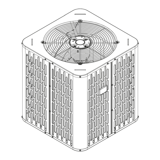
Condensing Units
Models
A5AC4018A
A5AC4024A
A5AC4030A
A5AC4036A
A5AC4042A
A5AC4048A
A5AC4060A
Only qualified personnel should install and service the equipment. The installation, starting up, and servicing of heating, ventilating,
and air-conditioning equipment can be hazardous and requires specific knowledge and training. Improperly installed, adjusted or
altered equipment by an unqualified person could result in death or serious injury. When working on the equipment, observe all pre-
cautions in the literature and on the tags, stickers, and labels that are attached to the equipment.
August 2023
Note: "Graphics in this document are for representation only.
SAFETY WARNING
88-A5AC4001-1A-EN
Actual model may differ in appearance."
Advertisement
Table of Contents

Related Manuals for Trane A5AC4018A


Summary of Contents for Trane A5AC4018A
- Page 1 AHRI rated only with TXV/EEV indoor systems. Some of the benefits of installing approved matched indoor and out- door split systems are maximum efficiency, optimum performance and the best overall system reliability. Condensing Units Models A5AC4018A A5AC4024A A5AC4030A A5AC4036A...
-
Page 2: Section 1. Safety
Section 1. Safety CAUTION CONTAINS REFRIGERANT! NOTE: R454B refrigerant is a blend and should only Failure to follow proper procedures can result in be added to the system in liquid form. personal illness or injury or severe equipment WARNING damage. System contains oil and refrigerant under high HAZARDOUS VOLTAGE! pressure. -
Page 3: Table Of Contents
Table of Contents Section 1. Safety ................................2 Section 2. Unit Location Considerations ........................4 Section 3. Unit Preparation............................5 Section 4. Setting the Unit ............................5 Section 5. Refrigerant Line Considerations ......................5 Section 6. Refrigerant Line Routing ..........................6 Section 7. -
Page 4: Section 2. Unit Location Considerations
2.1 Unit Dimensions and Weight Table 2.1 Unit Dimensions and Weight Models H x D x W (in) Weight* (lb) 36.6 x 29.8 x 29.8 A5AC4018A 32.6 x 29.8 x 29.8 A5AC4024A 36.6 x 29.8 x 29.8 A5AC4030A 32.6 x 29.8 x 29.8 A5AC4036A 36.6 x 34.3 x 34.3... -
Page 5: Section 3. Unit Preparation
Max Line & Lift Lengths RATED Vapor Liquid Vapor Line Liquid Line TOTAL Max LINE SIZES Max Lift (ft.) Line Line Connection Connection Line Length (ft.) A5AC4018A 5/16 5/16 A5AC4024A 5/16 5/16 A5AC4030A 5/16 5/16 A5AC4036A 5/16 5/16 A5AC4042A 5/16... -
Page 6: Section 6. Refrigerant Line Routing
5.3 Required Refrigerant Line Length Determine required line length and lift. You will need this later in STEP 2 of Section 14. Total Line Length = __________ Ft. Line Length Total Vertical Change (lift) = __________ Ft. 5.4 Refrigerant Line Insulation Important: The Vapor Line must always be Vapor Line Liquid Line... - Page 7 8 Feet Maximum Joist/Rafter Isolator Side View 8 Feet Maximum Line Set Secure Vapor line from joists using isolators every 8 ft. Secure Liquid Line directly to Vapor line using tape, wire, or other appro- priate method every 8 ft. Isolation From Joist/Rafter 8 Feet Maximum Wall...
-
Page 8: Section 7. Refrigerant Line Brazing
Section 7. Refrigerant Line Brazing 7.1 Braze The Refrigerant Lines STEP 1 - Remove caps or plugs. Use a deburing tool to debur the pipe ends. Clean both internal and external surfaces of the tubing using an emery cloth. STEP 2 - Remove the pressure tap cap and valve cores from both service valves. STEP 3 - Purge the refrigerant lines and indoor coil with dry nitrogen. -
Page 9: Section 8. Refrigerant Line Leak Check
Section 8. Refrigerant Line Leak Check 8.1 Check For Leaks STEP 1 - Pressurize the refrigerant lines and 600 PSIG evaporator coil to 600 PSIG using dry nitrogen. STEP 2 - Check for leaks by using a soapy solution or bubbles at each brazed location. Note: Remove nitrogen pressure and repair any leaks before continuing. -
Page 10: Section 10. Service Valves
Under no circumstances shall potential sources of ignotion be used in the searching for or detection of refrigerant leaks. The following leak detection methods are deemed acceptable for all refrigerant systems: • Electronic leak detectors calibrated for R454B • Bubble method •... -
Page 11: Section 11. Electrical - Low Voltage
1/4 TURN ONLY COUNTERCLOCKWISE FOR FULL OPEN Unit Side POSITION of Service 3/16” Hex Wrench Valve Rolled Edge to VALVE STEM Captivate Stem Hex Headed UNIT SIDE Valve System OF VALVE PRESSURE TAP PORT Service Port GAS LINE CONNECTION Gas Service Valve Liquid Service Valve Mitigation Board Guidelines •... - Page 12 11.2 Low Voltage Hook-up Diagrams With 5TEM 4, 5, C With 5TAM5, Outdoor Outdoor Thermostat Air Handler Thermostat Air Handler Unit Unit 24 VAC HOT 24 VAC HOT 24 VAC 24 VAC Common Common Blue Blue COOL/HEAT COOL/HEAT 1st STAGE 1st STAGE HEATING HEATING...
-
Page 13: Section 12. Electrical - High Voltage
Section 12. Electrical - High Volta ge 12.1 High Volta ge Power Suppl y WARNING LIVE ELECTRICAL COMPONENTS! During installation, testing, servicing, and troubleshooting of this product, it may be nec- essary to work with live electrical components. Failure to follow all electrical safety precau- tions when exposed to live electrical compo- nents could result in death or serious injury. -
Page 14: Section 14. System Charge Adjustment (Systems Can Be Rated With Txv, Eev Or Piston)
Section 14. System Charge Adjustment (Systems can be rated with TXV, EEV or Piston) NOTE: For systems using a indoor piston metering device, refer to the Superheat charging method and chart. For systems using a TXV or EEV indoor metering device, refer to Subcool charging method and charts. 14.1 Temperature Measurements STEP 1 - Check the outdoor temperatures. - Page 15 STEP 2 - Determine the final subcooling value using R-454B REFRIGERANT CHARGING CHART total Line Length and Lift measured in STEP 1 and ° DESIGN SUBCOOLING ( the charts below. LIQUID TEMP 018 & 030 Models ( ° F) LIQUID GAGE PRESSURE (PSI) SUBCOOL CHARGING CHART CORRECTIONS TABLE (FOR LINE LENGTH AND RISE) 170 172 175 178 181 184 187 1°...
- Page 16 14.3 Charging the Unit STEP 1 - Attain Proper Gage Pressure. Using the Standard R-454B Subcool Charging Chart, adjust refrigerant level to attain proper gage pressure. Note: Use bubble point, per the included chart, for calculating subcooling. Add refrigerant in the Liquid Gage Pressure is lower than the chart value.
- Page 17 Fixed Orifice Superheat Charging Table Indoor Wet Bulb Temp (F) Outdoor Bulb Temp. Using a digital psychrometer, measure the return air wet-bulb temperature at the unit just before the coil. Also measure the outdoor dry-bulb tem- perature. Use these temperatures to locate the target superheat on the charging table. Do not attempt to charge the system if these conditions fall outside of this charging table.
-
Page 18: Section 15. Checkout Procedures
STEP 5 - Complete the ‘Total System Charge’ charge rating label below and label located on the outside of the unit with a permanent marker. Note: Complete the ‘Total System Charge’ chart when fi nal charging is complete. a. Charge added at Factory = ___________ lb/oz b. -
Page 19: Section 16. Refrigerant Circuits (Reference Only)
Section 16. Refrigeration Circuits 018, 030 & 042 Models PRINTED FROM D158514P01 024 & 036 Models PRINTED FROM D157394P01 88-A5AC4001-1A-EN... - Page 20 048 & 060 Models Printed from D159175 88-A5AC4001-1A-EN...
-
Page 21: Section 17. Wiring Diagrams
Section 17. Wiring Diagrams 018 - 048 Models 88-A5AC4001-1A-EN... - Page 22 018 - 048 Models 88-A5AC4001-1A-EN...
- Page 23 060 Models 88-A5AC4001-1A-EN...
- Page 24 060 Models 88-A5AC4001-1A-EN...
-
Page 25: Section 18. Pressure Curves
Section 18. Pressure Curves PRESSURE CURVES (Refer below table for models) INDOOR ENTERING WET BULB CURVES TOP TO BOTTOM 71, 67, 63 AND 59 DEG F. Cooling OD Model @SCFM OUTDOOR TEMPERATURE (Degree F) A5AC4018A1 INDOOR ENTERING WET BULB CURVES TOP TO BOTTOM 71, 67, 63 AND 59 DEG F. - Page 26 PRESSURE CURVES (Refer below table for models) INDOOR ENTERING WET BULB CURVES TOP TO BOTTOM 71, 67, 63 AND 59 DEG F. Cooling OD Model @SCFM OUTDOOR TEMPERATURE (Degree F) A5AC4024A1 A5AC4030A1 INDOOR ENTERING WET BULB CURVES A5AC4036A1 TOP TO BOTTOM 71, 67, 63 AND 59 DEG F.
- Page 27 PRESSURE CURVES (Refer below table for models) INDOOR ENTERING WET BULB CURVES TOP TO BOTTOM 71, 67, 63 AND 59 DEG F. Cooling OD Model @SCFM OUTDOOR TEMPERATURE (Degree F) 1450 A5AC4060A1 INDOOR ENTERING WET BULB CURVES TOP TO BOTTOM 71, 67, 63 AND 59 DEG F.