Table of Contents
Advertisement
Quick Links
Installation, Operation and Maintenance
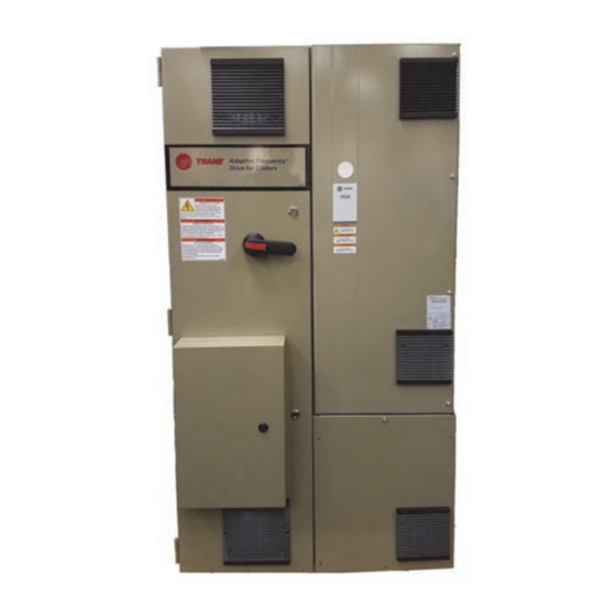
Air-Cooled Adaptive Frequency™
Drive with Tracer® AdaptiView™
Control
Models:
AFDG, AFDU
Only qualified personnel should install and service the equipment. The installation, starting up, and servicing of
heating, ventilating, and air-conditioning equipment can be hazardous and requires specific knowledge and training.
Improperly installed, adjusted or altered equipment by an unqualified person could result in death or serious injury.
When working on the equipment, observe all precautions in the literature and on the tags, stickers, and labels that are
attached to the equipment.
May 2020
Model AFDG
(Remote-Mounted)
SAFETY WARNING
AFDG-SVU01L-EN
Model AFDU
(Unit-Mounted)
Advertisement
Table of Contents

Related Manuals for Trane AFDG


Summary of Contents for Trane AFDG
- Page 1 Installation, Operation and Maintenance Air-Cooled Adaptive Frequency™ Drive with Tracer® AdaptiView™ Control Model AFDU Model AFDG (Unit-Mounted) (Remote-Mounted) Models: AFDG, AFDU SAFETY WARNING Only qualified personnel should install and service the equipment. The installation, starting up, and servicing of heating, ventilating, and air-conditioning equipment can be hazardous and requires specific knowledge and training.
- Page 2 (Global Harmonized System of Classification and compounds have the same potential impact to the Labeling of Chemicals) guidelines for information on environment. Trane advocates the responsible handling of allowable personal exposure levels, proper all refrigerants-including industry replacements for CFCs respiratory protection and handling instructions.
- Page 3 Copyright This document and the information in it are the property of Trane, and may not be used or reproduced in whole or in part without written permission. Trane reserves the right to revise this publication at any time, and to make changes to its content without obligation to notify any person of such revision or change.
-
Page 4: Table Of Contents
....9 Recommended Periodic Maintenance and In- AFDG Model Number Digit Identification spection ....... .38 AFDU Model Number Digit Identification Visual Inspection—Power Removed... -
Page 5: General Information
Equipment terminals and other internal parts of the controller are at line voltage when AC power is Refer to the model number printed on the Trane Adaptive connected to the controller. All ungrounded conductors Frequency Drive nameplate when ordering replacement of the AC power line must be disconnected from the parts or service for the drive. -
Page 6: Controller Checks
7. Check the chassis ground and other connections for performing the startup. tightness. 8. Check all external control connections (this includes 4. Check to see that the AFDG/AFDU is properly ground to the operator station connections) for tightness. earth. See “Grounding the Cabinet,” p. 20 “Input... - Page 7 Follow proper lockout/ tagout procedures to ensure the power cannot be inadvertently energized. For variable frequency drives or other energy storing components provided by Trane or others, refer to the appropriate manufacturer’s literature for allowable waiting periods for discharge of capacitors.
-
Page 8: Overview
• The current never exceeds the rated load amps. • The AFDG/AFDU varies the motor speed in response to the speed command from the UC800 control. The CenTraVac™ Control Panel has full control of the unit operation, including the start/stop functions. If you encounter a fault condition or an alarm on the drive, the Tracer®... -
Page 9: Model Number Descriptions
Model Number Descriptions AFDG Model Number Digit Identification Model number digits are selected and assigned in accordance with the following definitions using the above model number example: Digit 1, 2, 3 — Unit Function 1060 1260 AFD= Adaptive Frequency Drive Digit 4—... -
Page 10: Afdu Model Number Digit Identification
Digit 16 — Connection Type Short Circuit Rating (SCCR) Standard Circuit Breaker High Interrupting Breaker Special Digit 17 — Control Power Option Control Power Transformer 4kVA Power and Ground Wire Length is measured from the back of the panel to the compressor housing. AFDG-SVU01L-EN... -
Page 11: Drive And Cabinet
Drive and Cabinet Enclosure Rating The Trane® cabinet has a NEMA 1 enclosure rating: NEMA 1: Vented. Intended for general-purpose indoor applications. Environmental Conditions Important: Location of the AFDG/AFDU is important if proper performance and normal operating life is to be expected. Therefore, unless... -
Page 12: About The Cabinet
Drive and Cabinet About the Cabinet This section provides cabinet dimension information and shows where the wire entry areas are located. Figure 1. AFDG (remote-mounted) cabinet dimensions: Frame D3 and D4, in. (47.48) 9.10 12.80 AIR FLOW 3.90 1.82 2.50 13.04 MIN... - Page 13 Drive and Cabinet Figure 2. AFDG (remote-mounted) cabinet dimensions: Frame E1 and E2, in. (63.24) 9.10 20.54 AIR FLOW 1.82 3.90 2.80 13.04 MIN CLEARANCE 2.79 120VAC 7.90 CONTROL 15.60 1.88 3.42 MIN / 6.00 MAX PERMISSIBLE WIRE AIR FLOW...
- Page 14 Drive and Cabinet Figure 3. AFDG (remote-mounted) cabinet dimensions: Frame F3, in. Units with Ceramic bearings will not have Common mode Chokes. (126.22) AIR FLOW 9.10 12.80 3.90 18.74 2.50 13.04 MIN 1.85 CLEARANCE 2.80 2.80 2.50 120VAC CONTROL 7.90 15.60...
- Page 15 Drive and Cabinet Figure 4. AFDG (remote-mounted) cabinet dimensions: Frame F4, in. (149.83) AIR FLOW 9.10 20.70 18.74 2.50 13.04 MIN 3.90 CLEARANCE 1.85 2.50 2.80 2.80 120VAC CONTROL 7.90 AIR FLOW 15.60 11.73 1.88 18.86 LOW VOLTAGE 2.91 WIRING 7.90...
- Page 16 • Starter SCR (Short Circuit Rating) = The maximum fault current to which a starter may be exposed and safely AFDG-SVU01L-EN...
-
Page 17: Lifting The Drive
1019 1121 Important: AFDG (remote-mounted) and AFDU (unit- mounted) have differing lift point locations 1145 and lifting procedures. For AFDG, refer to 1187 Figure 6, p. 17 Table 2, p. 17; for AFDU, 1217 refer to Figure 7, p. - Page 18 Use appropriately rated rigging equipment to ensure a vertical lift from each lift eye. • Use of two chain hoists (one for each lift eye), or use of a single hoist with a spreader bar are permissible methods for lifting the drive. AFDG-SVU01L-EN...
-
Page 19: Input Power And Control Wiring
Proper torque for connections depends on both the bolting inadvertently energized. For variable frequency drives materials and the metals being connected. Strand or other energy storing components provided by Trane migration will occur when the copper is under prolonged or others, refer to the appropriate manufacturer’s pressure. -
Page 20: Wire Sizing
Starter panel terminal blocks precaution could result in damage to, or destruction of, the equipment. Use the following steps to ground the AFDG (remote- mounted) cabinet: 1. Open the left-hand enclosure door of the drive. The grounding stud is located just above and to the left of the breaker. - Page 21 Input Power and Control Wiring Figure 8. AFDG (remote-mounted) component layout (see Table 4, p. 20 for drive component list) From 575V Line Local Control Panel (LCP) Motor Leads To Motor Note: Wiring from the drive to the motor is required to be...
- Page 22 Input Power and Control Wiring Figure 9. AFDG (remote-mounted) common mode choke Units with Ceramic bearings will not have common mode chokes Figure 10. AFDG (remote-mounted) open assembly (no doors): F4 Units (F3 Units are similar, but have only two inverters) AFDG-SVU01L-EN...
- Page 23 Input Power and Control Wiring Figure 11. AFDU (unit-mounted) component layout Motor Leads Circuit Breaker Control Power Transformer Panel Cooling AFDG-SVU01L-EN...
- Page 24 Starter Fault cal ntrol Starter nel Module Drive Module Units with ceramic bearings will not get common mode chokes Common Mode Choke* *Units with ceramic bearings will not get common mode chokes AFDG-SVU01L-EN...
-
Page 25: Uc800 Afd Operation
Chiller capacity control, safeties, and limits work in the same manner regardless of whether an AFD is present. The UC800’s AFD speed control algorithm will simultaneously set Inlet Guide Vane (IGV) position and AFDG-SVU01L-EN... -
Page 26: Afd Speed Control
The UC800 uses the greater of the two pressures for the initial speed command. After the compressor runs for a few minutes, the actual condenser pressure is used. The speed will be adjusted every 5 seconds in response to changing pressure ratio and load requirements. AFDG-SVU01L-EN... -
Page 27: Re-Optimization
The control is re-optimized by increasing the AF Surge Boundary Offset Coefficient every minute until surge occurs. When surge occurs, the control will go into surge recovery until the surge flag is removed and all of the re- optimization timers will reset. AFDG-SVU01L-EN... -
Page 28: Surge Recovery
Figure 15. Motor current signature representing surge Present Rectified Sampled Motor Previous Value Current Sampled Value Transitory Pressure Pressure Rebuilding Breakdown Time 1 Surge Occurrence AFDG-SVU01L-EN... -
Page 29: Uc800 Interface To Adaptive Frequency Drive
UC800 to provide a speed reference to the Figure 16. Drive frequency vs. speed reference signal VFD / Starter Module Speed Reference vs. Drive Frequency 60 Hz 38 Hz 10 Vdc 2.0 Vdc AFDG-SVU01L-EN... - Page 30 UC800 AFD Operation Figure 17. AFDG starter module to unit mounted inverter interface block diagram Starter Module to Variable Speed Drive Interface 3 Phase Line Starter UC800 115/240/50/60 Circuit Breaker Starter Module Potential Supply to Transformers, Circuit 115 Vac Line Side of Starter...
- Page 31 Start Relay 2K11 115/240 115/240 24 Vdc Speed Signal 12 mA 5 mA 1/4 Hp 0–10 Vdc VSD Fault At Speed 3 Phase Current Transformers - Load Side of Starter Start Contactor Aux. Oil Pump Interlock Motor Starter UC800 AFDG-SVU01L-EN...
-
Page 32: Service Interface
12-inch, color touch-sensitive for advanced troubleshooting. For more information on screen. Logically organized groups of information—chiller Tracer® TU, visit your local Trane Service company, or modes of operation, active alarms, settings and reports Trane‘s website at www.Trane.com. - Page 33 (a) Use only the factory settings for this application as they are specific to the sales order. Instability and faults may occur by using other settings and is not recommended. Contact your local Trane representative for service when necessary. (b) Compressor motor RLA.
-
Page 34: Afdg/Afdu Startup Procedure
“Sales Order” specific setpoints in the “Starter Configurations for AFD Starters.” These settings are specific to unit/motor combination in the drive. All of the remaining settings are factory-determined default setpoints that are the same on all AFDG/ AFDU air-cooled drives. AFDG-SVU01L-EN... -
Page 35: Drive Settings
8(a) Start select b. With a laptop connected to the chiller and with (a) If the customer is connecting to the remote-mounted AFDG with MOD- Tracer® TU running, enter the binding view menu BUS®, Group 8 parameters MUST be selected. -
Page 36: Default Settings
Hand on key Disabled (0) the drive at the factory for use with Trane® chillers. In the Off key Disabled (0) event that the drive needs to be reset, these parameters will need to be reprogrammed into the drive. -
Page 37: Startup Test Log
Tracer® TU Field Startup View: AFD Maximum Frequency Minimum Frequency AFD Surge Capacity Increase Tracer® TU Status View: Motor Average Line Current Starter Average Phase Voltage Starter Load Power Factor Motor Winding #1 temp Motor Winding #2 temp Motor Winding #3 temp AFDG-SVU01L-EN... -
Page 38: Recommended Periodic Maintenance And Inspection
Frequency drives for centrifugal chillers equipped with 10. Inspect power wire cables and devices to assure no AFDG/AFDU starters. All UC800 chillers will be equipped abrasion is occurring from vibrations against chassis with the LCP as standard on the drive power module. This of cabinets, or other edges. -
Page 39: Troubleshooting
Follow proper lockout/ tagout procedures to ensure the power cannot be inadvertently energized. For variable frequency drives or other energy storing components provided by Trane or others, refer to the appropriate manufacturer’s literature for allowable waiting periods for discharge of capacitors. -
Page 40: Wiring Schematics
Wiring Schematics For reference, an as-built schematic wiring diagram and a field wiring connection diagram are located inside the main control panel door of the chiller. AFDG-SVU01L-EN... - Page 44 For more information, please visit trane.com or tranetechnologies.com. Trane has a policy of continuous product and product data improvement and reserves the right to change design and specifications without notice. We are committed to using environmentally conscious print practices.