Table of Contents
Advertisement
Quick Links
- 1 Section 1. Safety
- 2 Table of Contents
- 3 Section 2. Unit Location Considerations
- 4 Section 5. Refrigerant Line Considerations
- 5 Section 11. Electrical - Low Voltage
- 6 Section 12. Electrical - High Voltage
- 7 Section 14. System Charge Adjustment (Systems Can be Rated with Txv, Eev or Piston)
- 8 Section 15. Checkout Procedures and Troubleshooting
- Download this manual
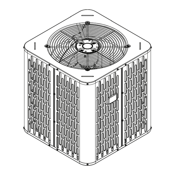
Installer's Guide
Condensing Units
Models
A4AC3018A1000A
A4AC3023A1000A
A4AC3024A1000A
A4AC3029A1000A
A4AC3030A1000A
A4AC3036A1000A
A4AC3042A1000A
A4AC3043A1000A
A4AC3048A1000A
A4AC3060A1000A
Only qualified personnel should install and service the equipment. The installation, starting up, and servicing of heating, ventilating,
and air-conditioning equipment can be hazardous and requires specific knowledge and training. Improperly installed, adjusted or
altered equipment by an unqualified person could result in death or serious injury. When working on the equipment, observe all pre-
cautions in the literature and on the tags, stickers, and labels that are attached to the equipment.
April 2020
Note: "Graphics in this document are for representation only.
SAFETY WARNING
88-A4AC3001-1C-EN
Actual model may differ in appearance."
Advertisement
Table of Contents

Related Manuals for Trane A4AC3018A1000A


Summary of Contents for Trane A4AC3018A1000A
- Page 1 Installer’s Guide Condensing Units Models A4AC3018A1000A A4AC3023A1000A A4AC3024A1000A A4AC3029A1000A A4AC3030A1000A A4AC3036A1000A A4AC3042A1000A A4AC3043A1000A A4AC3048A1000A A4AC3060A1000A Note: “Graphics in this document are for representation only. Actual model may differ in appearance.” SAFETY WARNING Only qualified personnel should install and service the equipment. The installation, starting up, and servicing of heating, ventilating, and air-conditioning equipment can be hazardous and requires specific knowledge and training.
-
Page 2: Section 1. Safety
ALL phases of this installation must comply with or should particular problems arise which are not covered sufficiently for the purchaser’s purposes, the matter should be NATIONAL, STATE AND LOCAL CODES. referred to your installing dealer or local distributor. IMPORTANT — This Document is customer property Note: The manufacturer recommends installing only approved and is to remain with this unit. -
Page 3: Table Of Contents
Table of Contents Section 1. Safety ................................2 Section 2. Unit Location Considerations........................4 Section 3. Unit Preparation ............................6 Section 4. Setting the Unit ............................6 Section 5. Refrigerant Line Considerations ......................7 Section 6. Refrigerant Line Routing .......................... 9 Section 7. -
Page 4: Section 2. Unit Location Considerations
Section 2. Unit Location Considerations 2.1 Unit Dimensions and Weight Table 2.1 Unit Dimensions and Weight Models H x D x W (in) Weight* (lb) A4AC3018A 28.6 x 23.6 x 23.6 A4AC3023A 28.6 x 23.6 x 23.6 A4AC3024A 28.6 x 25.6 x 25.6 A4AC3029A 28.6 x 23.6 x 23.6 A4AC3030A... - Page 5 2.3 Suggested Locations for Best Reliability Ensure the top discharge area is unrestricted for Avoid Install at least five (5) feet above the unit. Near Bedrooms Three (3) feet clearance must be provided in front of the control box (access panels) and any other side requiring service.
-
Page 6: Section 3. Unit Preparation
Section 3. Unit Preparation 3.1 Prepare The Unit For Installation STEP 1 - Check for damage and report prompt- ly to the carrier any damage found to the unit. Section 4. Setting the Unit 4.1 Pad Installation When installing the unit on a support pad, such as a concrete slab, consider the following: •... -
Page 7: Section 5. Refrigerant Line Considerations
Section 5. Refrigerant Line Considerations 5.1 Refrigerant Line and Service Valve Connection Sizes Table 5.1 Line Sizes Service Valve Connection Sizes Max Line & Lift Lengths RATED LINE SIZES Vapor Liquid Vapor Line Liquid Line TOTAL Max Max Lift (ft.) Line Line Connection... - Page 8 5.2 Factory Charge The outdoor condensing units are factory charged with the system charge required for the outdoor condensing unit, ten (10) feet of tested connecting line, and the smallest rated indoor evaporative coil match. Always verify proper system charge via subcooling (TXV/EEV) or superheat (fixed orifice) per the unit nameplate. 5.3 Required Refrigerant Line Length Determine required line length and lift.
-
Page 9: Section 6. Refrigerant Line Routing
5.5 Reuse Existing Refrigerant Lines CAUTION If using existing refrigerant lines make certain that all joints are brazed, not soldered. For retrofit applications, where the existing indoor evaporator coil and/or refrigerant lines will be used, the following precautions should be taken: •... -
Page 10: Section 7. Refrigerant Line Brazing
8 Feet Maximum Wall Isolator Line Set 8 Feet Maximum Side View Secure Vapor Line using isolators every 8 ft. Secure Liquid Line directly to Vapor Line using tape, wire, or other appropriate method every 8 ft. Isolation In Wall Spaces Wall Sealant Ductwork... - Page 11 STEP 2 - Remove the pressure tap cap and valve cores from both service valves. STEP 3 - Purge the refrigerant lines and indoor coil with dry nitrogen. STEP 4 - Wrap a wet rag around the valve body to avoid heat damage and continue the dry nitro- gen purge.
-
Page 12: Section 8. Refrigerant Line Leak Check
STEP 5 - Replace the pressure tap valve cores after the service valves have cooled. Section 8. Refrigerant Line Leak Check 8.1 Check For Leaks STEP 1 - Pressurize the refrigerant lines and 150 PSIG evaporator coil to 150 PSIG using dry nitrogen. STEP 2 - Check for leaks by using a soapy solu- tion or bubbles at each brazed location. -
Page 13: Section 9. Evacuation
Section 9. Evacuation 9.1 Evacuate the Refrigerant Lines and Indoor Coil Important: Do not open the service valves until the refrigerant lines and indoor coil leak check and evacuation are complete. 0350 Microns STEP 1 - Evacuate until the micron gauge reads no higher than 350 microns, then close off the valve to the vacuum pump. -
Page 14: Section 11. Electrical - Low Voltage
10.1 Open the Liquid Service Valve WARNING Extreme caution should be exercised when opening the Liquid Line Service Valve. Turn counterclockwise until the valve stem just touches the rolled edge. No torque is required. Unit Side 3/16” Hex Wrench Failure to follow this warning will result in abrupt of Service release of system charge and may result in Valve... - Page 15 11.2 Low Voltage Hook-up Diagrams AC SYSTEMS HEAT PUMP SYSTEMS Outdoor Outdoor Thermostat Air Handler Thermostat Air Handler Unit Unit 24 VAC HOT 24 VAC HOT 24 VAC 24 VAC Common Common Blue Blue COOL/HEAT COOLING 1st STAGE HEATING HEAT 2nd STAGE White White...
-
Page 16: Section 12. Electrical - High Voltage
Section 12. Electrical - High Voltage 12.1 High Voltage Power Supply WARNING LIVE ELECTRICAL COMPONENTS! During installation, testing, servicing, and troubleshooting of this product, it may be nec- essary to work with live electrical components. Failure to follow all electrical safety precau- tions when exposed to live electrical compo- nents could result in death or serious injury. -
Page 17: Section 13. Start Up
Section 13. Start Up 13.1 System Start Up STEP 1 - Ensure Sections 7 through 12 have been completed. STEP 2 - Set System Thermostat to OFF. DONE CANCEL STEP 3 - Turn on disconnect(s) to apply power to the indoor and outdoor units. STEP 4 - Wait one (1) hour before starting the unit if compressor crankcase heater acces- sory is used and the Outdoor Ambient is below... -
Page 18: Section 14. System Charge Adjustment (Systems Can Be Rated With Txv, Eev Or Piston)
Section 14. System Charge Adjustment (Systems can be rated with TXV, EEV or Piston) NOTE: For systems using a indoor piston metering device, refer to the Superheat charging method and chart. For systems using a TXV or EEV indoor metering device, refer to Subcool charging method and charts. 14.1 Temperature Measurements STEP 1 - Check the outdoor temperatures. - Page 19 STEP 2 - Determine the final subcooling value using total Line Length and Lift measured in STEP 1 and the charts below. 1.5 Ton Units 2 Ton Units SUBCOOL CHARGING CHART CORRECTIONS TABLE (FOR LINE LENGTH AND RISE) SUBCOOL CHARGING CHART CORRECTIONS TABLE (FOR LINE LENGTH AND RISE) 1°...
- Page 20 STEP 3 - Stabilize the system by operating for a minimum of 20 minutes. At startup, or whenever charge is removed or 20 MIN. added, the system must be operated for a mini- mum of 20 minutes to stabilize before accurate measurements can be made.
- Page 21 STEP 6 - Adjust refrigerant level to attain proper gage pressure. Add refrigerant if the Liquid Gage Pressure is lower than the chart value. 1. Connect gages to refrigerant bottle and unit as illustrated. 2. Purge all hoses. 3. Open bottle. 4.
- Page 22 Fixed Orifice Superheat Charging Table Indoor Wet Bulb Temp (F) Outdoor Bulb Temp. Using a digital psychrometer, measure the return air wet-bulb temperature at the unit just before the coil. Also measure the outdoor dry-bulb tem- perature. Use these temperatures to locate the target superheat on the charging table. Do not attempt to charge the system if these conditions fall outside of this charging table.
- Page 23 STEP 9 - Record System Information for refer- ence. Record system pressures and temperatures after charging is complete. Measured Suction Line Temp = __________ º F Outdoor model number = _________________ Liquid Gage Pressure = __________ PSIG Measured Outdoor Ambient = __________ º F Suction Gage Pressure = __________ PSIG Measured Indoor Ambient = __________ º...
-
Page 24: Section 15. Checkout Procedures And Troubleshooting
STEP 2 - Stabilize the system by operating for a minimum of 20 minutes. 20 MIN. At startup, or whenever charge is removed or added, the system must be operated for a mini- mum of 20 minutes to stabilize before accurate measurements can be made. - Page 25 15.2 Troubleshooting TROUBLESHOOTING Compressor fails to start Contactor check Is contactor Go To: Compressor won’t run energized? (contacts closed) Check for 24 volts AC across contactor coil Is voltage present at Replace contactor contactor coil? Check control transformer and control fuse Jumper R to Y low Is the control Does the...
- Page 26 TROUBLESHOOTING Compressor won’t run Contactor is closed Check for high voltage to contactor Check for open IOL Is high voltage present (Internal Overload) at T1 and T2 ? Check resistance of C to S and C to R Does the Check power resistance check Allow compressor...
- Page 27 15.2 Troubleshooting SYSTEM FAULTS REFRIGERANT CIRCUIT Head Pressure Too High Head Pressure Too Low Suction Pressure Too High Suction Pressure Too Low Liquid Refrig. Floodback (TXV/EEV) Liquid Refrig. Floodback (Cap. Tube) I.D. Coil Frosting Compressor Runs Inadequate or No Cooling/Htg ELECTRICAL Compressor &...
-
Page 28: Section 16. Refrigerant Circuits
Section 16. Refrigerant Circuits 1.5 & 2 Ton Units PRINTED FROM D157394P02 REV A 2.5 & 3.5 Ton Units PRINTED FROM D157394P01 88-A4AC3001-1C-EN... - Page 29 3 & 4 Ton Units PRINTED FROM D158796P01 REV A 5 Ton Units PRINTED FROM C151867 88-A4AC3001-1C-EN...
- Page 30 Notes 88-A4AC3001-1C-EN...
- Page 31 Notes 88-A4AC3001-1C-EN...
- Page 32 About Trane and American Standard Heating and Air Conditioning Trane and American Standard create comfortable, energy efficient indoor environments for residential applications. For more information, please visit www.trane.com or www.americanstandardair.com The AHRI Certified mark indicates company participation in the AHRI Certification program. For verification of individual certified products, go to ahridirectory.org.