
Related Manuals for Hobart H100S2-10


Summary of Contents for Hobart H100S2-10
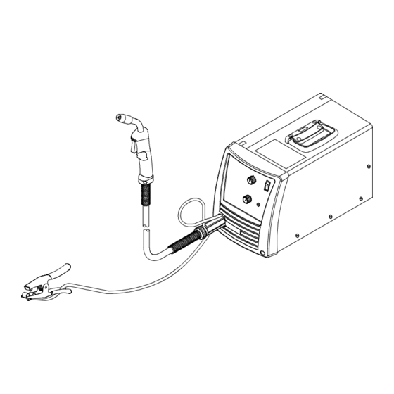
- Page 1 OM-258 267D 2014−08 Processes MIG (GMAW) Welding Flux Cored (FCAW) Welding Description Arc Welding Power Source And Wire Feeder Handler 140 And H100S2-10 Gun File: MIG (GMAW) www.HobartWelders.com...
-
Page 2: Table Of Contents
............Hobart is registered to 7-2. -
Page 3: Section 1 − Safety Precautions - Read Before Using
SECTION 1 − SAFETY PRECAUTIONS - READ BEFORE USING som 2013−09 Protect yourself and others from injury — read, follow, and save these important safety precautions and operating instructions. 1-1. Symbol Usage DANGER! − Indicates a hazardous situation which, if Indicates special instructions. - Page 4 D Remove stick electrode from holder or cut off welding wire at FUMES AND GASES can be hazardous. contact tip when not in use. D Wear body protection made from durable, flame−resistant material Welding produces fumes and gases. Breathing (leather, heavy cotton, wool). Body protection includes oil-free these fumes and gases can be hazardous to your clothing such as leather gloves, heavy shirt, cuffless trousers, high health.
-
Page 5: Additional Symbols For Installation, Operation, And Maintenance
1-3. Additional Symbols For Installation, Operation, And Maintenance FIRE OR EXPLOSION hazard. MOVING PARTS can injure. D Do not install or place unit on, over, or near D Keep away from moving parts such as fans. combustible surfaces. D Keep all doors, panels, covers, and guards D Do not install unit near flammables. -
Page 6: California Proposition 65 Warnings
1-4. California Proposition 65 Warnings Welding or cutting equipment produces fumes or gases This product contains chemicals, including lead, known to which contain chemicals known to the State of California to the state of California to cause cancer, birth defects, or other cause birth defects and, in some cases, cancer. -
Page 7: Section 2 − Consignes De Sécurité − Lire Avant Utilisation
SECTION 2 − CONSIGNES DE SÉCURITÉ − LIRE AVANT UTILISATION fre_som_2013−09 Pour écarter les risques de blessure pour vous−même et pour autrui — lire, appliquer et ranger en lieu sûr ces consignes relatives aux précautions de sécurité et au mode opératoire. 2-1. - Page 8 D Ne pas raccorder plus d’une électrode ou plus d’un câble de D Avoir recours à des écrans protecteurs ou à des rideaux pour masse à une même borne de sortie de soudage. Débrancher le protéger les autres contre les rayonnements les éblouissements câble pour le procédé...
-
Page 9: Dangers Supplémentaires En Relation Avec L'installation, Le Fonctionnement Et La Maintenance
LES BOUTEILLES peuvent exploser DES PIECES DE METAL ou DES si elles sont endommagées. SALETES peuvent provoquer des blessures dans les yeux. Les bouteilles de gaz comprimé contiennent du gaz sous haute pression. Si une bouteille est D Le soudage, l’écaillement, le passage de la endommagée, elle peut exploser. - Page 10 LES CHARGES ÉLECTROSTATI- RAYONNEMENT HAUTE QUES peuvent endommager les cir- FRÉQUENCE (H.F.) risque cuits imprimés. provoquer des interférences. D Établir la connexion avec la barrette de terre D Le rayonnement haute fréquence (H.F.) peut avant de manipuler des cartes ou des pièces. provoquer des interférences avec les équi- pements de radio−navigation et de com- D Utiliser des pochettes et des boîtes antista-...
-
Page 11: Proposition Californienne 65 Avertissements
2-4. Proposition californienne 65 Avertissements Les équipements de soudage et de coupage produisent des Ce produit contient des produits chimiques, notamment du fumées et des gaz qui contiennent des produits chimiques plomb, dont l’État de Californie reconnaît qu’ils provoquent dont l’État de Californie reconnaît qu’ils provoquent des mal- des cancers, des malformations congénitales ou d’autres formations congénitales et, dans certains cas, des cancers. - Page 12 OM-258 267 Page 10...
-
Page 13: Section 3 − Definitions
A complete Parts List is available at www.HobartWelders.com SECTION 3 − DEFINITIONS 3-1. Miscellaneous Symbols And Definitions Amperage Voltage Hertz Negative Direct Current Positive Single Phase Input (DC) Output Voltage Input Do Not Switch Gas Metal Arc Wire Feed Line Connection While Welding Welding (GMAW) Suitable For... -
Page 14: Duty Cycle And Overheating
A complete Parts List is available at www.HobartWelders.com 4-3. Duty Cycle And Overheating Duty Cycle is percentage of 10 minutes that unit can weld at rated load without overheating. If unit overheats, thermostat(s) opens, over temperature LED lights, output stops, and cooling fan runs. -
Page 15: Section 5 − Installation
A complete Parts List is available at www.HobartWelders.com SECTION 5 − INSTALLATION 5-1. Selecting A Location Plug From Unit Grounded Receptacle Locate unit near correct input power supply. Special installation may be required where gasoline or volatile liquids are present − see NEC Article 511 or CEC 18 in. -
Page 16: Installing Work Clamp
A complete Parts List is available at www.HobartWelders.com 5-3. Installing Work Clamp Work Clamp Connection hardware must be tightened with proper tools. Do not just Work Cable From Unit hand tighten hardware. A loose electrical connection will cause poor weld performance and excessive heating of the work clamp. -
Page 17: Installing Gas Supply
A complete Parts List is available at www.HobartWelders.com 5-6. Installing Gas Supply Obtain gas cylinder and chain to running gear, wall, other stationary support so cylinder cannot fall and break off valve. DO NOT use Argon/Mixed gas regulator/flowmeter with CO shielding gas. -
Page 18: Connecting Input Power
A complete Parts List is available at www.HobartWelders.com 5-7. Connecting Input Power Do not move or operate unit where it could tip. A 115 volts AC, 20 ampere individual circuit Plug From Unit Installation must meet all National protected by time-delay fuses or circuit Receptacle −... -
Page 19: Installing Wire Spool And Adjusting Hub Tension
A complete Parts List is available at www.HobartWelders.com 5-9. Installing Wire Spool And Adjusting Hub Tension Installing 4 in. (102 mm) Wire Spool When a slight force is needed to turn spool, tension is set. Installing 8 in. (203 mm) Wire Spool Adapter used with 8 in. -
Page 20: Threading Welding Wire
A complete Parts List is available at www.HobartWelders.com 5-11. Threading Welding Wire Wire Spool Welding Wire Inlet Wire Guide Pressure Adjustment Knob Drive Roll Gun Conduit Cable Lay gun cable out straight. Tools Needed: Hold wire tightly to keep it from unraveling. 6 in. - Page 21 A complete Parts List is available at www.HobartWelders.com Use pressure indicator scale to set a desired drive roll pressure. (Start with a setting of 2 on the scale.) Tighten Pressure Indicator Scale Be sure that wire is positioned in proper feed roll groove. Remove gun nozzle and contact tip.
-
Page 22: Section 6 − Operation
A complete Parts List is available at www.HobartWelders.com SECTION 6 − OPERATION 6-1. Controls 258 346-A Wire Speed Control thicker the material that can be welded Gun Trigger Switch (see weld setting label in welding power Use control to select a wire feed speed. As Pressing gun trigger energizes wire feed source or Section 6-2). -
Page 23: Weld Parameter Chart
A complete Parts List is available at www.HobartWelders.com 6-2. Weld Parameter Chart 258 069-B OM-258 267 Page 21... -
Page 24: Section 7 − Maintenance & Troubleshooting
A complete Parts List is available at www.HobartWelders.com SECTION 7 − MAINTENANCE & TROUBLESHOOTING 7-1. Routine Maintenance Disconnect power before maintaining. Maintain more often during severe condi- tions. Reference n = Check Z = Change ~ = Clean l = Replace * To be done by Factory Authorized Service Agent 3 Months l Damaged Or Unreadable Labels... -
Page 25: Changing Drive Roll Or Wire Inlet Guide
A complete Parts List is available at www.HobartWelders.com 7-4. Changing Drive Roll Or Wire Inlet Guide Inlet Wire Guide Securing Screw Inlet Wire Guide Loosen thumbscrew. Slide tip as close to drive rolls as possible without touching. Tighten thumbscrew. Be sure gun is fully inserted into drive Drive Roll housing. -
Page 26: Cleaning Or Replacing Gun Liner
A complete Parts List is available at www.HobartWelders.com 7-6. Cleaning Or Replacing Gun Liner Disconnect gun from unit. Head Tube 10 mm Remove liner. 8 mm Remove nozzle, contact tip and tip adapter/gas diffuser. Blow out gun casing. Lay gun cable out straight before installing new liner. -
Page 27: Replacing Switch And/Or Head Tube
A complete Parts List is available at www.HobartWelders.com 7-7. Replacing Switch And/Or Head Tube Turn Off welding power source/wire feeder and disconnect gun. Remove handle half. Remove screws from handle. Remove switch housing. Install new switch and connect leads (polarity is not important). Reassemble in reverse order. -
Page 28: Troubleshooting Table
A complete Parts List is available at www.HobartWelders.com 7-8. Troubleshooting Table Trouble Remedy Secure power cord plug in receptacle (see Section 5-7). No weld output; wire does not feed; fan does not run. Replace building line fuse or reset circuit breaker if open. Place Power switch in On position (see Section 6-1). -
Page 29: Section 8 − Electrical Diagram
SECTION 8 − ELECTRICAL DIAGRAM 257 502-A Figure 8-1. Circuit Diagram OM-258 267 Page 27... -
Page 30: Section 9 − Gmaw Welding (Mig) Guidelines
SECTION 9 − GMAW WELDING (MIG) GUIDELINES 9-1. Typical GMAW (MIG) Process Connections Regulator/ Flowmeter Weld current can damage electronic parts in vehicles. Disconnect both battery Wire Feeder/ cables before welding on a Power Source vehicle. Place work clamp as close to the weld as possible. - Page 31 9-3. Holding And Positioning Welding Gun Welding wire is energized when gun trigger is pressed. Before lowering helmet and pressing trigger, be sure wire is no more than 1/2 in. (13 mm) past end of nozzle, and tip of wire is positioned correctly on seam. Hold Gun and Control Gun Trigger Workpiece...
- Page 32 9-5. Gun Movement During Welding Normally, a single stringer bead is satisfactory for most narrow groove weld joints; however, for wide groove weld joints or bridging across gaps, a weave bead or multiple stringer beads works better. Stringer Bead − Steady Movement Along Seam Weave Bead −...
- Page 33 9-8. Troubleshooting − Excessive Spatter Excessive Spatter − scattering of molten metal particles that cool to solid form near weld bead. S-0636 Possible Causes Corrective Actions Wire feed speed too high. Select lower wire feed speed. Voltage too high. Select lower voltage range. Electrode extension (stickout) too long.
- Page 34 9-11. Troubleshooting − Lack Of Penetration Lack Of Penetration − shallow fusion between weld metal and base metal. Lack of Penetration Good Penetration S-0638 Possible Causes Corrective Actions Improper joint preparation. Material too thick. Joint preparation and design must provide access to bottom of groove while maintaining proper welding wire extension and arc characteristics.
- Page 35 9-14. Troubleshooting − Waviness Of Bead Waviness Of Bead − weld metal that is not parallel and does not cover joint formed by base metal. S-0641 Possible Causes Corrective Actions Welding wire extends too far out of nozzle. Be sure welding wire extends not more than 1/2 in. (13 mm) beyond nozzle. Unsteady hand.
- Page 36 9-16. Common GMAW (MIG) Shielding Gases This is a general chart for common gases and where they are used. Many different combinations (mixtures) of shielding gases have been developed over the years. The most commonly used shielding gases are listed in the following table.
- Page 37 Problem Probable Cause Remedy Wire feeds, but no gas flows. Gas cylinder empty. Replace empty gas cylinder. Gas nozzle plugged. Clean or replace gas nozzle. Gas cylinder valve not open or flowmeter not adjusted. Open gas valve at cylinder and adjust flow rate. Restriction in gas line.
-
Page 38: Section 10 − Accessories/Consumables
For CO shielding gas. Use with replacement gas 237 702** Regulator/Flowmeter hose 144 108. *Available at farm and tool supply retailers. ** Available at Hobart/Miller welding distributors. 10-2. Consumables Item Hobart Package Part No.* Miller Package Part No. ** Contact Tips .023/.025 in. - Page 39 Effective January 1, 2014 5/3/1 WARRANTY applies to all Hobart welding equipment, plasma cutters and spot welders with a Warranty Questions? serial number preface of ME or newer. Call This limited warranty supersedes all previous Hobart warranties and is exclusive with 1-800-332-3281 no other guarantees or warranties expressed or implied.
- Page 40 Thank you for purchasing Hobart. Our trained technical support team is dedicated to your satisfaction. For questions regarding performance, op- eration, or service, contact us! Resources Available Always provide Model Name and Serial/Style Number. To locate a Service Center: Call 1-800-332-3281 or visit our website at www.HobartWelders.com/wheretobuy...