Table of Contents
Advertisement
Quick Links
Advertisement
Table of Contents

Related Manuals for Supero SC113M Series


Summary of Contents for Supero SC113M Series
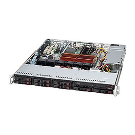
- Page 1 UPER ® SC113M Chassis Series SC113MTQ-560CB SC113MTQ-360CB USER’S MANUAL 1.0a...
- Page 2 SC113M Chassis Manual The information in this User’s Manual has been carefully reviewed and is believed to be accurate. The vendor assumes no responsibility for any inaccuracies that may be contained in this document, makes no commitment to update or to keep current the information in this manual, or to notify any person or organization of the updates.
- Page 3 Preface Preface This manual is written for professional system integrators and PC technicians. It provides information for the installation and use of the SC113M chassis. Installation and maintenance should be performed by experienced technicians only. Supermicro’s SC113M 1U chassis packages outstanding high-end performance into an astonishingly short 20”...
- Page 4 SC113M Chassis Manual Manual Organization Chapter 1: Introduction The introduction provides a checklist of the main components included with this chassis and describes the main features of the SC113M chassis. This chapter also includes contact information. Chapter 2: System Safety This chapter lists warnings, precautions, and system safety.
- Page 5 Preface Appendix A: Chassis Cables This section references cables, which are compatible with your SC113M system. Re- fer to our Web site for additional information on cabling at www.supermicro.com. Appendix B: Power Supply This chapter lists supported power supply information for your SC113M system. Refer to our Web site for additional details at www.supermicro.com.
-
Page 6: Table Of Contents
SC113M Chassis Manual Table of Contents Chapter 1 Introduction Overview ......................1-1 Shipping List ....................1-1 Contacting Supermicro ..................1-2 Returning Merchandise for Service..............1-3 Chapter 2 System Safety Overview ......................2-1 Warnings and Precautions ................2-1 Preparing for Setup ..................2-1 Electrical Safety Precautions ................ - Page 7 Preface Checking the Air Flow ..................5-9 Installation Complete ..................5-9 System Fans ....................5-10 5-10 Power Supply ....................5-12 5-11 Removing the Backplane ................5-13 5-12 Installing the Backplane ................5-14 Chapter 6 Rack Installation Overview ......................6-1 Unpacking the System ..................6-1 Preparing for Setup ..................
- Page 8 SC113M Chassis Manual Notes viii...
-
Page 9: Chapter 1 Introduction
Chapter 1: Introduction Chapter 1 Introduction Overview Supermicro’s SC113M 1U chassis featues eight hot-swappable 2.5” SAS/SATA hard drive bays. Only SAS or enterprise HDDs are recommended. The SC113M chassis includes a 360W or a 560W high-efficiency power supply. One slim DVD- ROM drive is included on the SC113MTQ-560CB model, and is optional on the SC113MTQ-360CB model. -
Page 10: Contacting Supermicro
SC113M Chassis Manual Contacting Supermicro Headquarters Address: Super Micro Computer, Inc. 980 Rock Ave. San Jose, CA 95131 U.S.A. Tel: +1 (408) 503-8000 Fax: +1 (408) 503-8008 Email: marketing@supermicro.com (General Information) support@supermicro.com (Technical Support) Web Site: www.supermicro.com Europe Address: Super Micro Computer B.V. Het Sterrenbeeld 28, 5215 ML 's-Hertogenbosch, The Netherlands Tel:... -
Page 11: Returning Merchandise For Service
Chapter 1: Introduction Returning Merchandise for Service A receipt or copy of your invoice marked with the date of purchase is required be- fore any warranty service will be rendered. You can obtain service by calling your vendor for a Returned Merchandise Authorization (RMA) number. When returning to the manufacturer, the RMA number should be prominently displayed on the outside of the shipping carton, and mailed prepaid or hand-carried. - Page 12 SC113M Chassis Manual Notes...
-
Page 13: Chapter 2 System Safety
Chapter 2: System Safety Chapter 2 System Safety Overview This chapter provides a quick setup checklist to get your chassis up and running. Following the steps in the order provided should enable you to have your chassis up and operational within a minimal amount of time. This quick setup assumes that you are an experienced technician, familiar with common concepts and terminology. -
Page 14: Electrical Safety Precautions
SC113M Chassis Manual Electrical Safety Precautions Basic electrical safety precautions should be followed to protect yourself from harm and the SC113M from damage: • Be aware of the locations of the power on/off switch on the chassis as well as the room’s emergency power-off switch, disconnection switch or electrical outlet. -
Page 15: General Safety Precautions
Chapter 2: System Safety • Please handle used batteries carefully. Do not damage the battery in any way; a damaged battery may release hazardous materials into the environment. Do not discard a used battery in the garbage or a public landfill. Please comply with the regulations set up by your local hazardous waste management agency to dispose of your used battery properly. - Page 16 SC113M Chassis Manual • Use a grounded wrist strap designed to prevent static discharge. • Keep all components and printed circuit boards (PCBs) in their antistatic bags until ready for use. • Touch a grounded metal object before removing any board from its antistatic bag.
-
Page 17: Chapter 3 Chassis Components
Chapter 3 Chassis Components Chapter 3 Chassis Components Overview This chapter describes the most common components included with your chassis. Some components listed may not be included or compatible with your particular chassis model. For more information, see the installation instructions detailed later in this manual. -
Page 18: Power Supply
SC113M Chassis Manual Power Supply Each SC113M chassis model includes a high-efficiency power supply rated at 360 or 560 Watts. In the unlikely event your power supply fails, replacement is simple and can be done without tools. Air Shroud Air shrouds are shields, usually plastic, that channel air directly to where it is needed. Always use the air shroud included with your chassis. -
Page 19: Chapter 4 System Interface
Chapter 4: System Interface Chapter 4 System Interface Overview There are several LEDs on the control panel as well as others on the drive carriers to keep you constantly informed of the overall status of the system as well as the activity and health of specific components. -
Page 20: Control Panel Buttons
SC113M Chassis Manual Control Panel Buttons There are three push-buttons located on the front of the chassis. These are (in order from left to right) a reset button and a power on/off button. • UID: Depressing the UID (unit identifier) button illuminates an LED on both the front and rear of the chassis for easy system location in large stack confi gura- tions. - Page 21 Chapter 4: System Interface • When this LED flashes it indicates a fan failure. When Overheat/Fan Fail: continuously on (not flashing) it indicates an overheat condition, which may be caused by cables obstructing the airflow in the system or the ambient room temperature being too warm.
-
Page 22: Drive Carrier Leds
SC113M Chassis Manual Drive Carrier LEDs Your chassis uses SAS or SATA, but not both at the same time. SAS/SATA Drives Each SAS/SATA drive carrier has two LEDs. • Green: Each Serial ATA drive carrier has a green LED. When illuminated, this green LED (on the front of the SATA drive carrier) indicates drive activity. -
Page 23: Chapter 5 Chassis Setup And Maintenance
Chapter 5: Chassis Setup and Maintenance Chapter 5 Chassis Setup and Maintenance Overview This chapter covers the steps required to install components and perform mainte- nance on the SC113M chassis. The only tool you will need to install components and perform maintenance is a Phillips screwdriver, and under certain circumstances, a hex wrench. -
Page 24: Removing The Chassis Cover
SC113M Chassis Manual Removing the Chassis Cover Figure 5-1: Removing the Chassis Cover Removing the Chassis Cover the Chassis Cover: Slide the cover toward the rear of the chassis. Lift the cover upwards and off of the chassis. Warning: Except for short periods of time, do NOT operate the server without the cover in place. -
Page 25: Installing Hard Drives
Chapter 5: Chassis Setup and Maintenance Installing Hard Drives Figure 5-2: Removing Hard Drive Tray The SC113M accepts eight hot-swappable 2.5" hard drives. Only SAS or enterprise HDDs are recommended. Removing Hard Drive Trays from the Chassis Press the release button on the drive carrier. This extends the drive bay handle. - Page 26 SC113M Chassis Manual Figure 5-3: Chassis Drive Tray Installing a Hard Drive into a Drive Carrier Insert a drive into the carrier with the PCB side facing down and the connec- tor end toward the rear of the carrier. Align the drive in the carrier so that the screw holes of both line up. Note that there are holes in the carrier marked “SATA”...
-
Page 27: Installing The Dvd-Rom Drive
Chapter 5: Chassis Setup and Maintenance Installing the DVD-ROM Drive Figure 5-4: Installing the DVD-ROM Drive The SC113M chassis includes one slim DVD-ROM drive. Installing the DVD-ROM Drive Attach the backplate (A) to the rear of the DVD-ROM drive using the two screws provided. -
Page 28: Installing The Motherboard
SC113M Chassis Manual Installing the Motherboard Installing the Motherboard Review the documentation that came with your motherboard. Become familiar with component placement, requirements, precautions, and cable connec- tions. Open the chassis cover. As required by your motherboard, install standoffs in any areas that do not have a permanent standoff. -
Page 29: Permanent And Optional Standoffs
Chapter 5: Chassis Setup and Maintenance Chassis Standoffs Figure 5-6: Chassis Standoffs Permanent and Optional Standoffs Standoffs prevent short circuits by securing space between the motherboard and the chassis surface. The SC113M chassis includes permanent standoffs in locations used by most motherboards. These standoffs accept the rounded Phillips head screws included in the SC113M accessories packaging. -
Page 30: Installing The Air Shroud
SC113M Chassis Manual Installing the Air Shroud Figure 5-7: Air Shroud Installation Air shrouds concentrate airflow to maximize fan efficiency. The SC113M chassis air shroud does not require screws to set up. Installing the Air Shroud Lay the chassis on a flat, stable surface and remove the chassis cover. If necessary, move any cables that interfere with the air shroud placement. -
Page 31: Checking The Air Flow
Chapter 5: Chassis Setup and Maintenance Checking the Air Flow Checking the Server's Air Flow Make sure there are no objects to obstruct airflow in and out of the server. In addition, if you are using a front bezel, make sure the bezel's filter is replaced periodically. -
Page 32: System Fans
SC113M Chassis Manual System Fans The SC113M chassis includes four heavy-duty fans with open slots for two additional fans to provide cooling for the chassis. These fans circulate air through the chassis as a means of lowering the chassis internal temperature. Replacing a System Fan If necessary, open the chassis while the power is running to determine which fan requires changing. - Page 33 Chapter 5: Chassis Setup and Maintenance Figure 5-8: Installing the Fan Tray into the Chassis Figure 5-9: Fan Tray Secured to the Chassis 5-11...
-
Page 34: 5-10 Power Supply
SC113M Chassis Manual 5-10 Power Supply The SC113M chassis has a 360 or 560 Watt power supply. This power supply is auto-switching capable. This enables it to automatically sense and operate at a 100v to 240v input voltage. An amber light will be illuminated on the power supply when the power is off. -
Page 35: 5-11 Removing The Backplane
Chapter 5: Chassis Setup and Maintenance 5-11 Removing the Backplane The SC113M chassis backplane is located behind the hard drives and in front of the front system fans. In order to change jumper settings on the backplane, it may be necessary to remove the backplane from the chassis. Removing the Backplane from the Chassis Power down and unplug the system from any power source. -
Page 36: 5-12 Installing The Backplane
SC113M Chassis Manual 5-12 Installing the Backplane Installing the Backplane into the Chassis Lower the backplane into the chassis sliding it into the clips on the floor of the chassis and aligning the mounting holes in the backplane, with the mounting holes in the chassis. -
Page 37: Chapter 6 Rack Installation
Chapter 6: Rack Installation Chapter 6 Rack Installation Overview This chapter provides a quick setup checklist to get your chassis up and running. Following these steps in the order given should enable you to have the system operational within a minimum amount of time. Unpacking the System You should inspect the box the chassis was shipped in and note if it was damaged in any way. -
Page 38: Rack Precautions
SC113M Chassis Manual Warnings and Precautions! Rack Precautions • Ensure that the leveling jacks on the bottom of the rack are fully extended to the floor with the full weight of the rack resting on them. • In single rack installation, stabilizers should be attached to the rack. •... -
Page 39: Rack Mounting Considerations
Chapter 6: Rack Installation Rack Mounting Considerations Ambient Operating Temperature If installed in a closed or multi-unit rack assembly, the ambient operating tempera- ture of the rack environment may be greater than the ambient temperature of the room. Therefore, consideration should be given to installing the equipment in an environment compatible with the manufacturer’s maximum rated ambient tempera- ture (Tmra). -
Page 40: Identifying The Sections Of The Rack Rails
SC113M Chassis Manual Rack Mounting Instructions This section provides information on installing the SC113M chassis into a rack unit with the rails provided. There are a variety of rack units on the market, which may mean the assembly procedure will differ slightly. You should also refer to the instal- lation instructions that came with the rack unit you are using. - Page 41 Chapter 6: Rack Installation Figure 6-2: Identifying the Sections of the Rack Rails (right side rail shown) The Inner Rail Extension The inner rails are pre-attached and do not interfere with normal use of the chassis if you decide not to use a server rack. Attach the inner rail extension to stabilize the chassis within the rack.
-
Page 42: Outer Rack Rails
SC113M Chassis Manual Secure to the Front of the Rack Secure to the Rear of the Rack Attach Outer Racks together Figure 6-3: Assembling the Outer Rails Outer Rack Rails Outer rails attach to the server rack and hold the server in place. The outer rails for the SC113M chassis extend between 30 inches and 33 inches. - Page 43 Chapter 6: Rack Installation Figure 6-4: Installing into a Rack Installing the Chassis into a Rack Confirm that chassis includes the inner rails and rail extensions. Also, confirm that the outer rails are installed on the rack. Line chassis rails with the front of the rack rails. Slide the chassis rails into the rack rails, keeping the pressure even on both sides (It may be necessary to depress the locking tabs when inserting).
- Page 44 SC113M Chassis Manual Figure 6-5: Installing into an Open Rack Installing the Chassis into a Mid-Mount Position (Telco) Rack Use the two L-shaped brackets on either side of the chassis (four total). Determine how far the chassis will extend out the front of the rack. Larger chassis should be positioned to balance the weight between front and back.
-
Page 45: Appendix A Sc113M Chassis Cables
Appendix A Chassis Cables Appendix A SC113M Chassis Cables Overview This appendix lists supported cables for your chassis system. It only includes the most commonly used components and configurations. For more compatible cables, refer to the manufacturer of the motherboard you are using and our Web site at: www.supermicro.com. - Page 46 SC113M Chassis Manual Compatible Cables These cables are compatible with the SC113M Chassis. This section lists cables included with the SC113M Chassis packages. Alternate SAS/SATA Cables Some compatible motherboards have different connectors. If your motherboard has only one SAS connector that the SAS/SATA cables must share, use one of the following cables.
- Page 47 Appendix A Chassis Cables Extending Power Cables Although Super Micro chassis are designed with to be efficient and cost-effective, some compatible motherboards have power connectors located in different areas. To use these motherboards you may have to extend the power cables to the mother boards.
- Page 48 SC113M Chassis Manual Notes...
-
Page 49: Appendix Bsc113M Power Supply Specifications
Appendix B Power Supply Specifications Appendix B SC113M Power Supply Specifications This appendix lists power supply specifications for your chassis system. SC113MTQ-560CB 560W MFR Part # PWS-562-1H 100-240V Rated AC 60-50Hz Voltage 6.5 - 2.6 Amp +5V standby 2 Amp +12V 46.5 Amp +5V 15 Amp +3.3V 15 Amp... - Page 50 SC113M Chassis Manual Notes...
-
Page 51: Appendix C Sas-113Tq Backplane
Appendix C SAS-113TQ Backplane Specifications Appendix C SAS-113TQ Backplane To avoid personal injury and property damage, carefully follow all the safety steps listed below when accessing your system or handling the components. C-1 ESD Safety Guidelines Electrostatic Discharge (ESD) can damage electronic com ponents. To prevent dam- age to your system, it is important to handle it very carefully. - Page 52 SC113M Chassis • Make sure that the SAS-113TQ backplane is securely and properly installed on the motherboard to prevent damage to the system due to power shortage. C-3 An Important Note to Users • All images and layouts shown in this user's guide are based upon the latest PCB revision available at the time of publishing.
- Page 53 Appendix C SAS-113TQ Backplane Specifications Jumper Settings and Pin Definitions C-5 Front Connectors and Jumpers +12V +12V 9072 RST UPGRADE JP46 SB#2 JP52 SB#1 JP33:MODE SEL JP29 1-2:SGPIO JP13 2-3:I2C I2C#2 JP45 JP33 BUZZER RST C137 REV 1.02 I2C#1 Figure C-1: Front Jumpers and Connectors Front Connectors and Jumpers Power Connectors (4-pin) JP10, JP13 Connector #6 J14...
- Page 54 SC113M Chassis C-6 Front Connector and Pin Definitions #1. Backplane Main Power Connectors Backplane Main Power The 4-pin connectors, designated JP10 provide 4-Pin Connector power to the backplane. See the table on the Pin# Definition right for pin definitions. +12V 2 and 3 Ground #2 Upgrade Connector...
- Page 55 Appendix C SAS-113TQ Backplane Specifications #6 and #7. I C Connectors C Connector Pin Definitions The I C connectors, designated JP44 and JP45, are used to monitor HDD activity and Pin# Definition status. See the table on the right for pin Data definitions.
- Page 56 SC113M Chassis C-7 Front Jumper Locations and Pin Definitions +12V +12V 9072 RST UPGRADE JP46 JP52 SB#2 SB#1 JP33:MODE SEL JP29 1-2:SGPIO JP13 2-3:I2C I2C#2 JP45 JP33 BUZZER RST C137 REV 1.02 I2C#1 Figure C-2: Front Jumpers Explanation of Jumpers Connector Pins To modify the operation of the backplane,...
- Page 57 Appendix C SAS-113TQ Backplane Specifications C and SGPIO Modes and Jumper Settings This backplane can utilize I C or SGPIO. SGPIO is the default mode and can be used without making changes to your jumpers. The following information details which jumpers must be configured to use I C mode or restore your backplane to SGPIO mode.
- Page 58 SC113M Chassis C-8 Rear Connectors and LED Indicators SAS #5 SAS #1 SAS #3 SAS #6 SAS #4 SAS #2 SAS #7 SAS #0 Figure C-4: Rear Connectors Rear SAS/SATA Connectors Rear Connector SAS Drive Connector Number Number SAS/SATA #0 SAS/SATA HDD #0 SAS/SATA #1 SAS/SATA HDD #1...
- Page 59 Appendix C SAS-113TQ Backplane Specifications Notes...
- Page 60 SC113M Chassis Disclaimer (cont.) The products sold by Supermicro are not intended for and will not be used in life sup- port systems, medical equipment, nuclear facilities or systems, aircraft, aircraft devices, aircraft/emergency communication devices or other critical systems whose failure to per- form be reasonably expected to result in significant injury or loss of life or catastrophic property damage.