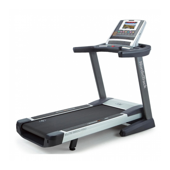
NordicTrack ELITE 9500 PRO User Manual
Ntl170100
Hide thumbs
Also See for ELITE 9500 PRO:
- User manual (44 pages) ,
- User manual (40 pages) ,
- User manual (40 pages)
Table of Contents
Advertisement
www,nordictrack.com
Model No. NTL17010.0
Serial No.
Write the serial number in the space
above for reference.
Serial Number
Decal
QUESTIONS?
If you have questions, or if parts are
damaged or missing, DO NOT CON-
TACT THE STORE; please contact
Customer Care.
IMPORTANT: Please register this
product (see the limited warranty
on the back cover of this manual)
before contacting Customer Care.
CALL TOLL-FREE:
1-800-TO-BE-FIT
(1-800-862-3348)
Mon.-Fri,
6 a.m.-6 p.m. MT
Sat. 8 a.m.-4 p.m. MT
ON THE WEB:
www.nordictrackservice.com
USER'S
A
IAL
Advertisement
Table of Contents

Related Manuals for NordicTrack ELITE 9500 PRO


Summary of Contents for NordicTrack ELITE 9500 PRO
- Page 1 Model No. NTL17010.0 USER'S Serial No. Write the serial number in the space above for reference. Serial Number Decal QUESTIONS? If you have questions, or if parts are damaged or missing, DO NOT CON- TACT THE STORE; please contact Customer Care.
- Page 2 *Keep cloth rig, FROM THISAREA WHILE THE gnge[s, and hair TREADMILL I SINOPERATION..Never b_/to adjust or fix the belt while _tis moving. athletic shoes while I_]_ .Always wea_ operating treadmill. NordicTrack is a registered trademark of ICON IP, Inc.
- Page 3 14. To purchase a surge suppressor, informed of all warnings and precautions. your local NordicTrack dealer or call the tele= phone number on the front cover of this man- Use the treadmill only as described. ual and order part number 146148, or see your local electronics store.
- Page 4 20. Never leave the treadmill unattended while it inspect and properly tighten all parts of the is running. Always remove the key, unplug treadmill regularly. the power cord, and press the power switch DANG ER: A ways onp ug the power into the off position when the treadmill is not in use.
- Page 5 BEFORE YOU BEGIN Thank you for selecting the revolutionary NordicTrack ® ing this manual, please see the front cover of this man- ELITE 9500 PRO treadmill. The ELITE 9500 PRO ual. To help us assist you, please note the product treadmill offers an impressive selection of features de- model number and serial number before contacting us.
- Page 6 ASSEMBLY Assembly requires two persons. Set the treadmill in a cleared area and remove all packing materials. Do not dispose of the packing materials until assembly is completed. Note: The underside of the treadmill walking belt is coated with high-performance lubricant.
- Page 7 PulltheUpright W ire(84)andtheBaseGround Wire(94)through theindicated holeintheBase (97). Attach theBaseGround Wire(94)totheBase (97)witha #8x 1/2"Ground Screw(9). Hole Identify the Left Upright (89), which is marked with a "Left" sticker. Have a second person hold the Left Upright near the Base (97). See the inset drawing. Tie the wire tie in the Left Upright (89) securely around the end of the Upright Wire (84).
- Page 8 Identify theLeftBaseCover(92)andtheRight BaseCover(93).SlidetheLeftBaseCover o nto theLeftUpright ( 89).Slidethe Right B aseCover ontotheRightUpright ( 90).Do not pressthe BaseCoversinto placeyet. Set the handrail assembly face down on a soft surface to avoid scratching the handrail assem- bly. Remove two 3/8" x 2" Bolts (3) and a Handrail Bracket (85) from each side of the handrail as- sembly.
- Page 9 Remove the four 3/8" x 1" Bolts (2) from the Uprights (89, 90). Long Orient each Handrail Bracket (85) so that the long tab is in the position shown and the large holes are on top. Route the Upright Wire (84) Large Holes through the center hole in the Handrail Bracket.
- Page 10 Insert the wires into the Left Upright (89) as you set the handrail assembly on the Left Upright Handrail and the Right Upright (90). Be careful not to Assembly pinch the wires. Wires Attach the handrail assembly with the four 3/8" x 2"...
- Page 11 11. Firmly tighten the four 3/8" x 2 3/4" Bolts (7) and the four 3/8" x 1 1/4" Bolts (8) (only one side is shown). Press the Left Base Cover (92) and the Right Base Cover (93) onto the Base (97) until they snap into place.
- Page 12 14. Remove the packaging material from the bottom of the Frame (56). See the inset drawing. Make sure that the 1/2" Rear Foot Nuts (30) are threaded all the way onto the Rear Feet (60). Turn the two Rear Feet all the way into the Frame.
- Page 13 HOW TO USE THE CHEST PULSE SENSOR HOW TO PUT ON THE CHEST PULSE SENSOR may remain activated longer than necessary, drain- ing the battery prematurely. The chest pulse sensor consists of two components: the chest strap and the sensor unit. Insert the tab on o Store the chest pulse sensor in a warm, dry place.
- Page 14 OPERATION AND ADJUSTMENT THE PRE-LUBRICATED WALKING BELT dance with all local codes and ordinances. IMPORTANT: The treadmill is not compatible with The treadmill features a walking belt coated with high- GFCI-equipped outlets and may not be compatible performance lubricant. IMPORTANT: Never apply sil- with AFCI-equipped outlets.
- Page 15 CONSOLEDIAGRAM 5T6_/J\'CC_NE _5TEPSPEED ST_P DECUN_ FEATURES OF THE CONSOLE You can even listen to your favorite workout music or audio books with the console's stereo sound system The treadmill console offers an impressive array of while you exercise. features designed to make your workouts more effec- tive and enjoyable.
- Page 16 HOW TO TURN ON THE POWER HOW TO USE THE QUICK START WIZARD iMPORTANT: if the treadmill has been exposed to The first time you turn on the treadmill, the console will cold temperatures, allow it to warm to room tem- prompt you to set up your wireless connection and perature before turning...
- Page 17 HOW TO USE THE MANUAL MODE The browser will open to the iFit.com registration page. Enter a username and password and your e- mail address. Enter the activation code from the Insert the key into the console. iFit Live flier that came with the treadmill. Touch the Place of Purchase drop-down menu for a list of See HOW TO TURN ON THE POWER on page options.
- Page 18 Change the incline of the treadmill as desired. - Your pace in minutes per mile To change the incline of the treadmill, press the Your heart rate (see Incline increase and decrease buttons or one of the step 6 on page 19). numbered 1 Step Incline buttons.
- Page 19 Measure your heart rate if desired. speed of the fan will automatically increase and de- crease as the speed of the walking belt increases and decreases. Note: If you use the handgrip pulse sensor and the chest pulse sensor at the same time, the Press the Manual fan console will not display your heart rate accu- rately.
- Page 20 HOW TO USE AN ONBOARD WORKOUT and/or incline setting may be programmed for con- secutive segments. Insert the key into the console. During the workout, the profile will show your See step 1 on page 17. progress. Touch the Display increase and de- crease buttons repeatedly to view the profile.
- Page 21 HOW TO USE AN IFIT LIVE WORKOUT Note: The calorie goal is an estimate of the number of calories that you will burn during the workout. The actual number of calories that Note: To use an iFit Live workout, you must have ac- you burn will depend on your weight, in addi- cess to a wireless network including an 802.1 lb/n...
- Page 22 When you select an iFit Live workout, the screen separation distance of at least 20 cm from all per- will show the name, duration, and distance of the sons and must not be co-located or operating workout. The screen will also show the approxi- conjunction with any other antenna or transmitter.
- Page 23 HOW TO USE THE INTERNET BROWSER you wish to search for, and touch the Done button. Touch the arrow buttons to view each instance of the text. Touch the X button to close the search box. To open the browser, touch the Globe button in the lower left corner of the screen.
- Page 24 HOW TO USE THE SETTINGS MODE to connect to the network. Touch the Cancel button to return to the list of networks. If the network has a The console features a settings mode that allows you password, touch the password entry box. A key- to connect the treadmill to your own wireless network board will appear on the screen.
- Page 25 Log in to your iFit Live account. Turn on or turn off the display demo mode. To view user accounts, touch the iFit Live Login The console features a display demo mode, de- button. Then, enter your user name and password signed to be used if the treadmill is displayed in a store.
- Page 26 HOW TO USE THE MAINTENANCE MODE cline system. Touch the Begin button to calibrate the incline system or the Cancel button to return to The console features a maintenance mode that allows the maintenance mode. When the incline system is calibrated, touch the Finish button.
- Page 27 Update the console firmware. Using a pencil eraser or other small object, touch the center of the target. Then, touch the rest of the For the best results, regularly check for targets. After several seconds, the console will exit the calibration mode. firmware updates.
- Page 28 HOW TO USE THE STEREO SOUND SYSTEM HOW TO ADJUST THE CUSHiONiNG SYSTEM To play music or audio books through the console's Remove the key from the console and unplug the speakers, you must connect your MP3 player, CD power cord. The treadmill features a cushioning sys- player, or other personal audio player to the console.
- Page 29 HOW TO FOLD AND MOVE THE TREADMILL HOW TO FOLD THE TREADMILL HOW TO MOVE THE TREADMILL To avoid damaging the treadmill, adjust the incline Before moving the treadmill, fold it as described at the left. CAUTION: Make sure that the latch knob is to zero percent before you fold the treadmill.
- Page 30 TROUBLESHOOTING Most treadmill problems can be solved by following the simple steps below. Find the symptom that applies, and follow the steps listed, if further assistance is needed, see the front cover of this manual. PROBLEM: The power does not turn on SOLUTION: a.
- Page 31 Lower the treadmill (see HOW TO LOWER THE TREADMILL FOR USE on page 29). Remove the three #8 x 3/4" Screws (1). Carefully pivot the Motor Hood (71) off. Locate the Reed Switch (52) and the Magnet (50) on the left side of the Pulley (49). Turn the Pulley View until the Magnet is aligned with the Reed Switch.
- Page 32 PROBLEM: The walking belt is off-center or slips when walked on SOLUTION: a. If the walking belt is off-center, first remove the key and UNPLUG THE POWER CORD. If the walking belt has shifted to the left, use the hex key to turn the left idler roller bolt clockwise 1/2 of a turn;...
- Page 33 EXERCISE GUiDELiNES Burning Fat--To burn fat effectively, you must exer- , WARNING: Before beginning this cise at a low intensity level for a sustained period of time. During the first few minutes of exercise, your or any exercise program, consult your physi- body uses carbohydrate calories for energy.
- Page 34 PART LIST Model No. NTL17010.0 Rll10A To locate the parts listed below, see the EXPLODED DRAWING near the end of this manual. Key No. Qty. Description Key No. Qty. Description #8 x 3/4" Screw Reed Switch Clamp 3/8" x 1" Bolt Reed Switch 3/8"...
- Page 35 Key No. Qty. Description Key No. Qty. Description Wheel Handrail Frame Handrail Top Pulse Bar Top Console Pulse Ground Wire Cushion Adjust Assembly #1 Front Cushion Cushion Adjust Assembly #2 5/16" Cushion Washer Hex Key User's Manual Note: Specifications are subject to change without notice. For information about ordering replacement parts, see the back cover of this manual.
- Page 36 r" 1108 35_i i 42 "4...
- Page 37 EXPLODED DRAWING Model No. NTL17010.0 Rll10A...
- Page 38 EXPLODED DRAWING Model No. NTL17010.0 Rll10A -..-.., -.,.-_.. i ":"-"'- 98 '_13 _--34...
- Page 39 EXPLODED DRAWING Model No. NTL17010.0 Rll10A °7 .-:jl 12-4...
- Page 40 ORDERING REPLACEMENT PARTS To order replacement parts, please see the front cover of this manual. To help us assist you, be prepared to pro- vide the following information when contacting us: o the model number and serial number of the product (see the front cover of this manual) o the name of the product (see the front cover of this manual) o the key number and description of the replacement part(s) (see the PART LIST and the EXPLODED DRAWING near the end of this manual)