Table of Contents
Advertisement
Quick Links
Product May Vary Slightly From Pictured.
CAUTION:
Weight on this product should not exceed 250 lbs.
This Product is Distributed Exclusively by
2040 N. Alliance, Springfield, MO 65803
www.staminaproducts.com
Customer Care
1 (800) 375-7520
Owner's
Manual
WARNING
!
Exercise can present a
h e a l t h r i s k . C o n s u l t a
physician before beginning
any exercise program with
this equipment. If you feel
faint or dizzy, immediately
d i s c o n t i n u e u s e o f t h i s
equipment. Serious bodily
i n j u r y c a n o c c u r i f t h i s
equipment is not assembled
and used correctly. Serious
bodily injury can also occur
if all instructions are not
followed. Keep others and
pets away from equipment
when in use. Always make
sure all bolts and nuts are
securely tightened prior to
each use. Follow all safety
instructions in this manual.
When calling for parts or
service, please specify
the following number :
Model#: 20-4800A
STAMINA PRODUCTS
MADE IN CHINA
©
2015 Stamina Products, Inc.
2017, 04
Advertisement
Table of Contents

Related Manuals for Stamina inLine 20-4800A


Summary of Contents for Stamina inLine 20-4800A
- Page 1 CAUTION: Weight on this product should not exceed 250 lbs. This Product is Distributed Exclusively by STAMINA PRODUCTS MADE IN CHINA 2040 N. Alliance, Springfield, MO 65803 Customer Care © 2015 Stamina Products, Inc. 1 (800) 375-7520 2017, 04 www.staminaproducts.com...
-
Page 2: Table Of Contents
TABLE OF CONTENTS Safety Instructions ........2 Storage ............15 Before You Begin ........4 Maintenance ..........15 Equipment Warning, Caution & Notice Labels ... 5 Product Parts Drawing ......16 Hardware Identification Chart ....6 Parts List ............ 17 Assembly Instructions ........ - Page 3 1 (800) 375-7520 customer.care@staminaproducts.com Hi! From all of us here at Stamina Products, thank you for your purchase. We know that you have big fitness goals in mind and we are here to help you along. Call us, email us, or send us a message on Facebook. Be sure to contact us if you have any questions on your new product.
-
Page 4: Before You Begin
BEFORE YOU BEGIN Thank you for choosing the inLine® Traction Although Stamina constructs its products with Control System. We take great pride in producing the finest materials and uses the highest standards this quality product and hope it will provide many... -
Page 5: Equipment Warning, Caution & Notice Labels
EQUIPMENT WARNING, CAUTION & NOTICE LABELS This chart is provided to help identify the warning, caution, and notice labels on the inLine® Traction Control System. Please take a moment to familiarize yourself with all of the warning, caution, and notice labels. Label is larger than actual size CAUTION LABEL(38) CAUTION... -
Page 6: Hardware Identification Chart
HARDWARE IDENTIFICATION CHART This chart is provided to help identify the hardware used in the assembly process. Place the washers or the ends of the bolts or screws on the circles to check for the correct diameter. Use the small scale to check the length of the bolts and screws. -
Page 7: Assembly Instructions
ASSEMBLY INSTRUCTIONS Place all parts from the box in a cleared area and position them on the floor in front of you. Remove all packing materials from your area and place them back into the box. Do not dispose of the packing materials until assembly is completed. - Page 8 ASSEMBLY INSTRUCTIONS STEP 3 Attach the REAR SUPPORT(10) to the FRONT SUPPORT(2) with BUTTON HEAD BOLT (M10x1.5x95mm)(29), WASHERS(M10)(34), and NYLOCK NUT(M10x1.5)(31). STEP 4 Attach the INNER TUBE(43) to the MAIN FRAME(14) with BUTTON HEAD BOLT(M10x1.5x95mm)(29), WASHERS(M10)(34), and NYLOCK NUT(M10x1.5)(31).
- Page 9 ASSEMBLY INSTRUCTIONS STEP 5 Attach the SWING ARM(8) to the MAIN FRAME(14) with BUTTON HEAD BOLT(M10x1.5x125mm)(30), WASHERS(M10)(34), and NYLOCK NUT(M10x1.5)(31). STEP 6 Insert the HANDLEBAR(5) into the SWING ARM(8) and secure with BUTTON HEAD BOLTS (M8x1.25x15mm)(27), and ARC WASHERS(M8)(35).
- Page 10 ASSEMBLY INSTRUCTIONS STEP 7 Attach the CUSHION(6) to the SWING ARM(8) with the LOCKING KNOBS(9). STEP 8 Insert the LEFT and RIGHT ARM PAD TUBES(3, 4) into both sides of the SWING ARM(8) and lock in position with the ADJUSTMENT KNOB(7). NOTE: The pin of the ADJUSTMENT KNOBS(7) must be inserted into one of the adjustment holes in the LEFT and RIGHT ARM PAD TUBES(3, 4) and use the same adjustment hole position on both sides.
- Page 11 ASSEMBLY INSTRUCTIONS STEP 9 Refer to the illustration below. Position the BELT(25) with its two ends to the outside. Install the BELT(25) by attaching the TRIANGLE HOOKS(19) to the MAIN FRAME(14) with BUTTON HEAD BOLTS(M8x1.25x15mm)(27). End of belt End of belt...
-
Page 12: Operational Instructions
OPERATIONAL INSTRUCTIONS To use the inLine® Traction Control System, proper set up and adjustment of the inLine® Traction Control System is important for a revitalizing stretch. HEIGHT ADJUSTMENT Pivot of the BELT(25). Refer to illustration A. The proper height of the inLine®... - Page 13 OPERATIONAL INSTRUCTIONS ARM PAD(20) ADJUSTMENT The width between the two ARM PADS(20) must be adjusted properly to fit the width of your upper body. The back of your upper arms should rest on the ARM PADS(20) during use. To adjust, remove the ADJUSTMENT KNOBS(7) and slid the LEFT and RIGHT ARM TUBES(3, 4) to the desired position.
- Page 14 OPERATIONAL INSTRUCTIONS CAUTION: Keep both feet flat on the ground while stretching. Exercise within your limits. If you feel faint or dizzy, immediately discontinue use of this equipment. STEP ONE: Adjust the height, rollers and waist belt as described on pages 12 and 13.
-
Page 15: Storage
1. Verify that all nuts and bolts are present and properly tightened. Replace missing nuts and bolts. Tighten loose nuts and bolts. 2. Verify that the CAUTION LABEL(38) is in place and easy to read. Call Stamina Products immediately at 1-800-375-7520 for a replacement CAUTION LABEL(38) if it is missing or damaged. -
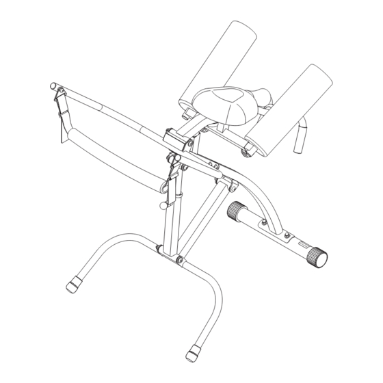
Page 16: Product Parts Drawing
PRODUCT PARTS DRAWING FRONT BACK... -
Page 17: Parts List
PARTS LIST PART# PART NAME Front Stabilizer Front Support Right Arm Pad Tube Left Arm Pad Tube Handlebar Cushion Adjustment Knob Swing Arm Locking Knob Rear Support Spring Pin Main Frame Foam Roller Buckle Bumper Bushing Triangle Hook Arm Pad Flange Plug (ø25.4mm) Round Plug (ø25.4mm) Endcap (ø50.8mm) -
Page 18: Warranty
To implement this limited warranty, send a written notice stating your name, date, and place of purchase and a brief description of the defect along with your receipt to Stamina Products, Inc. P.O. Box 1071, Springfield Missouri, USA, 65801-1071, or email us at customer.care@staminaproducts.com, or call us at 1-800-375-7520. -
Page 19: Fax/Mail Ordering Form
P.O. Box 1071 Springfield, MO. 65801-1071 Would you like to recieve email information or special offers from Stamina Products? Register at contact.staminaproducts.com TO REGISTER YOUR PRODUCT To enact your warranty, please register your product by going to register.staminaproducts.com. Please have your product model number (printed on the cover of this owner’s manual) and the serial number (printed on the black and white sticker on your...