Panasonic DP-150 Service Manual
Hide thumbs
Also See for DP-150:
- Operating instructions manual (114 pages) ,
- Specifications (2 pages) ,
- User manual (105 pages)
Chapters
Table of Contents

Related Manuals for Panasonic DP-150


Summary of Contents for Panasonic DP-150
- Page 1 Service Manual Digital Copier DP-150 Service Manual Section DP-150 Parts Manual Section DP-150 © 2000 Matsushita Graphic Communication Systems, Inc. All rights reserved. Unauthorized copying and distribution is a violation of law.
-
Page 2: Table Of Contents
DP-150 Table of Contents WARNING Section I General Description Specifications ................Features ..................New Functions ................Systems ..................Control Panel ................. Component Location ..............1. Outer View ................. 2. Inner View .................. 3. Fan/ Motor Location ..............4. Sensor Location ................. - Page 3 Section III Maintenance Precautions for Preventive Maintenance Service ......Maintenance Chart ................ Cleaning Method ................Disassembly and Re-assembly ............. 1. Sheet Bypass ................2. Developer Unit/Drum unit ............3-13 3. Fuser Unit ................3-18 4. Optics Unit ................3-21 5. Main Body ................3-27 Adjustment ...................
- Page 4 This manual was developed and is supplied to authorized servicing dealers by Panasonic Co. for the sole purpose of providing information necessary for the equipment’s proper support. It is intended that this information be confidential and may not be reproduced without prior written consent from Panasonic Co.
- Page 5 For U.S.A For your safety Caution This product utilizes a laser. Use of controls or adjustments or performance of procedures other than those specified herein may result in hazardous radiation exposure. DANGER-Invisible laser Product complies with DHHS Rules 21 radiation when open and CFR Subchapter J in effect of date interlock defeated.
- Page 6 For your safety Caution This product utilizes a laser. Use of controls or adjustments or performance of procedures other than those specified herein may result in hazardous radiation exposure. ATTENTION : PELIGRO : Rayonnement laser invisible Cuando se abre y se invalida el bloqueo, se dangereux en cas d'ouverture et producen radiaciones invisibles de laser.
- Page 7 Caution: Danger of explosion if battery is incorrectly replaced. Replace only with the same or equivalent type recommended by the manufacturer. Dispose of used batteries according to the manufacturer’s instructions. For Sweden, and Denmark VARNING! Explosionsfara vid felaktigt batteribyte. Använd samma batterityp eller ekvivalent typ som rekommenderas av apparattillverkaren.
- Page 8 If you lose the fuse cover the plug must not be used until a replacement cover is obtained. A replacement fuse cover can be purchased from your local Panasonic Dealer. IF THE FITTED MOULDED PLUG IS UNSUITABLE FOR THE SOCKET OUTLET IN YOUR OFFICE THEN THE FUSE SHOULD BE REMOVED AND THE PLUG CUT OFF AND DISPOSED OF SAFELY.
-
Page 9: Section I General Description
Section I General Description 1. 1 Specifications <General Specifications> Type: Desk top (scanner and printer) Copy Process: Laser recording method + Electrostatic photographic method Development Process: Mono-component Image Control: Digital control Photoreceptor: Fusing System: Heat and Pressure Maximum Copy Size: Legal (8.5"... - Page 10 <Copy specifications> Resolution: 600 dpi Gradation: 256 steps (photo mode) First Copy Time: 7.9 sec. (LETTER R/A4R: manual exposure) Ratios: Enlargement (fixed ratio) : 1.29 (For North America) 1.41 (Except North America) Reduction (fixed ratio) : 0.79, 0.65, 0.61 (For North America) 0.87, 0.82, 0.71 (Except North America) Zoom :...
-
Page 11: Features
1. 2 Features 1. Advanced digital technology 1) This copier uses advanced digital technology to ensure high reliability and offers such advanced functions as toner save. 2. Quick operation First copy time of 7.9 seconds. 1. 3 New Functions 1. Toner save mode This feature unable you to get higher copy yield on your toner save mode. -
Page 12: Systems
1. 4 Systems Control panel Open/close Right Cover Front Cover Sheet Bypass Paper Tray... -
Page 13: Control Panel
1. 5 Control Panel • DP-150 Energy Saver Key Clear/Stop Display Auto/Photo Select Key ENERGY CLEAR/STOP 141% SAVER 100% PHOTO AUTO FLS¥B4 A4 FP-D150FP START ZOOM FLS¥B4 A5 DARK (50~200%) LIGHT Exposure control Select Paper Zoom Start Key Tray Key... -
Page 14: Component Location
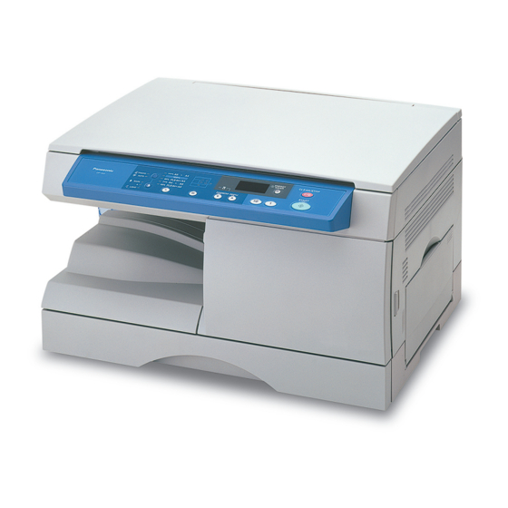
1. 6 Component Location 1. Outer View Control Panel Right Cover Front Cover Paper Tray Sheet Bypass 2. Inner View Heat Roller Pressure Roller Drum Transfer Roller Sheet Bypass Pick-up Roller Paper Feed Roller Registration Sheet Bypass Sheet Bypass Roller DFP Roller Feed Roller... -
Page 15: Fan/Motor Location
3. Fan/Motor Location Optics Drive Motor Exhaust Fan Main Motor 4. Sensor Location Optics Home Position Paper Tray Paper Exit Paper Pass Size Detection Toner Level... -
Page 16: Solenoid/Switch Location
5. Solenoid/Switch Location Paper Feed Solenoid Registration Solenoid Power Switch Sheet Bypass Solenoid 6. PCB Location Lamp Inverter Main CPU Control Panel High Voltage Power Supply (HVPS) LVPS & Discharge LED... -
Page 17: Copy Process
1. 7 Copy Process Paper exit Original –DC (7) Discharge (5) Fusing (1) Primary charge (6) Cleaning (2) Image exposure Photoelectric conversion (4) Separation (4) Transfer Toner (3) Developing Paper feed Primary Charge: Image Exposure: Developing: Toner Illumination Charge corona Drum Drum Latent... -
Page 18: Precautions For Consumables
1. 8 Precautions for Consumables (1) Photoreceptor drum • Do not touch the surface of the drum with your hands. • Stand the drum with the drum gear up for storage. • Be careful not to put water, oil, saliva and/or dirt on the drum. •... -
Page 19: Section Ii Mechanism
Section II Mechanism 2. 1 Main Drive The driving mechanism of the machine is as follows. Main motor Paper exit drive gear Fuser drive gear Paper Developer feed coupling drive gear Developer drive gear Motor name Driving method Driving unit •... -
Page 20: Operations
2. 2 Operations 1.Sheet Bypass 1)Construction of the sheet bypass • Sheet bypass consists of a sheet bypass paper feed unit and a registration roller unit. Component name Description Sheet bypass paper feed Feed the paper from the sheet bypass pick up roller roller to the registration roller. - Page 21 2)Operation of the sheet bypass paper feed unit • When starting copying with the sheet bypass selected, the rotation of the main motor is transmitted to the transmission gear via drive gears and to the registration roller gear in the sheet bypass paper feed unit. The rotation of the registration roller gear is transmitted to the sheet bypass solenoid via middle roller.
-
Page 22: Paper Feed Unit
4)Sheet bypass paper size detection • The paper size detecting micro switchs are attached to the sheet bypass and detect the paper size. Micro switchs 2.Paper Feed Unit 1)Construction of the paper feed unit • The composition is as follows. Component name Description Paper feed roller... - Page 23 2)Operation of the paper feed tray • The paper tray sensor detects the paper tray is properly postioned in the copier. • The spring under the bottom plate of the tray then lifts paper. • With the Start key, the main motor starts rotating and transmits the rotation to the middle gear via drive gears.
-
Page 24: Toner Cartridge
3.Toner Cartridge 1)Construction of the Toner Cartridge • The developer unit consists of the magnet roller, agitator 1 and agitator 2. • Toner is mixed by the agitator 1 and 2, then transported onto the developer sleeve. Toner on the developer sleeve adheres to the electrostatic latent image on the drum by AC bias for development. - Page 25 2)Driving developer • The rotation of the main motor is transmitted to the developer drive gear via some gears. The developer unit is connected to the machine with gears and linked with the mixing mill gear and transport screw gear to mix and transport toner. The transport screw coupling is linked with the waste toner screw to collect waste toner.
- Page 26 3)Cleaning drum • The toner remaining on the drum is scraped off by the cleaning blade after the development and transfer. • The cleaning blade is fixed and pressed on the drum surface to remove the toner on the surface. •...
-
Page 27: Fuser Unit
4.Fuser Unit 1)Construction of the fuser unit • The composition is as follows. Component name Description Heat roller Fuse toner onto paper by heat. (Aluminum + Teflon coating) Pressure roller Fuse toner onto paper by pressing paper to the heat roller. - Page 28 2)Fusing The heat roller and the pressure roller in the fuser unit melt toner onto the paper using a combination of heat and pressure. • The upper heat roller has a Teflon coating on the aluminum surface, which allows toner easily to be released from the surface. The ruggedness enhancement and antistatic prevention processing are used in making the heat roller.
- Page 29 3)Driving the fuser unit • The rotation of the main motor is transmitted to the heat roller gear via some gears. • The paper exit sensor lever detects the paper exiting the fuser unit. 4)Fusing the temperature The heat roller has a halogen lamp that lights up while warming up and making copies.
-
Page 30: Optics Unit
5.Optics Unit 1)Construction of the optics unit • The optics unit consists of the exposure (fluorescent) lamp, the lens, the CCD sensor and the reflecting mirrors. • The optics motor moves the full-speed unit exposing the original with the exposure lamp. The reflection from the original is gathered on the CCD image sensor via lens, where optics signals can be converted into electrical signals. - Page 31 2)Photoelectric conversion • Photoelectric conversion is to convert optical signals into electrical signals. Pixel used for photoelectric conversion is called “photoelectric converted pixel”. The linear type of CCD image sensor for B/W is used here. 3)CCD sensor The CCD image sensor consists of the photo acceptance unit, transfer unit and output unit.
- Page 32 5)Driving the optics unit • The optics unit (full-speed and half speed unit) is driven by the optics unit motor. Its rotation is transmitted to the full-speed and half-speed unit via optics drive belt, optics drive pulley, full-speed unit drive wire and half-speed unit drive wire. •...
-
Page 33: Laser Unit
6.Laser Unit (1) General description Synchronized Semiconductor laser sensor Collimator lens Mirror Lens Polygon mirror Main-scanning direction OPC photoreceptor Mirror Sub-scanning direction 1)The image photoelectric-converted by the CCD sensor is converted into laser intensity signals by the CPU PCB and laser control PCB, and the signals are output according to the write timing signals. - Page 34 (2) Semiconductor laser 1)The laser beam is switched ON/OFF with or without the electric current on the two semiconductor lasers. This “ON/OFF” is based on the digital signals corresponding to the image data and the beam is emitted onto the drum to form the image. (Letter “P”...
- Page 35 (5) f-θ lens 1)The parallel beams reflected by the polygon scanner are gathered on the drum by f-θ lens. This lens is designed to bend the transmitted beams strongly toward the optic axis around the lens whose scanning angle is large. f-θ...
-
Page 36: Section Iii Maintenance
Section III Maintenance Machine cleaning and parts replacements are the main purpose of the periodic maintenance service. It is essential for service to perform the maintenance properly to ensure the customer's satisfaction. This service makes it possible to achieve good machine performance. - Page 37 3) Precautions for disassembly and adjustment • Unplug the power before disassembling the machine. • Do not operate the machine with the parts removed. Be careful not to have your clothes caught in the gears, belts and so on when you need to operate the machine without covers.
-
Page 38: Maintenance Chart
3.2 Maintenance chart 1) Replacement Item Part Part number Maintenance Remarks 100k 200k Main unit Ozone filter FFPHJ0057 LSU cover glass –––––––– Transfer unit Transfer roller FFPMA0677 Discharge needle FFPKS1254 Fuser unit Heat roller FFPMA0689 Pressure roller FFPMA06901 Pressure roller bushing FFPMQ0652 Heat roller bushing FFPMQ0653... -
Page 39: Cleaning Method
3.3 Cleaning Method Proceed to next page. Heat Roller Pressure Roller Drum Transfer Roller Sheet Bypass Pick-up Roller Paper feed Roller Registration Sheet Bypass Sheet Bypass Roller DFP Roller Feed Roller... - Page 40 Cleaning position Tool/solvent Description/precaution 1 Sheet bypass pick up •Use of IPA (isopropyl alcohol) must Dampened be minimized. cloth/IPA roller •Avoid using cotton. 2 Sheet bypass paper feed roller 3 Registration roller 4 Transport roller 5 Paper feed roller (Tray) 6 Corona wire Dampened •High voltage leak may occur unless...
- Page 41 Cleaning position Tool/solvent Description/precaution 15 Toner level sensor Cloth 16 Platen glass 17 Platen mat Cloth 18 Ozone filter • In a dusty place, clogging and jamming may occur before the machine reaches the defined replacement term. 19 Outer cover •...
-
Page 42: Disassembly And Re-Assembly
3.4 Disassembly and Re-assembly PM parts replacement procedure • The replacement procedure is shown below. Fuser unit Optics unit Developer unit Drum unit Paper Tray Sheet Bypass... -
Page 43: Sheet Bypass
1. Sheet bypass Item Part name Sheet bypass pick-up roller Sheet bypass Paper feed paper feed roller unit Sheet bypass DFP roller Registration roller 1) Replacement of the sheet bypass pick-up roller/sheet bypass paper feed roller Open the right cover. Remove the sheet bypass paper feed unit cover with the screw driver. - Page 44 2) Replacement of the registration roller/registration roller bushing Open the right cover. Take out the toner cartridge. Lock Knob Take out the drum unit. Remove the registration roller cover. Toner Cartridge Toner Cartridge Drum Unit Registration Roller Cover...
- Page 45 Remove the Main motor. Remove E rings. Main motor E Ring Remove the E rings. (front/rear) Move the bushing upside. Remove the registration roller. Registration Roller 3-10...
- Page 46 3) Replacement of the paper feed roller Remove the toner cartridge. Remove the drum unit. Lock Knob Toner Cartridge Toner Cartridge Drum Unit Tilt the unit. NOTE: Remove platen cover first. 3-11...
- Page 47 Replace the paper feed roller. Paper feed Roller 3-12...
-
Page 48: Developer Unit/Drum Unit
2. Developer unit/Drum unit Item Part name Cleaning blade Drum Blade side seal (F) Blade side seal (R) Corona Developer unit Corona wire Toner cartridge 7 Developer blade Magnet roller 9 Magnet roller support (R) 10 Toner receiving sheet 11 Toner receiver support mylar 3-13... - Page 49 1) Replacement of the drum/cleaning blade/blade side seal Open the front cover. Open the right cover. Lock Knob Take out the toner cartridge. Take out the drum unit. Toner Cartridge Toner Cartridge Drum Unit 3-14...
- Page 50 Remove the drum coupling F and R. Drum Coupling (Turn them until they click.) Rear Remove the drum. Drum Coupling Front Remove the blade fixing screw. Remove the corona. Gear Cover (1 screw) Corona 3-15...
- Page 51 Remove the blade. Side Seal Rear Remove the side seals. Side Seal Front Blade 2) Replacement of the corona wire. Perform the procedure 1. Remove the corona fixing screw. Pull out the corona. Remove the corona grid (3a)and terminal cover (3b). Terminal Cover Grid...
- Page 52 3) Replacement of the side seal. Take out the developer cartridge. Toner Cartridge Remove the cartridge rear cover. Cartridge Rear Cover Remove the magnet roller. Replace the side seal. Magnetic roller 3-17...
-
Page 53: Fuser Unit
3. Fuser unit Item Part name Fuser lamp Heat roller Heat roller shaft Bushing Heat roller gear Fuser unit Thermistor Separation finger Pressure roller Pressure roller shaft 3-18... - Page 54 1) Replacement of the fuser lamp/heat roller/bushing/heat roller gear Turn OFF/unplug the power. Open the front cover. Open the right cover. Remove the rear cover. (3 screws) Remove the lamp/thermistor relay connectors. Remove the screws on the fuser unit. (2 screws) Paper Feed Unit Cover Remove the pressure unit.
- Page 55 2) Replacement of the thermistor. Perform procedure 2. Remove the screws. Replace the thermistor. Thermistor Thermostat 3) Replacement of the separation finger. Perform procedure 2. Separation Finger Remove the separation finger springs. Replace the three fingers. Finger Spring 4) Replacement of the pressure roller/pressure roller bushing. Perform procedure 2.
-
Page 56: Optics Unit
4. Optics unit Item Part name Exposure lamp Optics unit 3 Motor 4 Lens 5 Optics drive pully 1) Replacement of exposure lamp/LSU Upper Left Enter the Service mode. Cover Perform “F8-C00”. Remove the upper right cover. Remove the platen cover. Upper Right Cover Rear Cover Platen Cover... - Page 57 Remove the full-speed unit. Replace the exposure lamp. When assembling the unit: Place the half-speed unit in the middle and the full-speed unit on the right, and then fix the optics wire. Lamp Unit Exposure Lamp 3-22...
- Page 58 2) Replace the LSU (Laser Scaner Unit) Enter the service mode, and perform F8-C00. Remove the right upper cover. Remove the left and right cover. Remove the rear cover. Remove the platen cover. Remove 2 screws. Remove the control panel. (2 screws, 1 connector) Remove the CPU shield plate.
- Page 59 Remove the optics unit assembly. (7 screws) Remove the cable from the paper exit guide assembly. Remove the paper exit guide assembly. Remove the LSU assembly. (4 screws) 3-24...
- Page 60 3) Replace the CCD PCB Remove the lens unit cover. Replace the CCD PCB. Adjust the copier image with adjusting screws. 3-25...
- Page 61 4) Replacement of the CPU PCB When replacing the CPU PCB, pay attention to the connections of CN20 and CN21. CN21 Connect the lead wire connector labeled CN20 to CN20. CN20 Connect the lead wire connector without a label to CN21. CN20 labeled 5) Replacement of the LVPS...
-
Page 62: Main Body
5. Main body Item Part name 1 Ozone filter 1 Main body Transfer roller Discharge lamp 1) Replacement of the transfer roller and Discharge lamp Open the right cover. Remove the transfer roller releasing its fingers. Remove the developer unit. Remove the drum. -
Page 63: Adjustment
3.5 Adjustment 3-28... -
Page 64: Exposure Adjustment
1. Exposure adjustment Figure Procedure Image density adjustment Make sure that "F6-C17, C19" is “0". Text/Photo mode Confirm the image with the mode. (The exposure is at the center in the manual mode and the text/photo mode.) Invisible When copying the gray scale (P/N FQ-SJ101), 1 must be invisible. -
Page 65: Skew/Side Position Adjustment (Printer Unit)
2. Skew/Side position adjustment (Print unit) Position Adjustment Skew adjustment When the skew copy is not fixed by the tray adjustment, follow the instruction below. Load LETTER/A4 paper in the sheet bypass. Enter in the service mode. Select the "F8-C50" mode and press Start key. -
Page 66: Skew/Lead Edge Position Adjustment (Scanner Unit)
3. Skew/Lead edge position adjustment (Scanner unit) Position Adjustment Attention: The CCD unit should be adjusted ONLY WHEN the printer fails to adjust it. Image skew adjustment Before loosening the CCD fixing screw (front), put a mark on the position where (Original) the CCD is installed. -
Page 67: Updating The Firmware
(F9-C01). Turn the power switch OFF. Remove the rear cover. Insert the Flash ROM Card into the copier card slot.(Panasonic logo side should be forwarded) Turn the power switch ON. Remove the Flash ROM card after copier warming up is completed. -
Page 68: Glossary Of Electrical Abbreviations
Section IV PCB Connector and Signal Imformation 4. 1 Glossary of Electrica Abbreviations Signal Name Function AC 120V / AC 220 - 240V power supply AC 120V / AC 220 - 240V power supply AGND Ground BREF Bias adjustment signal Discharge lamp ON/OFF signal ENABLE Laser current cintrol signal... - Page 69 Signal Name Function PFOSN Paper exit sensor paper detecting signal PGND Ground PMCLK Polygon motor lock detecting signal PMCNT Polygon motor drive control signal PMLCK Polygon motor drive clock signal PUSOL Bypass pick-up solenoid drive signal PVCNT DC+24V ON/OFF signal DC+24V power supply RRSN Registration roller paper pass sensor detecting signal...
-
Page 70: Main Cpu Pcb
4. 2 Main CPU PUB (CN1) Signal Destination Status Function Name — — — — — — — — — Ground Paper exit sensor Ground CN-3 PFOSN Paper exit sensor Paper detecting signal Detect CN-2 Paper exit sensor DC+5V power supply CN-1 Registration sensor Ground... - Page 71 (CN2) Signal Destination Status Function Name CPDAT Control panel PCB LED data signal Pules CN401-1 CPKEY Control panel PCB Key data signal Pules CN401-2 LCLK Control panel PCB LED data shift clock Pules CN401-3 CPLD Control panel PCB Key load/shift clock Pules CN401-4 CPLAT...
- Page 72 (CN3) Signal Destination Status Function Name PGND Exhaust fan motor Ground CN-3 Stop EXFL Exhaust fan motor Motor lock detecting signal Rotate CN-2 EXFM Exhaust fan motor Motor ON/OFF signal CN-1 RRSOL Registration solenoid Solenoid drive signal CN-2 Registration solenoid DC+24V power supply CN-1 PUSOL...
- Page 73 (CN4) Signal Destination Status Function Name VL_LSU DC+5V power supply CNLSN-8 Ground CNLSN-7 Ground CNLSN-6 HSYNC Horizon synchronism signal Pules CNLSN-5 ENABLE Laser current control signal CNLSN-4 VIDEO Video signal Pules CNLSN-3 ADJUST Laser A APC control signal Pules CNLSN-2 Ground CNLSN-1 —...
- Page 74 (CN5) Signal Destination Status Function Name Lamp unit home Ground position sensor CN-3 HPSN Lamp unit home Lamp unit home position position sensor CN-2 detecting signal Lamp unit home DC+5V power supply position sensor CN-1 — — — — — —...
- Page 75 (CN8) Signal Destination Status Function Name TREF HVPS Analog Transfer voltage adjustment CN701-10 0 to 6V signal HVTCNT HVPS Transfer high voltage ON/ CN701-9 OFF signal GREF HVPS Analog Grid bias adjustment signal CN701-8 0 to 6V BREF HVPS Analog Bias adjustment signal CN701-7 0 to 6V...
- Page 76 (CN10) Signal Destination Status Function Name Toner level sensor Ground CN-1 TESN Toner level sensor Toner level detecting signal CN-2 Toner level sensor DC+5V power supply CN-3 HVPS DC+24V power supply CN701-7 HVPS Discharge lamp ON/OFF CN701-6 signal HVPS Analog Fuser temperature detecting CN701-5 2.7 to 5V...
- Page 77 (CN12) Signal Destination Status Function Name -12V CCD PCB DC-12V power supply CN801-20 -12V AGND CCD PCB Ground CN801-19 +12V CCD PCB DC+12V power supply CN801-18 CCD PCB Ground CN801-17 CCD PCB DC+5V power supply CN801-16 CCD PCB Ground CN801-15 CCD PCB Rest clock 2 3.3V...
- Page 78 (CN13) Signal Destination Status Function Name LVPS PCB Ground CN6-15 LVPS PCB DC+5V power supply CN6-14 -12V LVPS PCB DC-12V power supply CN6-13 -12V LVPS PCB Ground CN6-12 +12V LVPS PCB DC+5V power supply CN6-11 LVPS PCB Ground CN6-10 LVPS PCB Ground CN6-9 3.3V...
- Page 79 (CN15) (Not used) (CN16) Signal Destination Status Function Name PGND Inverter PCB Ground CN1-4 PGND Inverter PCB Ground CN1-3 LPCNT Inverter PCB Exposure lamp inverter ON/ CN1-2 OFF signal Inverter PCB DC+24V power supply CN1-1 (CN17) Signal Destination Status Function Name HFPS1 Bypass paper size...
-
Page 80: Lvps Pcb
4. 3 LVPS PCB (CN1) Signal Destination Status Function Name Power cord AC 120V / AC 220 - 240V (Black) power supply (CN2) Signal Destination Status Function Name Power cord AC 120V / AC 220 - 240V (White) power supply (CN3) Signal Destination... - Page 81 (CN6) Signal Destination Status Function Name CPU PCB Ground CN6-15 CPU PCB DC+5V power supply CN6-14 -12V CPU PCB DC-12V power supply CN6-13 -12V CPU PCB Ground CN6-12 +12V CPU PCB DC+5V power supply CN6-11 CPU PCB Ground CN6-10 CPU PCB Ground CN6-9 3.3V...
-
Page 82: Section V Troubleshooting
Section V Troubleshooting 5.1 Service Mode This copier has a service mode to check for abnormalities that may have occured. Each unit can be operated independently to detect the problem. The service mode is also used to change the programs in the copier and make adjustments. 1. - Page 83 F mode operating method • Press Auto/Photo select key, Paper Tray key and one key sequentially to move to the F mode. • Press Auto/Photo select key and Clear/Stop key for cancellation. ATTENTION When the F4 mode is performed, the parameter of the image may be abnormal. Please reset the power.
- Page 84 2. F4 : Input/Output check * The missing code number is [Not Used]. Code Item Selections a) (Reserved) b) (Reserved) c) (Reserved) d) Drum detecting sensor OFF: Not detected ON: Detected (Reserved) a) (Reserved) b) Paper exit sensor OFF: Paper passing ON: No paper, Disconnected c) (Reserved) d) (Reserved)
- Page 85 F4 (Output check) Code Item Selections Sheet bypass solenoid 30 sec. ON Paper feed solenoid 30 sec. ON Discharge lamp control 30 sec. ON C54-C60 (Reserved) Polygon motor control No time limit Main motor control No time limit C63-C64 (Reserved) Exhaust fan control No time limit Optics lamp control...
- Page 86 3. F5 : Copier function programming * The missing code number is [Not Used]. Code Item Functions Default Country version 0: Japanese 1: North American 1(for N.A) 2: Europian 2(except N.A) Frequency desired 0: 50Hz Japan/Europe 1: 60Hz N.America (Automatic change in Japan) Auto reset timer 0: None 1: 45sec.
- Page 87 4. F6 : Adjustment and programming * The missing code number is [Not Used]. Code Item Functions Default Adjusting horizontal ratio Adjustment of the horizontal ratio for full size copying 0.1% (-9 to +9) Adjusting vertical ratio Adjustment of the vertical ratio for full size copying 0.1% (-9 to +9) Adjusting copy ratio...
- Page 88 Code Item Functions Default Toner saver 0: OFF 1: Normal (less) (for copying only) 2: High saver Transfer electric current Adjustment of the transfer electric correction (Standard: A4 default) current value Paper loop Adjustment of the loop length at (Sheet bypass) the registration roller –: Less +: More 0.55mm (-40 to +40) Paper loop (Paper tray)
- Page 89 5. F7 : Electronic counter * The missing code number is [Not Used]. Models Code Item Description C00-C03 (Reserved) Drum count Total copy indication since the last change is shown by the thousand. (The counter limit is "99999") C05-C09 (Reserved) Sheet bypass total count Total count of paper from the sheet bypass C12-C20 (Reserved)
- Page 90 6. F8 : Copier operating adjustment * The missing code number is [Not Used]. Code Item Description Full-speed unit move Start key moves the unit by 250mm to when replacing the the end of the line. exposure lamp unit Clear/Stop key returns it to the home position. Machine error/paper jam a) Reset key indicates the latest 10 records code reading...
- Page 91 7. F9 : Service mode * The missing code number is [Not Used]. Code Item Description Firmware version Confirmation of the software version * After press the start key, the firmware version indicates first three digits and last one alternatively. 5-10...
-
Page 92: Self-Diagnostics/Machine Malfunctions
5.2 Self-diagnostics/Machine Malfunctions 1. User error: U code Error Description Remarks code Right cover (opened) Error Description Check Item code Right cover (opened) 1) Is the right cover closed? 2) Contact failure of the right cover open/close sensor connector 3) Right cover open/close sensor malfunction 4) Contact failure of the low voltage power supply PCB connector 5) Low voltage power supply PCB malfunction... -
Page 93: Paper Jam : J Code
2. Paper Jam : J code Error Description code Paper tray slip jam The paper pass sensor remains ON after the defined time elapsed. When feeding paper from the sheet bypass: The registration roller paper pass sensor is NOT turned OFF within the defined time after the registration roller is turned ON. -
Page 94: Machine Error : E Code
3. Machine Error : E code When the CPU PCB fails to control the machine, or some problems occur, the copier stops the operation and the error indication (E code) appears on the LCD. Regarding the error indication, you see E1 to E5 error origin block and the number which describes the error cause on the LCD. - Page 95 E5 : System Error Item Description code E5-01 DC24V power supply abnormality Fail to output DC24V. E5-04 DC12V power supply abnormality Fail to output DC12V when ready. E5-05 Scanner 24V power supply Detect an error with the scanner 24V power supply control. abnormality E5-18 Shading adjustment error An error occurs when adjusting the shading (black or white).
-
Page 96: Schematic Diagram
Control Panel PCB CN401 Schematic Diagram Optics Drive Motor Flat CN 801 CN12 Cable LMBB AGND VOUTE AGND Pulse LMAB VOUTO AGND CCDADT CCDACLK CCDALD Lamp Unit Home HPSN HPSN Position Sensor +12V Sheet Bypass AGND Paper Feed -12V Solenoid 24 0 HFSOL Sheet Bypass... - Page 97 DP-150 Parts Manual Contents/Index 1. Covers .................. 1 – 3 2. Frame ................... 4 – 5 3. Optics Unit ................6 – 7 4. Toner Cartridge/Drum Unit ........... 5. Corona Unit ................6. Paper Feed Section .............. 7. Fuser Unit ................
- Page 98 It is intended that this information be confidential and may not be reproduced without prior written consent from Panasonic Co. 5. Panasonic Co. reserves the right to change any information enclosed herein without prior notification. (This includes, but is not limited to, parts pricing and availability, and text.) 6.
- Page 99 Covers Back to Index...
- Page 100 Cover Ref. Q'ty Per Com- Part No. Description Remarks Unit FFPNA0755 Platen Cover FFPXK01S01 Platen Glass Ass’y FFPNA07572 Control Panel Guide Cover...
- Page 101 Covers Back to Index...
-
Page 102: Covers
Covers Ref. Q'ty Per Com- Part No. Description Remarks Unit FFPNH0074 Platen Hinge FFPNA07512 Rear Cover FFPNA0750 Right Upper Cover FFPNA07482 Front Cover FFPNA07492 Left Upper Cover FFPNA07522 Paper Exit Cover FFPNA07531 Paper Exit Support Guide FFPKE1182 LVPS Cover FFPJA0338 LVPS Insulation Sheet FFPHJ0057 Ozone Filter... - Page 103 Covers Back to Index...
- Page 104 Covers Ref. Q'ty Per Com- Part No. Description Remarks Unit FFPXB01S01 Control Panel Ass’y FFPPA04569 Control Panel Indication Plate V FFPNA0754 Control Panel Cover FFPLB0211 Key Top D FFPJA0334 Insulation Sheet 4 FFPWB0667 PCB Control Panel FFPNA0758 Control Panel Rear Cover FFPJA0335 Insulation Sheet 5 FFPLB02161...
- Page 105 Frame Back to Index NOTE: The Part(s) marked with is (are) not available...
-
Page 106: Frame
Frame Ref. Q'ty Per Com- Part No. Description Remarks Unit FFPKA0198 Sensor Plate GP1A73A Sensor FFPKN0035 Coupler FFPNA07471 Protection Cover FFPKS12591 Right Lock Plate FFPLQ05011 Lock Plate Spring FFPKU0202 Support Stay FFPLL0664 Right SW Lever FFPLR0327 Lever Return Spring FFPLL0665 Right SW Support Lever FFPWB06691 PCB AC/DC Driver... - Page 107 Frame Back to Index...
- Page 108 Frame Ref. Q'ty Per Com- Part No. Description Remarks Unit DNQ12A62R21A Main Motor FFPXA02S00 Main Motor Frame Ass’y FFPLP1209 Spring FFPMF1283 Registration Gear FFPMF1280 Drum Gear B FFPMF1281 Main Gear FFPMF1282 Drum Gear A FFPMV0051 Polyslider FFPMF1285 Fuser Idle Gear A FFPMF1286 Fuser Idle Gear B FFPMF1284...
- Page 109 Optics Unit Back to Index 28 29...
-
Page 110: Optics Unit
Optics Unit Ref. Q'ty Per Com- Part No. Description Remarks Unit FFPKD1675 CCD Cable Holder FFPMF1330 Motor Gear KH39FM2-007 Scanner Motor FFPHL0012B Damper FFPKR1986 Motor Bracket FFPLP1215 Motor Tension Spring FFPMF1329 Motor Drive 2wer Gear FFPMN0150 Motor Belt FFPKF15631 Rail Rear FFPHK1151 Rail Sheet Full Speed FFPHK1152... - Page 111 Optics Unit Back to Index...
- Page 112 Optics Unit Ref. Q'ty Per Com- Part No. Description Remarks Unit FFPLQ0510 2/3 Mirror Spring R FFPLQ0508 No.1Mirror Spring R FFPKD1672 Frame 2/3 Mirror Front FFPKF1561 Cable Guide 2 FFPKB1046 Half Speed Frame F FFPKM0342 Scanner Slider FFPLQ0507 No.1Mirror Spring F FFPKD1671 Belt Holder Full Speed 24X13327MD...
- Page 113 Toner Cartridge/drum Unit Back to Index...
-
Page 114: Toner Cartridge/Drum Unit
Toner Cartridge/Drum Unit Ref. Q'ty Per Com- Part No. Description Remarks Unit FFPKE1159 Side Cover R FFPLQ0496 Developer Bias Terminal Plate FFPMF1301 Idle Gear 3 FFPHP0828 Seal FFPHP08302 Side Seal, R FFPHK1135 Cleaning Blade FFPMF1297 Magnetic Roller Gear FFPDN0025 Magnetic Roller FFPKD1642 Drum Support, R FFPHQ0080... - Page 115 Corona Unit Back to Index...
-
Page 116: Corona Unit
Corona Unit Ref. Q'ty Per Com- Part No. Description Remarks Unit FFPXG64S00 Corona Ass’y FFPHK1164 Mylar 1 FFPKE1161 Case FFPJA0327 Base, F FFPHK1136 Mylar 2 FFPEY0074 Wire FFPJA0329 Terminal Cover, F FFPKS1257 Grid FFPJA0330 Terminal Cover, R FFPLP1180 Spring FFPDF0343 Wire Terminal 1 FFPJA0328 Base, R... - Page 117 Paper Feed Section Back to Index...
-
Page 118: Paper Feed Section
Paper Feed Section Ref. Q'ty Per Com- Part No. Description Remarks Unit FFPMQ0650 Bushing 3 FFPLU00842 Clutch Boss FFPLT0140 Sleeve FFPLR03361 Clutch Spring FFPMF1313 Clutch Gear FFPMQ0649 Bushing 2 FFPLT0141 Ratchet Sleeve D FFPMF1314 Registration Clutch Gear FFPKE11691 Cable Cover FFPMF1320 Bypass Clutch Gear FFPLR03342... - Page 119 Fuser Unit Back to Index...
-
Page 120: Fuser Unit
Fuser Unit Ref. Q'ty Per Com- Part No. Description Remarks Unit FFPUT01S01 Fuser Unit FFPKB1041 Fuser Frame Upper FFPKF15452 H/R Separation Paper Guide FFPLR0339 Ground Spring 2 FFPLR0348 Spring Paper Jam FFPLN0015 Finger Spring FFPLK0391 Separation Finger FFPLR03402 Ground Spring 3 QIR120800MDB Lamp FFPLN0016... - Page 121 Right Cover Section Back to Index...
-
Page 122: Right Cover Section
Right Cover Section Ref. Q'ty Per Com- Part No. Description Remarks Unit FFPKF1530 Double Sided Paper Guide 2 FFPKE11481 Right Cover FFPLK03762 Right Cover Latch FFPLR0328 Right Cover Latch Spring FFPFJ0039 Touch Ring FFPKF15273 Double Side Paper Guide Plate FFPKD16382 Discharge Needle Holder FFPKF15311 Transfer Guide... - Page 123 Paper Tray Back to Index...
-
Page 124: Paper Tray
Paper Tray Ref. Q'ty Per Com- Part No. Description Remarks Unit FFPKF15392 Paper Tray Guide R FFPXC01S00 Bottom Plate Ass’y FFPLP11901 Pressure Spring FFPLK03902 Separation Nail R FFPLP11921 Stopper Spring FFPKF1540 Bottom Plate Stopper FFPLP1191 Paper Tray Rear Spring FFPLK03892 Separation Nail F FFPQA02054 Paper Tray Frame... - Page 125 Sheet Bypass Back to Index...
-
Page 126: Sheet Bypass
Sheet Bypass Ref. Q'ty Per Com- Part No. Description Remarks Unit FFPUQ90S00 Bypass Tray Ass’y FFPND01694 Bypass Tray Cover FFPKF1536 Bypass Guide F FFPMF0829 Pinion FFPWE0068 Bypass Sensor Ass’y, FFPKR19751 Sensor Mounting Bracket FFPQA02042 Bypass Tray A FFPND01701 Bypass Tray B FFPKF1537 Bypass Guide R... - Page 127 Cables Back to Index CN13 CN16 CN12 CN14 CN10...
-
Page 128: Cables
Cables Ref. Ref. Q'ty Per Com- From Q'ty Per Com- Part No. Part No. Description Description Remarks Remarks Unit (CPU) Unit FFPWC1909 Power Cable D CN13 LVPS PCB FFPWC1903 Flat Cable 2 D CN16, Inverter PCB 9, 14 FFPWC1910 Flat Cable 1 D CN12 CCD PCB FFPWC1901 LSU Cable... -
Page 129: Maintenance Chart
Maintenance Chart Item Part Part number Maintenance Remarks 100k 200k Main unit Ozone filter FFPHJ0057 LSU cover glass — Transfer unit Transfer roller FFPMA0677 Discharge needle FFPKS1254 Fuser unit Heat roller FFPMA0689 Pressure roller FFPMA06901 Pressure roller bushing FFPMQ0652 Heat roller bushing FFPMQ0653 Heat roller gear FFPMF1325... -
Page 130: Numerical Parts Index
Numerical Parts Index Page Ref. Q'ty Per Part No. Description Unit 24X13327MD Inverter CH48T46 Choke Coil (Except North America) DNQ12A62R21A Main Motor EUKMBN782HA High Voltage PCB FFPBL0016 Thermistor FFPDF0343 Wire Terminal 1 FFPDF0345 Lamp Terminal 1 FFPDF0346 Lamp Terminal 2 FFPDF0347 Conductor Plate 2 FFPDF0348... - Page 131 Numerical Parts Index Page Ref. Q'ty Per Part No. Description Unit FFPJA0335 Insulation Sheet 5 FFPJA0336 Insulation Sheet 6 FFPJA0338 LVPS Insulation Sheet FFPKA0198 Sensor Plate FFPKB10271 Drum Frame FFPKB1041 Fuser Frame Upper FFPKB10422 Fuser Frame Lower FFPKB1044 Full Speed Frame FFPKB1045 Full Speed Frame FFPKB1046...
- Page 132 Numerical Parts Index Page Ref. Q'ty Per Part No. Description Unit FFPKF15631 Rail Rear FFPKF15641 Guide Paper Jam FFPKM003372 Cover Fulcrum FFPKM03383 Waste Toner Bottle Shutter FFPKM0339 Shutter FFPKM0341 Scanner Slider FFPKM0342 Scanner Slider FFPKN0035 Coupler FFPKN0415 Side Sponge, F FFPKP0106 Heat-insulating Felt FFPKR1957...
- Page 133 Numerical Parts Index Page Ref. Q'ty Per Part No. Description Unit FFPLN0015 Finger Spring FFPLN0016 Snap Ring FFPLP09461 Axle Spring FFPLP11651 Terminal Spring (Transfer) FFPLP11661 Terminal Spring (Separation) FFPLP11671 Terminal Spring (Grid) FFPLP11681 Terminal Spring (Charge) FFPLP11691 Terminal Spring (Bias) FFPLP1173 Transfer Roller Ground Spring FFPLP11771...
- Page 134 Numerical Parts Index Page Ref. Q'ty Per Part No. Description Unit FFPMA06901 Pressure Roller FFPMA06911 Exit Roller 1 FFPMA06921 Exit Roller 2 FFPMA06951 Pinch Roller FFPMB0240 Half Speed Drive Pulley FFPMB0299 Exit Roller Pulley FFPMB0300 Half Speed Pulley FFPMB0301 Idle Pulley FFPMB0302 Wire Tension Pulley FFPMD0027...
- Page 135 Numerical Parts Index Page Ref. Q'ty Per Part No. Description Unit FFPMV0050 Polyslider FFPMV0051 Polyslider FFPMW0050 Scanner Wire R FFPMW0051 Scanner Wire F FFPNA07471 Protection Cover FFPNA07482 Front Cover FFPNA07492 Left Upper Cover FFPNA0750 Right Upper Cover FFPNA07512 Rear Cover FFPNA07522 Paper Exit Cover FFPNA07531...
- Page 136 Numerical Parts Index Page Ref. Q'ty Per Part No. Description Unit FFPXA15S00 High Voltage Holder Ass’y FFPXA23S00 Paper Feed Roller Ass’y FFPXB01S01 Control Panel Ass’y FFPXC01S00 Bottom Plate Ass’y FFPXG05S01 Waste Toner Bottle Ass’y FFPXG64S00 Corona Ass’y FFPXK01S01 Platen Glass Ass’y FFPXK02S00 CCD PCB Ass’y FFPXQ02S001...