Endress+Hauser Levelflex FMP50 Technical Information
Guided wave radar
Hide thumbs
Also See for Levelflex FMP50:
- Operating instructions manual (198 pages) ,
- Safety instructions (72 pages) ,
- Brief operating instructions (60 pages)
Table of Contents
Advertisement
Quick Links
TI01000F/00/EN/25.22-00
71603691
2022-12-13
Products
Technical Information
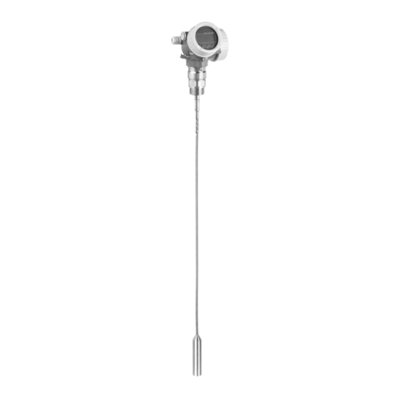
Levelflex FMP50
Guided wave radar
Level measurement in liquids
Application
• Rod or rope probe
• Process connection: 3/4" thread or adapter flange
• Process temperature: –20 to +80 °C (–4 to +176 °F)
• Process pressure: –1 to +6 bar (–14.5 to +87 psi)
• Maximum measuring range: Rod 4 m (13 ft); rope 12 m (39 ft)
• Accuracy: ±2 mm (±0.08 in)
• International explosion protection certificates; WHG; EN10204-3.1
• Linearity protocol (3-point, 5-point)
Your benefits
• Reliable measurement even for changing product and process conditions
• HistoROM data management for easy commissioning, maintenance and
diagnostics
• Highest reliability due to Multi-Echo Tracking
• Hardware and software developed according to IEC 61508 (up to SIL3)
• Seamless integration into control or asset management systems
• Intuitive user interface in national languages
• Bluetooth® wireless technology for commissioning, operation and maintenance via
free iOS / Android app SmartBlue
• Easy proof test for SIL and WHG
• Heartbeat Technology™
Solutions
Services
Advertisement
Table of Contents

Related Manuals for Endress+Hauser Levelflex FMP50


Summary of Contents for Endress+Hauser Levelflex FMP50
- Page 1 Solutions Services TI01000F/00/EN/25.22-00 71603691 2022-12-13 Technical Information Levelflex FMP50 Guided wave radar Level measurement in liquids Application • Rod or rope probe • Process connection: 3/4" thread or adapter flange • Process temperature: –20 to +80 °C (–4 to +176 °F) •...
-
Page 2: Table Of Contents
Levelflex FMP50 Table of contents Important document information ....4 Process pressure range ......49 Dielectric constant (DC) . - Page 3 Levelflex FMP50 Communication-specific accessories ....85 Service-specific accessories ..... . 86 System components .
-
Page 4: Important Document Information
Levelflex FMP50 Important document information Symbols Safety symbols DANGER This symbol alerts you to a dangerous situation. Failure to avoid this situation will result in serious or fatal injury. WARNING This symbol alerts you to a dangerous situation. Failure to avoid this situation can result in serious or fatal injury. -
Page 5: Function And System Design
Levelflex FMP50 Function and system design Measuring principle General principles The Levelflex is a "downward-looking" measuring system that functions according to the time-of- flight method (ToF). The distance from the reference point to the product surface is measured. High- frequency pulses are injected to a probe and led along the probe. The pulses are reflected by the product surface, received by the electronic evaluation unit and converted into level information. - Page 6 Levelflex FMP50 Dielectric constant The dielectric constant (DC) of the medium directly affects the degree of reflection of the high- frequency pulses. In the case of large DC values, such as with water or ammonia, there is strong pulse reflection while, in the case of low DC values, such as with hydrocarbons, pulse reflection is weak.
-
Page 7: Measuring System
• Measurement is unaffected by product properties • Hardware and software developed according to SIL IEC 61508 • Genuine, direct interface measurement Procurement • As the global market leader in level measurement, Endress+Hauser guarantees the security of your investment • Worldwide support and service Installation •... - Page 8 Levelflex FMP50 Rod probe • Maximum probe length 4 m (13 ft) • Material: 316L A0011388 3 Rope probe with centering rod Rope probe • Maximum probe length 12 m (40 ft) • Material: 316L Endress+Hauser...
-
Page 9: Input
Levelflex FMP50 Input Measured variable The measured variable is the distance between the reference point and the product surface. The level is calculated based on "E", the empty distance entered. Optionally, the level can be converted to other variables (volume, mass) by linearization (32 points). -
Page 10: Blocking Distance
Levelflex FMP50 Blocking distance The upper blocking distance (= UB) is the minimum distance from the reference point of the measurement (mounting flange) to the maximum level. 100% A0011279 4 Definition of blocking distance and safety distance Reference point of measurement... -
Page 11: Output
Levelflex FMP50 Output Output signal HART • Signal coding: FSK ±0.5 mA over current signal • Data transmission rate: 1 200 Bit/s • Galvanic isolation: Bluetooth® wireless technology • Device version: Order code 610 "Accessory mounted", option NF "Bluetooth" • Operation / configuration: Via the SmartBlue app •... -
Page 12: Signal On Alarm
Levelflex FMP50 • Scan rate: Corresponds to the measuring cycle • Signal source / device variables: • Level linearized • Distance • Terminal voltage • Electronic temperature • Relative echo amplitude • Diagnostic values, advanced diagnostic blocks • Only for active interface measurement •... -
Page 13: Protocol-Specific Data
Levelflex FMP50 Protocol-specific data HART Manufacturer ID 17 (0x11) Device type ID 0x1122 HART specification Device description files (DTM, DD) Information and files under: • www.endress.com • www.fieldcommgroup.org HART load min. 250 Ω HART device variables The measured values can be freely assigned to the device variables. - Page 14 Levelflex FMP50 PROFIBUS PA Manufacturer ID 17 (0x11) Ident number 0x1558 Profile version 3.02 GSD file Information and files under: • www.endress.com GSD file version • www.profibus.org Output values Analog Input: • Level linearized • Distance • Terminal voltage • Electronic temperature •...
- Page 15 Service with information about the state of the device Data Transfer Contains parameters for backing up the device No output values Transducer Block configuration in the display module and for writing the saved configuration to the device. Access to these parameters is reserved for Endress+Hauser Service. Endress+Hauser...
- Page 16 Levelflex FMP50 Function blocks Block Contents Number of Number of Execution Functionality permanent instantiatable time blocks blocks Resource Block The Resource Block contains all Enhanced the data that uniquely identify the device. It is an electronic version of a nameplate of the device.
- Page 17 Levelflex FMP50 Block Contents Number of Number of Execution Functionality permanent instantiatable time blocks blocks Integrator The Integrator Block integrates a 25 ms Standard Block variable as a function of the time or accumulates the counts from a Pulse Input Block. The Block can...
-
Page 18: Power Supply
Levelflex FMP50 Power supply Terminal assignment Terminal assignment, 2-wire: 4 to 20 mA HART A0036498 5 Terminal assignment, 2-wire: 4 to 20 mA HART Without integrated overvoltage protection With integrated overvoltage protection Connection 4 to 20 mA, HART passive: terminals 1 and 2, without integrated overvoltage protection... - Page 19 Levelflex FMP50 Block diagram, 2-wire: 4 to 20 mA HART, switch output A0036501 8 Block diagram, 2-wire: 4 to 20 mA HART, switch output Active barrier for power supply (e.g. RN221N); observe terminal voltage Resistor for HART communication (≥ 250 Ω); observe maximum load Connection for Commubox FXA195 or FieldXpert SFX350/SFX370 (via VIATOR Bluetooth modem) Analog display unit;...
- Page 20 Levelflex FMP50 Block diagram, 2-wire: 4 to 20 mAHART, 4 to 20 mA A0036502 10 Block diagram, 2-wire: 4 to 20 mAHART, 4 to 20 mA Active barrier for power supply (e.g. RN221N), current output 1; observe terminal voltage Resistor for HART communication (≥...
- Page 21 Levelflex FMP50 Terminal assignment, 4-wire: 4 to 20 mA HART (90 to 253 V A0036519 13 Terminal assignment, 4-wire: 4 to 20 mAHART (90 to 253 V Connection 4 to 20 mA HART (active): terminals 3 and 4 Connection, supply voltage: terminals 1 and 2...
- Page 22 Levelflex FMP50 Terminal assignment PROFIBUS PA / FOUNDATION Fieldbus A0036500 15 Terminal assignment PROFIBUS PA / FOUNDATION Fieldbus Without integrated overvoltage protection With integrated overvoltage protection Connection, PROFIBUS PA / FOUNDATION Fieldbus: terminals 1 and 2, without integrated overvoltage...
-
Page 23: Device Plug
Signal + Not assigned Signal - Ground A0011176 20 Pin assignment of 7/8" plug Signal - Signal + Not assigned Shielding An external power supply is necessary. Supply voltage Various power supply units can be ordered from Endress+Hauser. Endress+Hauser... - Page 24 Levelflex FMP50 2-wire, 4-20mA HART, passive 2-wire; 4-20mA HART "Approval" Terminal voltage U at device Maximum load R, depending on the supply voltage U of the power supply unit 3) 4) • Non-hazardous 11.5 to 35 V R [ ] •...
- Page 25 Levelflex FMP50 2-wire; 4-20mA HART, 4-20mA "Approval" Terminal voltage U at device Maximum load R, depending on the supply voltage U of the power supply unit Channel 1: 3) 4) 5) 13.5 to 30 V R [ ] Ω 13.5 24.5...
-
Page 26: Power Consumption
Levelflex FMP50 4-wire, 4-20mA HART, active "Power supply; output" Terminal voltage U Maximum load R K: 4-wire 90-253VAC; 4-20mA HART 90 to 253 V (50 to 60 Hz), overvoltage 500 Ω category II L: 4-wire 10.4-48VDC; 4-20mA HART 10.4 to 48 V... -
Page 27: Power Supply Failure
Levelflex FMP50 FOUNDATION Fieldbus Device basic current 15 mA Failure current FDE (Fault 0 mA Disconnection Electronic) FISCO 17.5 V 550 mA 5.5 W 5 nF 10 μH Power supply failure • Configuration is retained in the HistoROM (EEPROM). • Error messages (incl. value of operated hours counter) are stored. -
Page 28: Overvoltage Protection
< 1.5 pF Nominal arrest impulse voltage (8/20 μs) 10 kA External overvoltage protection module HAW562 or HAW569 from Endress+Hauser are suited as external overvoltage protection. For detailed information please refer to the following documents: • HAW562: TI01012K • HAW569: TI01013K... -
Page 29: Performance Characteristics
Levelflex FMP50 Performance characteristics Reference operating • Temperature = +24 °C (+75 °F) ±5 °C (±9 °F) conditions • Pressure = 960 mbar abs. (14 psia) ±100 mbar (±1.45 psi) • Humidity = 60 % ±15 % • Reflection factor ≥ 0.8 (metal plate for rod and rope probe with min. 1 m (40 in) diameter) •... -
Page 30: Resolution
Levelflex FMP50 80 (3.15) 60 (2.36) DC = 80 40 (1.57) 20 (0.79) -20 (-0.79) -40 (-1.57) -60 (-2.36) -80 (-3.15) A0021482 22 Measured error at the probe end for rope probes Distance from the probe end [mm(in)] Measured error: Sum of non-linearity, non-repeatability and hysteresis If the DC value is less than 7 in the case of rope probes, measurement is not possible in the area of the tensioning weight (0 to 250 mm from the probe end), (lower blocking distance). -
Page 31: Response Time
Levelflex FMP50 Response time The response time can be configured. The following step response times (in accordance with DIN EN IEC 61298-2 / DIN EN IEC 60770-1) are when damping is switched off: Level measurement Probe length Sampling rate Response time <... -
Page 32: Mounting
Levelflex FMP50 Mounting Mounting requirements Suitable mounting position A0012606 24 Installation conditions for Levelflex Spacing requirements when mounting • Distance (A) between the vessel wall and rod and rope probes: • For smooth metallic walls: > 50 mm (2 in) •... - Page 33 Levelflex FMP50 Additional conditions • When mounting outdoors, a weather protection cover (1) can be used to protect the device against extreme weather conditions. • In metallic vessels, preferably do not mount the probe in the center of the vessel (2), as this would lead to increased interference echoes.
- Page 34 Levelflex FMP50 Mounting under confined conditions Mounting with remote probe The device version with a remote probe is suitable for applications with restricted mounting space. In this case, the electronics housing is mounted at a separate position from the probe.
- Page 35 Levelflex FMP50 Notes on the mechanical load of the probe Tensile loading capacity of rope probes FMP50 Rope 4mm (1/6") 316 2 kN Lateral loading capacity (flexural strength) of rod probes FMP50 Rod 8mm (1/3") 316L 10 Nm Lateral load (bending moment) from flow conditions...
- Page 36 Levelflex FMP50 Information concerning the process connection Probes are mounted on the process connection with threaded connections or flanges. If there is the danger with this installation that the probe end moves so much that it occasionally touches the vessel floor or cone, the probe may need to be shortened at the lower end and fixed in place.
- Page 37 Levelflex FMP50 Mounting in nozzles ≥ DN300 If installation in nozzles ≥ 300 mm (12 in) is unavoidable, installation must be carried out in accordance with the following diagram in order to avoid interference signals in the near range. A0014199 Lower edge of the nozzle Approximately flush with the lower edge of the nozzle (±50 mm)
- Page 38 Levelflex FMP50 Securing the probe Securing rope probes A0012609 Rope sag: ≥ 10 mm/(1 m probe length) [0.12 in/(1 ft probe length)] Reliably grounded end of probe Reliably insulated end of probe Fastener in female thread of probe end weight Insulated fastening kit •...
- Page 39 Levelflex FMP50 Securing rod probes • For WHG approval: A support is required for probe lengths ≥ 3 m (10 ft). • In general, rod probes must be secured in the event of horizontal flow (e.g. from an agitator) or strong vibrations.
- Page 40 Levelflex FMP50 Special installation situations Bypasses and stilling wells The use of centering disks/stars/weights (available as accessories) is recommended in bypass and stilling well applications. As the measuring signal penetrates many plastics, installation in plastic bypasses or stilling wells can produce incorrect results. For this reason use a metal bypass or stilling well.
- Page 41 Levelflex FMP50 Underground tanks A0014142 In the case of nozzles with large diameters, use FMP51 with a coax probe to avoid reflections at the nozzle wall. Endress+Hauser...
- Page 42 Levelflex FMP50 Mounting at an angle A0014145 • For mechanical reasons, the probe should be installed as vertically as possible. • If the probe is installed at an angle, the length of the probe must be reduced depending on the angle of installation.
- Page 43 Levelflex FMP50 Non-metal vessels A0012527 Non-metal vessel Metal sheet or metal flange To ensure good measurement results when mounting on non-metal vessels, at the process connection mount a metal sheet with a diameter of at least 200 mm (8 in) at a right angle to the probe.
- Page 44 Levelflex FMP50 Plastic and glass vessels: Mounting the probe on the outside wall In the case of plastic and glass vessels, the probe can also be mounted on the outside wall under certain conditions. A0014150 Plastic or glass vessel Metal plate with screw-in sleeve...
- Page 45 Levelflex FMP50 Vessel with thermal insulation If process temperatures are high, the device must be included in normal vessel insulation (1) in order to prevent the electronics heating up as a result of thermal radiation or convection. The insulation may not go beyond the points labeled "MAX" in the drawings.
-
Page 46: Environment
Levelflex FMP50 Environment Ambient temperature Measuring device –20 to +80 °C (–4 to +176 °F) Local display –20 to +70 °C (–4 to +158 °F), the readability of the local display may be impaired at temperatures outside the temperature range. - Page 47 Levelflex FMP50 In the event of temperature (T ) at the process connection, the permitted ambient temperature (T is reduced as indicated in the following diagram (temperature derating): Temperature derating for FMP50 with threaded connection G¾ or NPT¾ [°C] ([°F])T a +80(+176) 4...20 mA HART...
-
Page 48: Storage Temperature
Levelflex FMP50 Storage temperature • Permitted storage temperature: –40 to +80 °C (–40 to +176 °F) • Use original packaging. Climate class DIN EN 60068-2-38 (test Z/AD) Altitude according to • Generally up to 2 000 m (6 600 ft) above MSL. -
Page 49: Process
Levelflex FMP50 Process Process temperature range The maximum temperature permitted at the process connection is determined by the O-ring version ordered: Device O-ring material Process temperature Approval FMP50 FKM (Viton GLT) –20 to +80 °C (–4 to 176 °F) Process pressure range... -
Page 50: Mechanical Construction
Levelflex FMP50 Mechanical construction Dimensions Dimensions of the electronics housing 99 (3.9)* 78 (3.07) 90 (3.54) A0011346 27 GT19 housing (plastic PBT). Unit of measurement mm (in) *For devices with integrated overvoltage protection. 98 (3.86)* 78 (3.07) 90 (3.54) A0020751 ... - Page 51 Levelflex FMP50 Mounting bracket dimensions ø42...60 (1.65...2.36) 127...140 122 (4.8) (5...5.51) 161 (6.34) 162...175 (6.38...6.89) A0014793 29 Mounting bracket for electronics housing. Unit of measurement mm (in) Wall mounting Post mounting With "remote sensor" device versions (see feature 060 in the product structure), the mounting bracket is included in the scope of delivery.
- Page 52 Levelflex FMP50 FMP50: Dimensions of process connection/probe 36 mm G¾ NPT¾ 7 mm 7 mm ø4 (0.16) ø8 (0.31) ø22 (0.87) A0012644 31 FMP50: Process connection / probe. Unit of measurement mm (in) Thread ISO228 G3/4 or ANSI MNPT3/4 (feature 100) Rod probe 8mm or 1/3"...
-
Page 53: Probe Length Tolerances
Levelflex FMP50 Probe length tolerances Rod probes Permitted tolerance depending on the probe length: • < 1 m (3.3 ft) = –5 mm (–0.2 in) • 1 to 3 m (3.3 to 9.8 ft) = –10 mm (–0.39 in) • 3 to 6 m (9.8 to 20 ft) = –20 mm (–0.79 in) •... -
Page 54: Weight
Levelflex FMP50 Weight Housing Part Weight GT19 housing - plastic Approx. 1.2 kg GT20 housing - aluminum Approx. 1.9 kg FMP50 Part Weight Part Weight Sensor Approx. 0.25 kg Rope probe 4 mm Approx. 0.1 kg/m probe length Rod probe 8 mm Approx. -
Page 55: Materials: Gt20 Housing (Die-Cast Aluminum, Powder- Coated)
Levelflex FMP50 Materials: GT20 housing (die-cast aluminum, powder- coated) A0036037 33 Material; GT20 housing Housing RAL 5012 (blue); AlSi10Mg (<0.1% Cu), coating; polyester 2.1 Electronics compartment cover RAL 7035 (gray); AlSi10Mg (<0.1% Cu), seals; NBR, window; glass, thread coating; graphite-based lubricant varnish 2.2 Connection compartment cover RAL 7035 (gray);... -
Page 56: Materials: Process Connection
Levelflex FMP50 Materials: Process Levelflex FMP50 connection Threaded connection No. Material G¾, NPT¾ PPS-GF40 316L (1.4404) PPS-GF40 A0013834 Endress+Hauser... -
Page 57: Materials: Probe
Levelflex FMP50 Materials: Probe Levelflex FMP50 Feature 060 "Probe" Material • AA: rod 8mm • LA: rope 4mm • AB: rod 1/3" • LB: rope 1/6" 316L (1.4404) 316 (1.4401) Setscrew: A4-70 Bracing screw: A2-70 A0036583 A0036584 Endress+Hauser... -
Page 58: Materials: Mounting Bracket
Levelflex FMP50 Materials: Mounting bracket A0015143 Mounting bracket for "remote sensor" version Component Material Holder 316L (1.4404) Round bracket 316Ti (1.4571) Screws/nuts A4-70 Distance sleeves 316Ti (1.4571) or 316L (1.4404) Half-shells 316L (1.4404) Endress+Hauser... -
Page 59: Materials: Adapter And Cable For Remote Sensor
Levelflex FMP50 Materials: Adapter and cable for remote sensor A0021722 Adapter and cable for "remote sensor" version Component Material Cable FRNC Sensor adapter 304 (1.4301) Terminal 316L (1.4404) Screw A4-70 Band 316 (1.4401) Crimp sleeve Aluminum Nameplate 304 (1.4301) Endress+Hauser... -
Page 60: Materials: Weather Protection Cover
Levelflex FMP50 Materials: weather protection cover A0015473 34 Material; weather protection cover Protection cap; 316L (1.4404) Molded rubber part (4x); EPDM Clamping screw; 316L (1.4404) + carbon fiber Bracket; 316L (1.4404) Ground terminal; A4, 316L (1.4404) Fillister-head screw; A4-70 + washer; A4... - Page 61 Levelflex FMP50 Integrated data memory (HistoROM) • Adoption of data configuration when electronics modules are replaced • Up to 100 event messages recorded in the device • Data logging with up to 1000 logged values • A reference signal curve is saved during commissioning for later use as a reference during...
-
Page 62: Local Operation
Levelflex FMP50 Local operation Operation Pushbuttons Touch Control with Order code for Option C "SD02" Option E "SD03" "Display; Operation" A0036312 A0036313 Display 4-line display 4-line display elements white background lighting; switches to red in event of device error Format for displaying measured variables and status variables can be individually configured Permitted ambient temperature for the display: –20 to +70 °C (–4 to +158 °F) -
Page 63: Operation Via Bluetooth® Wireless Technology
Levelflex FMP50 Operation via Bluetooth® Requirements wireless technology A0036790 36 Device with Bluetooth module Electronics housing of the device Bluetooth module This operation option is only available for devices with Bluetooth module. There are the following options: • The device has been ordered with a Bluetooth module: Feature 610 "Accessory Mounted", option NF "Bluetooth"... -
Page 64: Remote Operation
Levelflex FMP50 Remote operation Via HART protocol A0044334 38 Options for remote operation via HART protocol PLC (programmable logic controller) Transmitter power supply unit, e.g., RN42 Connection for Commubox FXA195 and AMS Trex device communicator AMS Trex device communicator Computer with operating tool (e.g., DeviceCare/FieldCare, AMS Device View, SIMATIC PDM) - Page 65 Levelflex FMP50 Via FOUNDATION Fieldbus FF-HSE FF-H1 FF-H1 A0017188 39 FOUNDATION Fieldbus system architecture with associated components FFblue Bluetooth modem Field Xpert SFX350/SFX370 DeviceCare/FieldCare NI-FF interface card Industrial network FF-HSE High Speed Ethernet FF-H1 FOUNDATION Fieldbus-H1 Linking Device FF-HSE/FF-H1...
- Page 66 Levelflex FMP50 Via service interface (CDI) A0039148 Computer with FieldCare/DeviceCare operating tool Commubox FXA291 Service interface (CDI) of the measuring device (= Endress+Hauser Common Data Interface) Endress+Hauser...
-
Page 67: Integration Into The Tank Gauging System
Levelflex FMP50 Integration into the Tank The Endress+Hauser Tank Side Monitor NRF81 has integrated communication functions for sites with multiple tanks, wherein each tank can have one or more sensors, e.g. radar, spot or average Gauging System temperature sensors, capacitance probes for water detection and/or pressure sensors. As the Tank Side Monitor supports multiple protocols, it can work with virtually all industry standard tank gauging protocols. - Page 68 Levelflex FMP50 SupplyCare inventory SupplyCare is a web-based operating program for coordinating the flow of material and information along the supply chain. SupplyCare provides a comprehensive overview of the levels of management software geographically distributed tanks and silos, for instance, providing complete transparency over the current inventory situation, regardless of time and location.
- Page 69 Levelflex FMP50 A0034288 41 Example of inventory management platform with SupplyCare Enterprise SCE30B SupplyCare Enterprise (via Web browser) SupplyCare Enterprise installation SupplyCare Enterprise on mobile devices (via Web browser) Ethernet/WLAN/UMTS Fieldgate FXA42 Power supply 24 V DC Modbus TCP via Ethernet as server/client...
- Page 70 Levelflex FMP50 Cloud-based application: SupplyCare Hosting SupplyCare Hosting is offered as a hosting service (software as a service). Here, the software is installed within the Endress+Hauser IT infrastructure and made available to the user in the Endress +Hauser portal. A0034289 ...
-
Page 71: Certificates And Approvals
The separate "Safety Instructions" documentation (XA) containing all the relevant explosion protection data is available from your Endress+Hauser sales organization. Dual seal according to The devices have been designed according to ANSI/ISA 12.27.01 as dual seal devices, allowing the user to waive the use and save the cost of installing external secondary process seals in the conduit ANSI/ISA 12.27.01... -
Page 72: Radio Approval
Levelflex FMP50 Radio approval Satisfies "Part 15" of the FCC rules for an unintentional radiator. All probes meet the requirements for a Class A digital device. In addition, coax probes and all probes in metal vessels meet the requirements for a Class B digital device. -
Page 73: Test, Certificate
Levelflex FMP50 Test, certificate Feature 580 "Test, certificate" Designation Approval 3.1 Material documentation, wetted metal parts, EN10204-3.1 FMP50 inspection certificate Test reports, declarations and inspection certificates are available in electronic format in the W@M Device Viewer: Enter the serial number from the nameplate (www.endress.com/deviceviewer) This concerns the options for the following order codes: •... -
Page 74: Other Standards And Guidelines
Levelflex FMP50 Other standards and • EN 60529 Degrees of protection provided by enclosures (IP code) guidelines • EN 61010-1 Safety requirements for electrical equipment for measurement, control and laboratory use • IEC/EN 61326 "Emission in accordance with Class A requirements". Electromagnetic compatibility (EMC requirements). -
Page 75: Ordering Information
• Depending on the device: Direct input of measuring point-specific information such as measuring range or operating language • Automatic verification of exclusion criteria • Automatic creation of the order code and its breakdown in PDF or Excel output format • Ability to order directly in the Endress+Hauser Online Shop Endress+Hauser... -
Page 76: 3-Point Linearity Protocol
Levelflex FMP50 3-point linearity protocol The following points must be considered if option F3 (3-point linearity protocol) was selected in feature 550 ("Calibration"). The 3 points of the linearity protocol are defined as follows, depending on the selected probe: A0021843... -
Page 77: 5-Point Linearity Protocol
Levelflex FMP50 5-point linearity protocol The following points must be considered if option F4 (5-point linearity protocol) was selected in feature 550 ("Calibration"). The 5 points of the linearity protocol are evenly distributed over the measuring range (0% - 100%). -
Page 78: Application Packages
Levelflex FMP50 Customized If the option IJ: "Customized parameterization HART", IK "Customized parameterization PA" or IL "Customized parameterization FF" has been selected in feature 570 "Service", presettings that differ parameterization from the default settings can be selected for the following parameters:... -
Page 79: Heartbeat Verification
Levelflex FMP50 Heartbeat Verification Availability Available for the following versions of feature 540 "Application package": • EH Heartbeat Verification + Monitoring • EJ Heartbeat Verification Device functionality checked on demand • Verification of the correct functioning of the measuring device within specifications. -
Page 80: Accessories
Levelflex FMP50 "Foam detection" wizard • The Heartbeat Monitoring module contains the Foam detection wizard. • This wizard is used to configure automatic foam detection, which detects foam on the product surface on the basis of the reduced signal amplitude. Foam detection can be linked to a switch output in order to control a sprinkler system, for example, which dissolves the foam. - Page 81 Levelflex FMP50 202 (7.95) 299 (11.8) A0015472 44 Dimensions. Unit of measurement mm (in) Material 316L Order number for accessories: 71162242 Mounting bracket for electronics housing Accessories Description Mounting bracket for electronics housing ø42...60 (1.65...2.36) 122 (4.8) 127...140 (5...5.51) 161 (6.34)
- Page 82 Levelflex FMP50 Mounting kit, insulated Accessories Description Mounting kit, insulated suitable for FMP50 A0013586 46 Scope of delivery of mounting kit: Insulation sleeve Eye bolt To secure rope probes so that they are reliably insulated. Maximum process temperature: 150 °C (300 °F) For rope probes 4 mm (¹⁄₆...
- Page 83 Levelflex FMP50 Centering star Accessories Description Centering star PFA • 16.4 mm (0.65 in) • 37 mm (1.46 in) suitable for FMP50 A0014577 For probe 8 mm (0.3 in) For probes 12 mm (0.47 in) and 16 mm (0.63 in) The centering star is suitable for probes with a rod diameter of 8 mm (0.3 in),...
- Page 84 Levelflex FMP50 Technical data • Material: • Plastic PBT • 316L/1.4404 • Aluminum • Degree of protection: IP68 / NEMA 6P and IP66 / NEMA 4x • Suitable for display modules: • SD02 (push buttons) • SD03 (touch control) • Connecting cable: •...
-
Page 85: Communication-Specific Accessories
Levelflex FMP50 If retrofitting: • Order number for 1-channel devices (OVP10): 71128617 • Order number for 2-channel devices (OVP20): 71128619 • The use of the OVP module may be restricted depending on the transmitter approval. A device may only be retrofitted with the OVP module if the option NA (overvoltage protection) is listed under Optional specifications in the Safety Instructions (XA) associated with the device. -
Page 86: Service-Specific Accessories
Levelflex FMP50 Commubox FXA291 Connects Endress+Hauser field devices with a CDI interface (= Endress+Hauser Common Data Interface) and the USB port of a computer or laptop Order number: 51516983 For details, see "Technical Information" TI00405C HART Loop Converter HMX50 Is used to evaluate and convert dynamic HART process variables to analog current signals or limit... -
Page 87: System Components
Technical Information TI00081R and Brief Operating Instructions KA00110R Supplementary documentation The following document types are available in the Downloads section of the Endress+Hauser website (www.endress.com/downloads): For an overview of the scope of the associated Technical Documentation, refer to the following: •... - Page 88 *71603691* 71603691 www.addresses.endress.com...