Table of Contents
Advertisement
Quick Links
Advertisement
Table of Contents

Related Manuals for Kenwood ProTalk TK-3710


Summary of Contents for Kenwood ProTalk TK-3710
- Page 1 TK-3710 USER MANUAL B5A-3235-00_EN...
-
Page 2: Table Of Contents
CONTENTS PREPARATION ....................4 INSTALLING/ REMOVING THE BATTERY PACK .......... 4 INSTALLING THE ANTENNA ................. 5 INSTALLING THE BELT CLIP ................ 5 INSTALLING THE CAP OVER THE SPEAKER/ MICROPHONE JACKS ..6 INSTALLING THE SPEAKER/ MICROPHONE OR HEADSET ...... 6 ORIENTATION .................... - Page 3 ACCESSIBLE FUNCTIONS................17 FUNCTION MODE ..................17 MENU MODE ....................17 Menu Access ....................17 FUNCTIONS LIST ..................19 FUNCTIONS OVERVIEW ................21 FUNCTION DESCRIPTIONS ................43 TRANSCEIVER PASSWORD ................ 43 SCAN......................44 TEMPORARY CHANNEL LOCKOUT ............44 PRIORITY SCAN ..................44 SCAN REVERT ....................
-
Page 4: Preparation
PREPARATION INSTALLING/ REMOVING THE BATTERY PACK The battery pack is not charged at the factory; charge it before use. Align the battery pack with the back of the transceiver, then press the battery pack and transceiver firmly together until the release latch on the base of the transceiver locks. -
Page 5: Installing The Antenna
INSTALLING THE ANTENNA Screw the antenna into the connector on the top of the Antenna transceiver by holding the antenna at its base and turning it clockwise until secure. INSTALLING THE BELT CLIP If necessary, attach the belt clip using the two Belt clip supplied M3 x 8 mm binding screws. -
Page 6: Installing The Cap Over The Speaker/ Microphone Jacks
INSTALLING THE CAP OVER THE SPEAKER/ MICROPHONE JACKS Note: ◆ For the speaker/ microphone jack, waterproof performance is guaranteed by securing the supplied cap. Waterproof performance will not be guaranteed by connecting an optional speaker/ microphone, etc. ◆ Use the Phillips #1 screwdriver. If you are not using an optional speaker/ microphone or headset, install the cap over the speaker/ microphone jacks. -
Page 7: Orientation
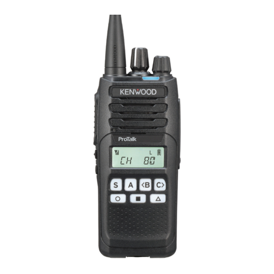
ORIENTATION Buttons and Controls Antenna Speaker Microphone Display Battery pack a Selector Rotate to change the operating channel. b Status indicator Refer to the “LED INDICATOR STATUS” {p. 13}. c Power switch/ Volume control Turn clockwise to switch ON the transceiver. To switch OFF the transceiver, turn counterclockwise until a click sounds. - Page 8 e [ ], [ ], and [ ] buttons [ ] button (Scan Delete/Add) Press this button to remove an undesired channel from the scanning sequence {p. 16}. [ ] button (Battery Status) Press this button, the Battery Status function operates. {p. 13}. [ ...
-
Page 9: Display
Display Indicator Description Displays the signal strength. The Monitor * or Squelch Off function is activated. Appears when Calling. * Appears while Scanning. Indicates Priority Channel. * The channel is using low transmit power. Appears when the transceiver is operating in Duplex mode. -
Page 10: Basic Operation
BASIC OPERATION POWER ON Turn the Power switch/ Volume control clockwise to switch the transceiver power ON. • Beep A (1 beep) will sounds and the display momentarily lights up. ADJUST THE VOLUME Rotate the Power switch/ Volume control to adjust the volume. •... -
Page 11: Receive Voice
RECEIVE VOICE The LED lights in green. When the other party transmits it, you hear the voice of the other party. POWER OFF After use, turn off the power. To switch the transceiver power OFF, turn the Power switch/ Volume control fully counterclockwise, until a click sounds. -
Page 12: Transmit Power
TRANSMIT POWER Press the [ A ] button to change the transmit power of all transceiver channels to low power (you cannot change low transmit power channels to high power). Press the [ A ] button again to return all channels to their default transmit power setting. •... -
Page 13: Battery Status
BATTERY STATUS Allows you to check the battery power status. Press the [ ] button, the Battery Status function operates. Battery status is represented by the number of times the LED indicator flashes red. Four flashes represents full power, three represents medium power, two represents low power, and one represents very low power. -
Page 14: Operator Selectable Tone (Ost)
OPERATOR SELECTABLE TONE (OST) You may have programmed CTCSS or DCS signaling on your transceiver channels. A CTCSS tone/ DCS code is a sub-audible tone/code which allows you to ignore (not hear) calls from other parties who are using the same channel. When a channel is set up with a CTCSS tone or DCS code, squelch will only open when a call containing a matching tone or code is received. -
Page 15: Available Ctcss Frequencies (Hz)
Note: ◆ The OST function will not work on channels 5 and 35 (emergency channels). ◆ If the OST function is used on channels 22 and 23, only the decoding values will be set. Encoding values will not be set, as transmission is inhibited on these channels (data channels). -
Page 16: Scan
SCAN Scan monitors for signals on the transceiver channels. While scanning, the transceiver checks for a signal on each channel and only stops if a matching signal is present. To start/stop scanning, press the [ S ] button. • “SCAN” appears and the “ ”... -
Page 17: Accessible Functions
ACCESSIBLE FUNCTIONS FUNCTION MODE Your transceiver operations vary according to the functions that your dealer has programmed to the transceiver buttons. Refer to “FUNCTIONS LIST” {p. for the available programmable functions. MENU MODE Many functions on this transceiver are selected or configured through the Menu instead of physical controls. - Page 18 Press the [ S ] button to view the function list for the selected category. Press [ <B ] and [ C> ] to select a function item. Press the [ A ] button to return to the category list. •...
-
Page 19: Functions List
FUNCTIONS LIST PF Button : Functions that can be programmed to the transceiver buttons Menu : Functions that can be accessed using the transceiver Menu ✔: Available N/A: Not Available Function Menu Display PF Button Menu None – ✔ Autodial AUTODIAL ✔... - Page 20 Function Menu Display PF Button Menu Low Transmit Power LOW PWR ✔ ✔ Maintenance MAINT ✔ ✔ Medium Transmit Power MED PWR ✔ ✔ Menu – ✔ Medium Transmit Power MED PWR ✔ ✔ Microphone Sense MIC SENS ✔ Monitor MONITOR ✔...
-
Page 21: Functions Overview
FUNCTIONS OVERVIEW Following is a brief overview of the functions available on the transceiver accessible using the Menu and/or programmable to the transceiver buttons. • For details on functions that are not included in “FUNCTIONS OVERVIEW” and “FUNCTION DESCRIPTIONS” {p. 43}, please consult your dealer. None No function has been programmed. - Page 22 Battery Status Allows you to check the battery power status. PF Button: Press the programmed button, the Battery Status function operates. Menu Mode: Select “BAT STAT” and press the [ S ] button, the Battery Status function operates. Battery status is represented by the number of times the LED indicator flashes red.
- Page 23 Button Lock Locking the transceiver button operation. This function prevents the incorrect operation of the transceiver by physical contact while carrying the transceiver, such as around the waist. PF Button: Press the programmed button to lock the transceiver buttons. • Beep A (1 beep) sounds.
- Page 24 Call 1 ~ 6 Allows you to send assigned signaling from Call 1 to Call 6. PF Button: Press the programmed button to send a message or initiate a call. Calling Alert Allows you to send a calling alert to the other party. Calling alert tones help identify yourself to party members and inform them that you are calling.
- Page 25 Channel Entry In Channel Entry Mode, channel can be selected by the same operation as List selection. PF Button: Press the programmed button to enter Channel Entry Mode. Press the [ <B ] and [ C> ] buttons to select your desired channel. Press the [ S ] button to confirm the entry.
- Page 26 To enter 3-digit channel number (example: Channel 123): 1 Press the programmed button to enter Channel Entry Mode. Press the [ <B ] and [ C> ] buttons to select “1” Press the [ S ] button. Press the [ <B ] and [ C> ] buttons to select “2”. Press the [ S ] button.
- Page 27 Direct Channel 1 ~ 5 Allows you to go directly to Direct Channel 1 ~ 5. PF Button: Press the programmed button to jump to a frequently used zone and channel. • Beep A (1 beep) sounds. Press this button again to return to the formerly selected channel. •...
- Page 28 Display Format Allows you to switch the display between the zone-channel number and the channel name. Zone-channel number Channel name PF Button: Press the programmed button to switch the display between the zone-channel number and the channel name. Menu Mode: Select “DISP FMT”...
- Page 29 External Microphone Sense Allow you to set the microphone sensitivity of the external microphone. Menu Mode: Select “EX MIC S” and press the [ S ] button. Press the [ <B ] and [ C> ] buttons to select the microphone sensitivity. •...
- Page 30 Fixed Volume Allows you to change the volume level of the tone. PF Button: Press the programmed button to change Low, High, or Off (Tone Off). Menu Mode: 1 Select “FIXED V” and press the [ S ] button. 2 Press the [ <B ] and [ C> ] buttons to select Low, High, or Off (Tone Off). Press the [ S ] button to confirm and exit mode.
- Page 31 Function Allows you to access the 2nd function programmed to a button. Programmable buttons can be assigned Main function and 2nd function. PF Button: Press the programmed button to enter 2nd function input wait state. • Beep A (1 beep) sounds. •...
- Page 32 Home Channel Allows you to jump to home channel (programmed by your dealer). If activated by your dealer, you can set your own Home Channel by selecting your desired channel using Home Channel Select. PF Button: Press the programmed button to jump to home channel. •...
- Page 33 Low Transmit Power Turns Low Transmit Power On or Off. When using a channel programmed with medium or high power, this allows you to change the output power to low. PF Button: Press the programmed button to change the output power to Low. •...
- Page 34 Maintenance Allows you to display the signal strength on the LCD when constructing the system or during maintenance. PF Button: Press the programmed button to enter Maintenance Display Mode. Menu Mode: Select “MAINT” and press the [ S ] button to enter Maintenance Display Mode.
- Page 35 Microphone Sense Allows you to change the internal microphone sensitivity. Menu Mode: Select “MIC SENS” and press the [ S ] button. Press the [ <B ] and [ C> ] buttons to select the microphone sensitivity. • You can select from +6 dB (High sensitivity) to -20 dB (Low sensitivity) by 2 step.
- Page 36 Monitor Momentary PF Button: Press and hold the programmed button to momentarily turn the transceiver signaling off. Releasing this button turns the transceiver signaling back on. While signaling is off, you can listen to all calls that are received on the channel. Operator Selectable Tone Switches the preset CTCSS/DCS Decode/Encode pair to an OST (Operator Selectable Tone) pair.
- Page 37 Priority-channel Select A Priority channel must be programmed in order for Priority Scan to function. When using a single Priority channel, the transceiver will automatically change to the Priority channel when a call is received on it, even if a call is being received on a normal channel.
- Page 38 Save Log Data This function saves the operation and communication logs of this transceiver. • This function is for field support use such for your dealer. Scan Allows you starting or stopping scan. PF Button: Press the programmed button to start scanning. To stop scanning, press this button.
- Page 39 Speaker Attenuation Temporarily reduce the volume level of the speaker of the transceiver and speaker/ microphone. PF Button: Press the programmed button to change the Speaker Attenuation On or Off. Squelch Level Allows you to adjust the transceiver squelch level. PF Button: Press the programmed button to enter Squelch Level Adjustment Mode.
- Page 40 Squelch Off Momentary PF Button: Press and hold the programmed button to momentarily turn the transceiver squelch off. Releasing this button turns the transceiver squelch back on. While squelch is off, you can better hear weak signals on the channel. Transceiver Password Allows you to enter Transceiver Password Input Mode.
- Page 41 VOX Function VOX (VOX/ Semi-VOX) operation allows you to transmit hands-free. This feature can be activated or deactivated by your dealer. To operate VOX, you must use an optional headset. PF Button: Press and hold the programmed button to switch the VOX operation On. •...
- Page 42 Zone Up/ Zone Down Press the programmed button to increase/ decrease the zone number. Zone Up (Continuous)/ Zone Down (Continuous) Hold down the programmed button to continuously increase/ decrease the zone number.
-
Page 43: Function Descriptions
FUNCTION DESCRIPTIONS For details on functions that are not included in “FUNCTIONS OVERVIEW” {p. 21} and “FUNCTION DESCRIPTIONS”, please consult your dealer. TRANSCEIVER PASSWORD If the transceiver is password protected, “PASSWORD” will appear on the display when the power is turned on. To unlock the transceiver, enter the correct password. -
Page 44: Scan
SCAN Scan is useful for monitoring signals on the transceiver channels. While scanning, the transceiver checks for a signal on each channel and only stops on a channel if a signal is present. To begin scanning, press the button programmed as [Scan]. •... -
Page 45: Scan Revert
SCAN REVERT The Scan Revert channel is the channel selected when you press the PTT switch to transmit during scan. Your dealer can program one of the following Scan Revert channels: Selected: The last channel selected is assigned as the new revert channel. •... -
Page 46: Voice Operated Transmission (Vox)
VOICE OPERATED TRANSMISSION (VOX) VOX (VOX/ Semi-VOX) operation allows you to transmit hands-free. This feature can be activated or deactivated by your dealer. To operate VOX, you must use an optional headset. VOX Type VOX: When the voice level to the microphone is higher than the reference level (VOX Gain Level), the transceiver automatically starts transmission. -
Page 47: Semi-Vox Operation
Semi-VOX Operation Connect a headset to the transceiver. • The VOX function does not activate when a headset is not connected to the accessory terminal of the transceiver. Press the button programmed as [VOX Function]. Alternatively, you can press the button programmed as [Menu] to enter •... -
Page 48: Background Operations
BACKGROUND OPERATIONS TIME-OUT TIMER (TOT) The Time-out Timer is used to prevent any caller from using a channel for an extended period of time. If you continuously transmit for a period of time that exceeds the programmed time, the transceiver will stop transmitting and an alert tone will sound. To stop the tone, release the PTT switch. -
Page 49: Voice Announcement
VOICE ANNOUNCEMENT An audio voice will be announced as below by dealer setting. • When changing the zone and/or channel, the new zone and channel number are announced. • When changing the function setting, the new setting is announced. - VOX Function - Home Channel - Button Lock - Low Transmit Power... -
Page 50: Specifications
SPECIFICATIONS GENERAL 476.4250 ~ 477.4125 MHz Frequency Range Narrow 12.5 kHz Channel Spacing Wide 25 kHz 7.5 V DC ± 20 % Operating Voltage –30°C ~ + 60°C Operating Temperature Range ± 0.5 ppm Frequency Stability Antenna Impedance 50 Ω Battery Life with KNB-84L (Calculated using 5% transmit time, 5% 11 hours... -
Page 51: Uhf Cb Channels & Frequencies
UHF CB CHANNELS & FREQUENCIES CB Channel Frequency Remark Number (MHz) 476.425000 Duplex Transmit Frequency CH No. 31 476.450000 Duplex Transmit Frequency CH No. 32 476.475000 Duplex Transmit Frequency CH No. 33 476.500000 Duplex Transmit Frequency CH No. 34 Duplex Transmit Frequency CH No. 35 476.525000 (Emergency use only) 476.550000... - Page 52 CB Channel Frequency Remark Number (MHz) 476.437500 Duplex Transmit Frequency CH No. 71 476.462500 Duplex Transmit Frequency CH No. 72 476.487500 Duplex Transmit Frequency CH No. 73 476.512500 Duplex Transmit Frequency CH No. 74 476.537500 Duplex Transmit Frequency CH No. 75 476.562500 Duplex Transmit Frequency CH No.
- Page 53 © 2020...