
Related Manuals for Konica Minolta mKDR Xpress


Summary of Contents for Konica Minolta mKDR Xpress
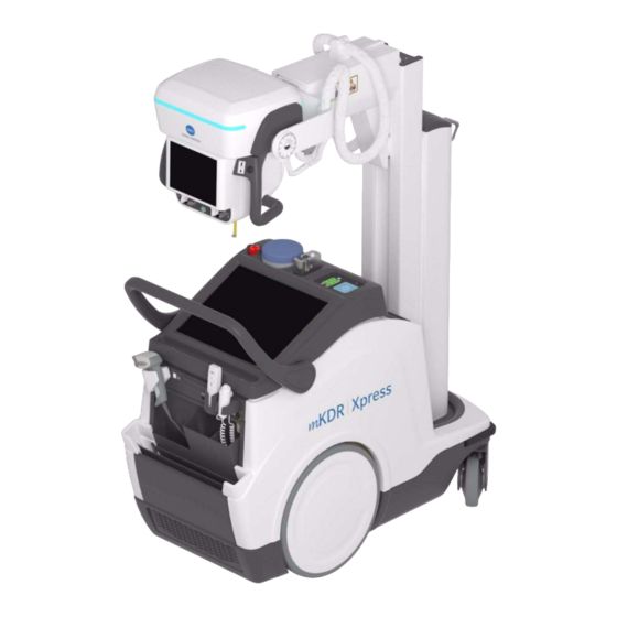
- Page 1 Operation Digital Mobile X-ray Unit KONICA MINOLTA mKDR Xpress Technical Publication OM-0481R1_EN_KON...
- Page 2 28110 Algete, Madrid -- España (Spain) Tel: +34 916 280 544 Fax: +34 902 190 385 www.sedecal.com Manufactured by SEDECAL for KONICA MINOLTA HEALTHCARE AMERICAS, INC 411 Newark Pompton Turnpike Wayne, NJ 07470 -- USA Tel: +1 800 366 5343 E-mail: DRSystems@gcp.konicaminolta.com...
- Page 3 Mobile X-ray Unit Operation REVISION HISTORY REVISION DATE REASON FOR CHANGE OCT 01, 2021 First Edition. MAR 08, 2022 Manual Cover and some rendered images have been updated. New Section: Appendix C -- Administrator User. Updated Sections: Safety Symbols, Mains Connection, Smart ON/OFF System: ON/OFF Button + RFID System, Infrared Remote Control, Manual Clutch Screws, Collimator Movements, 3.7...
- Page 4 Mobile X-ray Unit Operation ADVISORY SYMBOLS The following advisory symbols will be used throughout this manual. Their application and meaning are described below. DANGERS ADVISE OF CONDITIONS OR SITUATIONS THAT IF NOT HEEDED OR AVOIDED WILL CAUSE SERIOUS PERSONAL INJURY OR DEATH. ADVISE OF CONDITIONS OR SITUATIONS THAT IF NOT HEEDED OR AVOIDED COULD CAUSE SERIOUS PERSONAL INJURY,...
-
Page 5: Table Of Contents
Mobile X-ray Unit Operation TABLE OF CONTENTS Section Page INTRODUCTION ............General Features . -
Page 6: Section Page
Mobile X-ray Unit Operation Section Page 2.10 Quantitative Information ..........2.10.1 Functional Tests Performed to Obtain the Quantitative Information 2.11 Deterministic Effects . - Page 7 Mobile X-ray Unit Operation Section Page DAP Chamber (Option) ..........Focal-Skin Distance Sensor (Option) .
- Page 8 Mobile X-ray Unit Operation Section Page PERIODIC MAINTENANCE ..........Operator Tasks .
-
Page 9: Introduction
Mobile X-ray Unit Operation SECTION 1 INTRODUCTION This manual contains all the information necessary to understand and operate the Mobile X-ray Units. It provides a general description, safety and regulatory information, operating instructions and specifications concerning the system. It is not intended to teach radiology or to take any type of clinical diagnosis. This Unit is designed for general radiography. - Page 10 Mobile X-ray Unit Operation X-RAY GENERATION COMPONENTS Control Console. Ultra software application for image acquisition. Generator, that comprises: Power Module, containing power and control components. Battery Module, with batteries and charge/control components. Radiogenic unit, part of the Head-Assembly, that comprises: ...
-
Page 11: General Features
Mobile X-ray Unit Operation GENERAL FEATURES The main features of this Unit are: A solid and ergonomic design. Ease of operation; security and precision of all positioning movements relative to the patient. Standard electrical outlet operation with single-phase lines ... -
Page 12: Product Identification
Mobile X-ray Unit Operation PRODUCT IDENTIFICATION To provide manufacturer and product information, each major item in the equipment has identification labels attached. The labels contain the following information: Product and Model. Reference and Type. Date of manufacture. Serial number. -
Page 13: Indications For Use
Mobile X-ray Unit Operation INDICATIONS FOR USE 1.3.1 INTENDED USE This is a Digital Mobile Diagnostic X-ray System intended for use by a qualified/trained doctor or technician on both adult and pediatric subjects for taking diagnostic radiographic exposures of the skull, spinal column, chest, abdomen, extremities, and other body parts. -
Page 14: Applied Parts
Mobile X-ray Unit Operation APPLIED PARTS Applied Parts refer to parts of Medical equipment that in Normal Use necessarily comes into physical contact with the patient for Medical equipment to perform its function. This RAD equipment includes the following Applied Parts: Digital Detectors. -
Page 15: Safety And Regulatory Information
Mobile X-ray Unit Operation SECTION 2 SAFETY AND REGULATORY INFORMATION This section describes the safety considerations, general precautions for patient, operator and equipment in order to perform a safe operation and service tasks. Regulatory information and symbols used in the equipment are detailed in this section to operate it safely. - Page 16 Mobile X-ray Unit Operation OPERATOR AND SERVICE PERSONNEL AUTHORIZED TO USE, INSTALL, CALIBRATE MAINTAIN THIS EQUIPMENT MUST BE AWARE OF THE DANGER OF EXCESSIVE EXPOSURE TO X-RAY RADIATION. IT IS VITALLY IMPORTANT THAT EVERYONE WORKING WITH X-RAY RADIATION IS PROPERLY TRAINED, INFORMED ON THE HAZARDS OF RADIATION AND TAKE ADEQUATE STEPS TO ENSURE PROTECTION AGAINST INJURY.
- Page 17 Mobile X-ray Unit Operation SPECIAL ATTENTION MUST BE GIVEN TO DIAGNOSTIC X-RAY EQUIPMENT SPECIFIED USED COMBINATION WITH ACCESSORIES OR OTHER ITEMS. BE AWARE OF POSSIBLE ADVERSE EFFECT ARISING FROM THESE MATERIALS LOCATED IN THE X-RAY BEAM (SEE THE TABLE BELOW MAXIMUM EQUIVALENT ATTENUATION OF MATERIALS POSSIBLY LOCATED IN THE...
-
Page 18: Responsibilities
Mobile X-ray Unit Operation RESPONSIBILITIES THIS X-RAY UNIT MAY BE DANGEROUS TO PATIENT AND OPERATOR UNLESS SAFE EXPOSURE FACTORS, OPERATING INSTRUCTIONS MAINTENANCE SCHEDULES ARE OBSERVED. THE EQUIPMENT HEREIN DESCRIBED IS SOLD WITH THE UNDERSTANDING THAT MANUFACTURER, AGENTS, AND REPRESENTATIVES ARE NOT LIABLE FOR INJURY OR DAMAGE WHICH... -
Page 19: Maximum Permissible Dose (Mpd)
Mobile X-ray Unit Operation RESPONSIBILITY PURCHASER /CUSTOMER TO PROVIDE THE MEANS FOR AUDIO AND VISUAL COMMUNICATION BETWEEN THE OPERATOR AND THE PATIENT. IT IS THE RESPONSIBILITY OF THE OPERATOR TO ENSURE THAT ALL THE EXPOSURE PARAMETERS ARE CORRECT BEFORE PERFORMING AN EXAM TO THE PATIENT, BY VERIFYING THAT THE PARAMETER SELECTION HAS NOT BEEN MODIFIED UNINTENTIONALLY OR BY THE CONTACT OF EXTERNAL ELEMENTS ON THE CONTROL CONSOLE, IN... -
Page 20: Radiation Protection
Mobile X-ray Unit Operation RADIATION PROTECTION Although this equipment is built to the highest safety standards and incorporates a high degree of protection against X-ray radiation other than the useful beam, no practical design of equipment can provide complete protection, nor can any practical design compel the operator to take adequate precautions to prevent the possibility of any persons carelessly, unwisely, or unknowingly exposing themselves or others to X-ray radiation. - Page 21 Mobile X-ray Unit Operation Observe the following rules for radiation protection of the personnel in the examination room during X-ray exposures: - Wear radiation protective clothing. - Wear a personal dosimeter. - Use the different recommended protective materials and devices against radiation. - While operating or servicing X-ray equipment, always keep as large a distance as possible from the Focal Spot and X-ray beam, never shorter than 2 meters, protect body and do not...
-
Page 22: Monitoring Of Personnel
Mobile X-ray Unit Operation MONITORING OF PERSONNEL Monitoring of personnel to determine the amount of radiation to which they have been exposed provides a valuable cross check to determine whether or not safety measures are adequate. It may reveal inadequate or improper radiation protection practices and potentially serious radiation exposure situations. -
Page 23: Safety Symbols
Mobile X-ray Unit Operation SAFETY SYMBOLS The following safety symbols may appear in the equipment. Their meaning are described below. Caution. Consult accompanying documents. Safety Symbol. Follow instructions for use, especially those instructions identified with Advisory Symbols to avoid any risk for the Patient or Operator. - Page 24 Mobile X-ray Unit Operation General Mandatory action. Type B applied part. Protection against harmful ingress of water or particulate matter. IP Classification: Ordinary. Ionizing radiation. Non-ionizing electromagnetic radiation. Radiation of Laser apparatus. Do not stare into beam. (Only applicable to equipment with Laser Pointer) Dangerous voltage.
- Page 25 Mobile X-ray Unit Operation Warning: Non-ionizing radiation. Warning: Laser beam. Warning: Electricity. Warning: Do not place fingers between mobile and fixed parts of the equipment, it may cause serious injuries to patient or operator. As well, make sure the patient extremities are correctly positioned into limit areas during operation, movement of parts may cause serious damages to patient.
- Page 26 Mobile X-ray Unit Operation Emergency stop. Stand-By (Only applies to IEC 60601-1:2005, IEC 60601-1:2005+AMD1:2012) “ON” power. “OFF” power. “ON” / “OFF” (push-push). Each position, “ON” or “OFF”, is a stable position. Alternating current. Three-phase alternating current. Three-phase alternating current with neutral conductor. Connection point for the neutral conductor on Permanently Installed equipment.
- Page 27 Mobile X-ray Unit Operation Direct current. Both direct and alternating current. Protective Earth (Ground). Earth (Ground). This symbol according to the European Directive indicates that the Waste of Electrical and Electronic Equipment (WEEE) must not be disposed of as unsorted municipal waste and must be collected separately.
-
Page 28: Regulatory Information
Mobile X-ray Unit Operation REGULATORY INFORMATION 2.7.1 CERTIFICATIONS The Mobile X-Ray Unit covered by this Operation Manual complies with the following certifications: Statement of Compliance with IEC 60601-1-3: Mobile X-Ray Unit with radiation protection in accordance with IEC 60601-1-3: 1994 and IEC 60601-1-3: 2008 and IEC 60601-1-3:2008+AMD1:2013 . -
Page 29: Protection Against Electric Shock Hazards
Mobile X-ray Unit Operation 2.7.4 PROTECTION AGAINST ELECTRIC SHOCK HAZARDS Protection against electric shock hazards in accordance with Standards: IEC 60601-1:1988, IEC 60601-1:2005 and IEC 60601-1:2005+AMD1:2012, IEC 60601-2-54:2009 and IEC 60601-2-54:2009+AMD1:2015. This equipment has been classified as a type-B ( ) device, in accordance with Standard IEC 60601-1 requirements: Class I - Type B applied parts. -
Page 30: Designated Significant Zones Of Occupancy
Mobile X-ray Unit Operation 2.7.8 DESIGNATED SIGNIFICANT ZONES OF OCCUPANCY X-Ray equipment specified for any radiological examination that requires the operator or staff to be close to the patient during normal use (a.e. some pediatric examinations or other types of examinations for patients that may require assistance), shall have at least one “Significant Zone of Occupancy”... - Page 31 Mobile X-ray Unit Operation Illustration 2-2 Radiographic Examination on any Patient Support or any Table Focal Spot MOBILE X-RAY UNIT Phantom X-ray Receptor Patient Support RAD TABLE S = SIGNIFICANT ZONE OF OCCUPANCY MINIMUM AREA 60 x 60 cm MINIMUM HEIGHT ABOVE THE FLOOR 200 cm Focal Spot Dosimeter SIGNIFICANT ZONE OF OCCUPANCY...
-
Page 32: Distribution Of Stray Radiation
Mobile X-ray Unit Operation 2.7.9 DISTRIBUTION OF STRAY RADIATION Measurement conditions to determine the distribution of Stray Radiation in the Significant Zone of Occupancy are in accordance with IEC 60601-1-3:1994, IEC 60601-1-3:2008 and IEC 60601-1-3:2008+AMD1:2013. Exposure Parameters: RAD mode, 150 kVp, 10 mAs. ... - Page 33 Mobile X-ray Unit Operation Illustration 2-3 Distribution of Stray Radiation on the Chest Unit or Front Panel 1000 1500 2000 2500 3000 3500 4000 4500 5000 5500 6000 6500 7000 7500 STRAY RADIATION (μGy/h) d = 50 cm d = 100 cm d = 50 cm d = 100 cm Protective Device...
- Page 34 Mobile X-ray Unit Operation Illustration 2-4 Distribution of Stray Radiation on any Patient Support or any Table 500 1000 1500 2000 2500 3000 3500 4000 4500 5000 5500 6000 6500 7000 7500 8000 8500 9000 950010000 STRAY RADIATION (μGy/h) SIGNIFICANT ZONE OF OCCUPANCY AT THE RIGHT SIDE OF THE MOBILE UNIT (CATHODE) d = 50 cm...
-
Page 35: Electromagnetic Compatibility (Emc)
Mobile X-ray Unit Operation ELECTROMAGNETIC COMPATIBILITY (EMC) This equipment generates, uses, and can radiate radio frequency energy. The equipment may cause radio frequency interference to other medical non-medical devices radio communications. To provide reasonable protection against such interference, this equipment complies with emissions limits for a Group 1 -- Class A Medical Devices as stated in EN 60601-1-2: 2007 and IEC 60601-1-2:2014. - Page 36 Mobile X-ray Unit Operation It is customer/owner responsibility to assure that this equipment and vicinity equipment complies the value of radio frequency interferences shown in General Regulation safety according IEC 60601-1-2: 2007 IEC 60601-1-2:2014 Tables as described in this section. The manufacturer is not responsible for any interference caused by using other than recommended interconnect cables or by unauthorized changes or modifications to this...
- Page 37 Mobile X-ray Unit Operation GUIDANCE AND MANUFACTURER’S DECLARATION - ELECTROMAGNETIC EMISSIONS (IEC 60601-1-2:2007 AND IEC 60601-1-2:2014) This X-ray System is intended for use in the electromagnetic environment specified below. The customer or user of this X-ray System should assure that it is used in such an environment. Emissions test Compliance Electromagnetic environment - - guidance...
- Page 38 Mobile X-ray Unit Operation GUIDANCE AND MANUFACTURER’S DECLARATION - ELECTROMAGNETIC IMMUNITY (IEC 60601-1-2:2007) This X-ray System is intended for use in the electromagnetic environment specified below. The customer or user of this X-ray System should assure that it is used in such an environment. IEC 60601-1-2:2007 Compliance Immunity Test...
- Page 39 Mobile X-ray Unit Operation GUIDANCE AND MANUFACTURER’S DECLARATION - ELECTROMAGNETIC IMMUNITY (IEC 60601-1-2:2007) This X-ray System is intended for use in the electromagnetic environment specified below. The customer or user of this X-ray System should assure that it is used in such an environment. IEC 60601-1-2:2007 Compliance Immunity Test...
- Page 40 Mobile X-ray Unit Operation RECOMMENDED SEPARATION DISTANCES BETWEEN PORTABLE AND MOBILE RF COMMUNICATIONS EQUIPMENT AND THE X-RAY SYSTEM (IEC 60601-1-2:2007) This X-ray System is intended for use in an electromagnetic environment in which radiated RF disturbances are controlled. The customer or user of this X-ray System can help prevent electromagnetic interference by maintaining a minimum distance between portable and mobile RF communications equipment (transmitters) and this X-ray System as recommended below, according to the maximum output power of the communications equipment.
- Page 41 Mobile X-ray Unit Operation GUIDANCE AND MANUFACTURER’S DECLARATION - ELECTROMAGNETIC IMMUNITY (IEC 60601-1-2:2014) This X-ray System is intended for use in the electromagnetic environment specified below. The customer or user of this X-ray System should assure that it is used in such an environment. IEC 60601-1-2:2014 Electromagnetic Immunity Test...
- Page 42 Mobile X-ray Unit Operation GUIDANCE AND MANUFACTURER’S DECLARATION - ELECTROMAGNETIC IMMUNITY (IEC 60601-1-2:2014) This X-ray System is intended for use in an electromagnetic environment specified below. The customer or user of this X-ray System should assure that it is used in such an environment. IEC 60601-1-2:2014 Electromagnetic Immunity Test...
- Page 43 Mobile X-ray Unit Operation IMMUNITY REQUIREMENTS TO RF WIRELESS COMMUNICATIONS EQUIPMENT (IEC 60601-1-2:2014) This X-ray System is intended for use in an electromagnetic environment specified below. The customer or User of this X-ray System should assure that it is used in such an environment. Band Distance Immunity Test Level...
-
Page 44: Radio Frequency Interference Notice (Usa)
Mobile X-ray Unit Operation RADIO FREQUENCY INTERFERENCE NOTICE (USA) This equipment has been tested and found to comply with the limits for a Class A digital device, pursuant to Part 15 of the FCC Rules. These limits are designed to provide reasonable protection against harmful interference when the equipment is operated in a commercial environment. -
Page 45: 2.10 Quantitative Information
Mobile X-ray Unit Operation 2.10 QUANTITATIVE INFORMATION The following tables show the Quantitative Information associated Note this equipment according with Standard IEC 60601-1-3:2008 and IEC 60601-1-3:2008+AMD1:2013. This information illustrates loading factors for image performance and supplies Dose indication examples. Therefore, these tables are an instance of the adjustment of Loading Factors, Focal Spot Selection, SID and Collimator opening, which affect to the radiation quality or to the radiation dose rate applied in normal use. - Page 46 Mobile X-ray Unit Operation Quantitative Information Loading Factors Parameter Selection Measured Doses Patient examination (orientative) CHEST AP 0.020 Small 35 x 43 22.39 11035 69.97 NECK 0.020 Small 24 x 30 96.10 8870 88.70 ABDOMEN AP 0.025 Large 35 x 43 69.72 31300 78.25...
-
Page 47: 2.11 Deterministic Effects
Mobile X-ray Unit Operation 2.11 DETERMINISTIC EFFECTS Deterministic effects may occur when the Radiation dose to a certain organ or tissue exceeds a specific threshold. Particular organs or tissues of such concern in diagnostic Radiology are the skin and the eye lens. The numerical value of the threshold dose is in the range between 1 Gy and 3 Gy. - Page 48 Mobile X-ray Unit Operation This page intentionally left blank. OM-0481R1...
-
Page 49: General And Motion Controls
Mobile X-ray Unit Operation SECTION 3 GENERAL AND MOTION CONTROLS Operation is carried out from the different controls: Control Panel, with controls to turn ON/OFF the system, System ON/OFF Indicator, Battery Charge Level Indicator, Emergency Switch OFF. Control Console Screen; Head-Assembly Screen. ... - Page 50 Mobile X-ray Unit Operation Illustration 3-1 Mobile X-ray unit: General Features Head-Assembly Handlebar Front Wheel Status Light Indicator Connections Panel Anti-Collision Bumper Handgrips Handswitch Power Line Plug Head Assembly Screen (option) Infrared Remote Control (option) Detector Storage/Charge Collimator Panel (option) Barcode Scanner Parking System Motion Controls (on the Handgrips)
- Page 51 Mobile X-ray Unit Operation Illustration 3-2 Mobile X-ray unit OM-0481R1...
-
Page 52: Mains Connection
Mobile X-ray Unit Operation MAINS CONNECTION The Unit should be plugged into a wall socket compliant with local regulations and electrical requirements of the equipment. The plug is the device used as a means of disconnecting the Unit from mains. Position the Unit so that the plug can be easily disconnected. - Page 53 Mobile X-ray Unit Operation WHEN NOT GENERATING X-RAYS, KEEP THE UNIT CONNECTED TO THE MAINS, EVEN WHEN BATTERIES ARE FULLY CHARGED. THIS ENSURES MAXIMUM STORAGE ENERGY. Connect the Power Line Cable to the mains in order to allow the Charging Circuits to charge the Batteries.
-
Page 54: Control Console
Mobile X-ray Unit Operation CONTROL CONSOLE SMART ON/OFF SYSTEM: ON/OFF Button + ON/OFF Button + RFID System Keypad System 1.2.3 1.2.2 1.2.1 1.2.4 Control Console 1.2.3 Battery Charge Level Indicators Control Panel 1.2.4 Emergency Switch Off 1.2.1 On/Off Control Main Screen 1.2.2 System On/Off Indicator Pencil Tray OM-0481R1... - Page 55 Mobile X-ray Unit Operation The following icons can be displayed on the Control Panel: " ON/OFF The ON/OFF button icon enables the user to ON/OFF the unit. Refer to Sections 3.2.1.1 and 3.2.1.2. " RFID symbol The ON/OFF button with the RFID Card Reader symbol (RFID- -Radio Frequency IDentification) enables the user to ON/OFF and access the system with the RFID Card.
-
Page 56: System On
Mobile X-ray Unit Operation 3.2.1 SYSTEM ON The ON/OFF controls are the means to turn the unit ON and OFF. The unit can operate in Stand-Alone mode, that is, operating Note without mains being present or unplugged from mains. Do not touch any system control during the starting up process;... -
Page 57: Smart On/Off System: On/Off Button + Rfid System
Mobile X-ray Unit Operation 3.2.1.1 SMART ON/OFF SYSTEM: ON/OFF BUTTON + RFID SYSTEM To turn the unit ON, proceed as described in the following steps: Press and hold the ON/OFF button (1) for a few seconds; the System ON/OFF Indicator (2) will blink white for 5 seconds. When the Mobile Unit is in Charging Mode it is not necessary to Note press the ON/OFF button in the first instance. - Page 58 Mobile X-ray Unit Operation The RFID Card is detected automatically by the system. Note Depending on the system permissions assigned to each RFID Card, the user can perform the following actions: Movements: It allows the user to drive the system in Parking position. When the system is out of the Parking position, it allows the user to move the Column and the Arm in order to put the system in parking position.
- Page 59 Mobile X-ray Unit Operation Each mobile unit is provided with several different RFID cards: MOVEMENTS RFID Cards, with permission for: Movements. OPERATOR RFID Cards, with permission for: Movements. Panel Out. X-rays (Radiographic Operation). ADMINISTRATOR RFID Card, with permission for: ...
-
Page 60: On/Off Button + Keypad System
Mobile X-ray Unit Operation 3.2.1.2 ON/OFF BUTTON + KEYPAD SYSTEM To turn the unit ON, proceed as described in the following steps: Press and hold the ON/OFF button (1) for a few seconds; the System ON/OFF Indicator (2) will blink white for 5 seconds. Enter the four-digit Access Code into the Keypad (3), within 5 seconds from turning the unit ON, and press the OK button (4);... -
Page 61: System Off
Mobile X-ray Unit Operation 3.2.2 SYSTEM OFF Place the unit in the Parking position right after turning the system OFF since positioning controls will remain enabled for 15 seconds approximately. After turning OFF the unit, wait at least 10 seconds before turning Note it ON again. -
Page 62: Emergency Stop
Mobile X-ray Unit Operation 3.2.3 EMERGENCY STOP In the event of an emergency, the unit is turned OFF by forcibly pressing this switch (red mushroom-shaped switch). The switch is protected by the Cover, in order to prevent it from being accidentally pressed. The Emergency Stop must not be used to switch OFF the unit, in order to avoid damaging the software. -
Page 63: System On/Off Indicator
Mobile X-ray Unit Operation 3.2.5 SYSTEM ON/OFF INDICATOR The system ON/OFF Indicator (1) is on the Control Panel, over the Battery Charge Level Indicators. The System ON/OFF Indicator lights up in different colors, indicating different system status: COLORS SYSTEM STATUS SYSTEM OFF The ON/OFF Indicator is not illuminated when the system is OFF. -
Page 64: Control Console
Mobile X-ray Unit Operation 3.2.6 CONTROL CONSOLE The Control Console houses the Main Screen which consists of a 19” capacitive Touchscreen Monitor, with pinch and zoom functionalities. Konica-Minolta “Ultra” Software Application is shown on the Main Screen, including the RAD Screen (Generator Control Panel) with the controls, indicators and displays needed to perform radiographic exams. -
Page 65: Battery Charge Level Indicators
Mobile X-ray Unit Operation 3.2.7 BATTERY CHARGE LEVEL INDICATORS The column with the Exposure symbol indicates the charge level of the Batteries used for radiographic operations (X-ray exposures) and the column with the Mobile X-Ray unit symbol indicates the charge level of the Batteries used for the Mobile motion (motors). - Page 66 Mobile X-ray Unit Operation Both columns comprise three Indicators, representing a battery status as described below: Battery Full, Medium, Low, Very Low and Critically Low. MOBILE unit IN CHARGING MODE MOBILE unit IN STAND-ALONE MODE (PLUGGED TO MAINS) (UNPLUGGED FROM MAINS) LED INDICATORS AND STATUS LED INDICATORS AND STATUS Full Charge:...
-
Page 67: Battery State Alerts
Mobile X-ray Unit Operation 3.2.8 BATTERY STATE ALERTS The following functions may be configured by the Service Note Engineer. For further information, refer to Section 4 of Control Console and Section 5 of System Messages. The Following Battery State Alerts can be displayed on the RAD screen: "... - Page 68 Mobile X-ray Unit Operation " Battery Critical Low: This alert appears when the system batteries are at Critically Low Charge status. The lower indicator flashes orange, on one or both columns, and the middle and upper indicators are off, with the unit disconnected from mains (not charging). This alert indicates that it is necessary to connect the system to a power source for battery charging, although the operation is limited: If the indicator is on the X-ray column, indicates that exposures are...
-
Page 69: Power Off Settings
Mobile X-ray Unit Operation 3.2.9 POWER OFF SETTINGS Power OFF settings can be configured by the User Administrator Note or the Service Engineer. " Time Out Switch Off Pressed. Time set by default:: 3 seconds. Press and hold the Switch OFF button for 3 seconds; the system will start the turning OFF process. -
Page 70: Status Light Indicator (Option)
Mobile X-ray Unit Operation 3.2.10 STATUS LIGHT INDICATOR (OPTION) The system can be provided with the Status Light Indicator (1), located at the Head Assembly, which indicates different system status by colors, as described in the following table. OM-0481R1... - Page 71 Mobile X-ray Unit Operation COLORS SYSTEM STATUS SYSTEM STATUS NOT MOVING MOVING SYSTEM STANDBY X-rays are disabled. The Status Light Indicator is OFF when the system is in Standby. LIGHT OFF BLINKS WHITE It blinks white when the system is moving. SYSTEM READY FOR EXPOSURE The Status Light Indicator lights solid cyan when the system is ready, i.e., the user only needs to press the Handswitch for making an exposure: the Detector is ready, the RAD...
-
Page 72: Connections Panel
Mobile X-ray Unit Operation CONNECTIONS PANEL DO NOT CONNECT ANY ACTIVE DEVICES THAT APPLY EXTERNAL VOLTAGE TO THE SYSTEM THROUGH THE USB PORTS; ONLY PASSIVE DEVICES CAN BE CONNECTED. The Mobile unit is provided with a Connections Panel with: Hand Switch (HS), HS Connector, HS Support, (Refer to Section 3.4). Infrared Remote Control (option), (Refer to Section 3.5). -
Page 73: X-Ray Handswitch
Mobile X-ray Unit Operation X-RAY HANDSWITCH Radiographic exposures are controlled with the “Prep” (preparation) and “Exp” buttons on the X-ray Handswitch. The status of the exposure is shown by the “Ready” and “X-ray On” indicators for the duration of the exposure. PREP: Press the Handswitch button half-way (“Prep”... -
Page 74: Infrared Remote Control (Option)
Mobile X-ray Unit Operation INFRARED REMOTE CONTROL (OPTION) The unit cannot perform exposures when the Column is in Parking Note position; it only can perform exposures out of the Parking position. DURING AN EXPOSURE, THE IR REMOTE CONTROL MUST BE POINTED DIRECTLY AT THE MOBILE UNIT AT ALL TIMES. The Infrared Remote Control permits the operator to perform exposures at a distance from the X-ray beam (Head-Assembly) to protect against radiation. - Page 75 Mobile X-ray Unit Operation Take the Remote Exposure Control device out of its cradle. Aim the Remote Control at the IR Receiver Sensor on the Mobile unit from a maximum distance of 10 meters. OFF / Prep / Exp Collimator Light Status LED COLLIMATOR LIGHT BUTTON: Press this push-button to turn on the Collimator Light.
-
Page 76: Motion Controls
Mobile X-ray Unit Operation MOTION CONTROLS DRIVE THE UNIT WITH THE ARM IN PARKING POSITION. WHEN NOT IN PARKING POSITION, MOVEMENT VELOCITY IS REDUCED SIGNIFICANTLY. FOR SAFETY REASONS, DO NOT DRIVE THE UNIT OVER RAMPS WITH AN INCLINATION ANGLE >8 TO AVOID THE RISK OF OVERBALANCE, THE MOBILE UNIT MUST NOT BE IN STATIONARY POSITION ON SURFACES WITH THE FOLLOWING INCLINATION ANGLES:... - Page 77 Mobile X-ray Unit Operation MONITOR WITH SPECIAL CARE THE PATIENT POSITION OR ANYONE PRESENT, TO AVOID INJURY CAUSED BY UNIT MOVEMENTS. INTRAVENOUS TUBING, CATHETERS AND OTHER PATIENT CONNECTED LINES SHOULD BE ROUTED AWAY FROM MOVING EQUIPMENT. ALWAYS USE THE HAND-GRIPS OF THE HEAD-ASSEMBLY TO CONTROL AND DRIVE THE COLUMN AND ARM MOVEMENTS, NEVER...
-
Page 78: Displacement Controls
Mobile X-ray Unit Operation 3.6.1 DISPLACEMENT CONTROLS Displacement cannot be performed when the unit is connected to Note mains. Velocity and visual signals (Status Light Indicator) can be Note configured by the Service Engineer. 3.6.1.1 HANDLEBAR The unit is driven by holding the Handlebar with the hands, and it stops when the Handlebar is released by the user. -
Page 79: Fine Positioning Controls
Mobile X-ray Unit Operation 3.6.1.2 FINE POSITIONING CONTROLS Fine Positioning Controls permit the fine positioning adjustment of the system respecting the patient, with the operator positioned opposite the Head-Assembly. The buttons with the arrow icons located on each Handgrip, control the motion of each driving wheel independently, at low speed, backward/forward. - Page 80 Mobile X-ray Unit Operation The illustration below, details the corresponding movements. The buttons correspond to each motor and do not change when the unit is in Parking Position. Illustration 3-3 Fine Positioning Controls RB = Right Back RF = Right Front LF = Left Front LB = Left Back OM-0481R1...
-
Page 81: Manual Clutch Screws
Mobile X-ray Unit Operation 3.6.1.3 MANUAL CLUTCH SCREWS When the unit has to be moved manually, the (x2) Clutch Screws (Allen type) located on each wheel must be removed using the tools provided with the unit. DRIVE THE UNIT MANUALLY ONLY WHEN MOTORIZED MOTIONS CANNOT BE PERFORMED (DUE TO A SYSTEM MALFUNCTION OR THE BATTERIES DISCHARGE). -
Page 82: Proximity Sensors
Mobile X-ray Unit Operation Use the Allen Wrench to remove the Clutch Screws (x2) of each wheel. This will uncouple the wheels from the motors (releasing the brakes) allowing the free motion of the unit. Clutch Screws (circled) Magnetic Hubcap 3.6.1.4 PROXIMITY SENSORS PROXIMITY SENSORS ARE NOT A SAFETY SYSTEM OR AN... -
Page 83: Bumpers
Mobile X-ray Unit Operation 3.6.1.5 BUMPERS The Front Bumper is provided with several sensors that stop the motor movement in the event of a frontal collision. The Status Light Indicator lights magenta when the Front Bumper is activated. The Front Bumper is automatically deactivated by using the system motion controls backwards;... -
Page 84: Parking Position Of The Arm
Mobile X-ray Unit Operation 3.6.2 PARKING POSITION OF THE ARM The unit is in Parking Position when the Parking Detent is secure in the Catch. Place the Arm in Parking Position as follows: Fully retract the Telescopic Arm and turn the Column until the Parking ... -
Page 85: Movement Controls
Mobile X-ray Unit Operation 3.6.3 MOVEMENT CONTROLS 3.6.3.1 COLUMN AND TELESCOPIC ARM MOVEMENTS Head-Assembly Handgrips have a Brake Control that releases or locks Column rotation and vertical and telescopic Arm movements. This control also releases the Arm Catch when in Parking position. 1 Handgrips Hold the Handgrips to activate the Brake Control to move the Column and Arm until the Head-Assembly is positioned. -
Page 86: Head-Assembly Movements
Mobile X-ray Unit Operation 3.6.3.2 HEAD-ASSEMBLY MOVEMENTS Press the black buttons located on the Handgrips to rotate the Head-Assembly from its vertical position: on its transversal axis, i. e. roll rotation (see Illustration 3-5, A). ¦180 This movement has detents at --90 and +90 , and at --180 and 180... -
Page 87: Collimator Movements
Mobile X-ray Unit Operation 3.6.3.3 COLLIMATOR MOVEMENTS The Collimator can rotate ¦90_ on its vertical axis (refer to Illustration 3-5,C), while the Head-Assembly remains in the same position. This movement is performed by manually turning the Collimator and has detents at --90 and +90 Due to geometric restrictions related to the anode angle of the Note... -
Page 88: Collimator Controls
Mobile X-ray Unit Operation COLLIMATOR CONTROLS Collimator Light Measuring Tape Handgrips Collimator Knobs Refer to the Collimator Manual for extended information about Note operation or technical description needed to maintain compliance with Standard IEC 60601-1-3:2008. The Mobile unit is supplied with the following Collimator: Collimator Type Manual Collimator with front and rear side Knobs, double Laser, Motorized Filters and ready for both Estimated Dose (EDAP) option and DAP Chamber option... - Page 89 Mobile X-ray Unit Operation The Collimator has the following functions: Collimator LED Light push-button. Press once the Collimator Light push-button to turn the light ON; it will remain ON for a few seconds before automatically switching OFF. Collimator light may also be switched ON/OFF by clicking the Collimator Light push-button located at the Handswitch.
-
Page 90: Dap Chamber (Option)
Mobile X-ray Unit Operation Additional Variable Filtration with the following Motorized Filters: 0 mm AL 1 mm Al + 0.1 mm Cu 1 mm Al + 0.2 mm Cu 2 mm Al Select the filtration option on the Head-Assembly Screen. External Filtration. -
Page 91: Focal-Skin Distance Sensor (Option)
Mobile X-ray Unit Operation FOCAL-SKIN DISTANCE SENSOR (OPTION) The FSD (Focal-Skin Distance) sensor is installed at the front of the underside of the Collimator. It reads the distance from the focus of the tube to the surface of incidence on a patient, measured along the beam axis. The measured value is displayed on the Head-Assembly Console (refer to Section 4.2.13). -
Page 92: 3.10 Wireless Digital Detectors, Options And Accessories
Mobile X-ray Unit Operation 3.10 WIRELESS DIGITAL DETECTORS, OPTIONS AND ACCESSORIES Wireless Digital Detectors: AeroDR 2 1417HQ, AeroDR 2 1417S, AeroDR 3 1717HD, AeroDR 3 1417HD, AeroDR 3 1012HQ Some Wireless Digital Detectors can be fitted in an optional Detector Handle Support with an Antiscatter Grid. -
Page 93: Wireless Digital Detectors
Mobile X-ray Unit Operation 3.10.1 WIRELESS DIGITAL DETECTORS Wireless Digital Detectors communicate with the Mobile unit through the internal Access Point. Wireless Digital Detector configuration can include a built-in Detector Battery Charger (option), and a Back-up Cable. AeroDR 2 1417HQ AeroDR 2 1417S AeroDR 3 1717HD AeroDR 3 1417HD... -
Page 94: Detector Back-Up Communication Cable (Option)
Mobile X-ray Unit Operation 3.10.2 DETECTOR BACK-UP COMMUNICATION CABLE (OPTION) Detector Back-up Communication Cable (1) allows to expand the Wireless Digital Detector, from wireless to wired configuration. Connect the Cable to the Detector and to the connector at the Front Cover (2). When not in use, the Back-up Cable can be stored at the Detector Holders. -
Page 95: General Use And Maintenance Of Wireless Digital Detectors, Options And Accessories
Mobile X-ray Unit Operation 3.10.4 GENERAL USE AND MAINTENANCE OF WIRELESS DIGITAL DETECTORS, OPTIONS AND ACCESSORIES The action of the Air-Conditioning or Heating may produce condensation in the equipment, wait until the condensation evaporates before performing an exposure. As a general rule, raise or lower the room temperature gradually to avoid condensation. - Page 96 Mobile X-ray Unit Operation This page intentionally left blank. OM-0481R1...
-
Page 97: Control Console
Mobile X-ray Unit Operation SECTION 4 CONTROL CONSOLE All controls, indicators and displays located on the Control Console are positioned depending upon their functions. Use the operating controls as described in this manual. Any other Note non-indicated combination may cause an incorrect operation. MAIN SCREEN Konica-Minolta “Ultra”... -
Page 98: Head-Assembly Console
Mobile X-ray Unit Operation HEAD-ASSEMBLY CONSOLE The Head-Assembly Console displays the Radiographic Parameters, System Messages and some other useful information for the operator. Illustration 4-2 Head-Assembly Console Parking Position Heat Units System Status and Patient Information Motion Speed Battery Charge Level Exposure Indicator Rotation and angulation angles... -
Page 99: Heat Units Indicator
Mobile X-ray Unit Operation EXPOSURE: Indicates that the X-ray exposure is in progress. It remains illuminated during the length of exposure. At the same time that radiographic exposure is being made, an audible signal sounds. INHIBITION CONDITIONS (ENABLED FILAMENTS): There are one or more reasons causing an inhibition of exposure, despite the Tube Filaments being properly enabled. -
Page 100: Batteries Status
Mobile X-ray Unit Operation 4.2.3 BATTERIES STATUS Full Charge (Stand- -alone mode): The Battery icons are displayed in steady green when the battery charge levels for X-ray and Motion are between 60% and 100%, and the unit is unplugged from mains. Full Charge (Charging mode): The Battery icons are displayed in steady green when the battery charge levels for X-ray and Motion are between 60% and 100%, and the unit is plugged to mains. -
Page 101: Parking Indicator
Mobile X-ray Unit Operation Very Low Charge (Charging mode): The Battery icons are displayed in steady green when the battery charge levels for X-ray and Motion are between 1% and 19%, and the unit is plugged to mains. The “Lightning” icon indicates that the batteries are charging. Critically Low Charge (Stand- -alone mode): The Battery icons are displayed in blinking orange when the battery charge level for X-ray and Motion is 0%, and the unit is unplugged from mains. -
Page 102: Mute Button
Mobile X-ray Unit Operation 4.2.6 MUTE BUTTON This button displays the selected sound option. Press on it to activate/deactivate the acoustic signals of the Mobile Unit. 4.2.7 USER ACTION Active when manual adjustments from the operator are required before making the exposure (e.g. -
Page 103: Radiographic Parameters
Mobile X-ray Unit Operation 4.2.9 RADIOGRAPHIC PARAMETERS Radiographic Parameters are divided into kV, mAs, mA, and Time (seconds “s”). Illustration 4-4 Radiographic Parameters Selection kV shows: The radiographic kV value selected for the technique. mA shows: The radiographic mA value selected for the technique. ... - Page 104 Mobile X-ray Unit Operation INCREASE / DECREASE: Radiographic technique values are increased or decreased by changing the value moving the “Slider” position. When the “Slider” is positioned over a value not allowed, its pointer comes back to the nearest allowed value, according to the limit of the Tube and the Unit. Illustration 4-5 Slider for Value Selection Max value...
-
Page 105: Focal Spot
Mobile X-ray Unit Operation 4.2.10 FOCAL SPOT This indicator displays the selected Focal Spot of the X-ray Tube: “Small” or “Large”. The Focal Spot is changed by pressing on this indicator. It keeps kVp and constant mAs, whenever it is possible. Small and Large Focal Spots can overlap each other, refer to the graphic below to view an example of Focal Spot change. -
Page 106: Fsd Value
Mobile X-ray Unit Operation 4.2.13 FSD VALUE This option displays the value of the current distance between focus and patient measured by the Focal-Skin Distance sensor (refer to Section 3.9). 4.2.14 COLLIMATOR FILTER SELECTION To set a Collimator filter, press on the option to be selected. Filter Selection is always displayed on the screen with one of the four available filter options selected (“None”, by default): None. -
Page 107: Message Bar
Mobile X-ray Unit Operation MESSAGE BAR The Message Bar shows informative messages (warning, information, inhibition condition, user action, error). Active messages, i.e. those that require action by the operator or report an error or a warning, will be displayed consecutively in this area. The Message Bar is located in the bottom area of the Main Menu of the Head-Assembly Console. -
Page 108: Message Windows
Mobile X-ray Unit Operation 4.3.1 MESSAGE WINDOWS The main message window is the Message List, available from the Message Bar of the Main Menu, which contains all system messages. In addition, there are different pop-up message windows depending on the source of the messages and how to access them. - Page 109 Mobile X-ray Unit Operation Illustration 4-10 Notifications Pop-up Window INHIBIT CONDITIONS MESSAGES Whenever the System Status is “Inhibit Conditions”, it is possible to press the status icon to display the messages of conditions that inhibit exposures (refer to Section 5). Illustration 4-11 Inhibit Conditions Messages OM-0481R1...
-
Page 110: System Snapshot
Mobile X-ray Unit Operation 4.3.2 SYSTEM SNAPSHOT The “System Snapshot” button, located in the upper right corner of the “Message List” screen, allows the user to generate event logs files, collecting general information about the system status, which could be useful for the Service personnel. - Page 111 Mobile X-ray Unit Operation The following icons indicate a different status of the Logs Capture, for each system component: Logs export in progress, for that component. Successful logs export, for that component. Failed logs export, for that component. When the Logs Capture process is not completed for one or more Note components, the system continues with the processing.
- Page 112 Mobile X-ray Unit Operation This page intentionally left blank. OM-0481R1...
-
Page 113: System Messages
Mobile X-ray Unit Operation SECTION 5 SYSTEM MESSAGES The System Messages are displayed in the Head-Assembly Console. The console shows inhibit conditions, informative and error messages related to the whole operative of the Mobile X-ray Unit, including messages related to the Image Acquisition Software. - Page 114 Mobile X-ray Unit Operation User action. These messages disappear once the required action is performed by the user. Error. Indicates to the operator the potential cause of a system failure that abort or inhibit the exposure or procedure. At the same time that they are displayed an alarm sounds.
- Page 115 Mobile X-ray Unit Operation There are also different Message Windows, which are accessed depending on the origin of the messages, in which detailed information about them can be consulted (refer to Section 4.3.1). The main message window is the Message List. To enter it, press on the Message Bar.
- Page 116 Mobile X-ray Unit Operation DESCRIPTION TYPE USER HELPTEXT Press Accept. 100250 Communication lost with UARC Device Error Error If the error persists restart the System If the error persists, restart the System. 100251 Communication lost with Power Control Device If the error persists, call Service. Timeout for receiving the Ready State from Power 100252 Control has elapsed...
- Page 117 Mobile X-ray Unit Operation DESCRIPTION TYPE USER HELPTEXT 101022 Generator inactivity state, preheating filament Information Wait for 10 seconds. Upgrade is ongoing, xray disabled during this 101023 Information process KVM button has been pressed, switching between Inhibit 101024 If KVM has not been pressed, call Service computers Exposure Please, decrease mA and increase ms to keep mAs.
- Page 118 Mobile X-ray Unit Operation DESCRIPTION TYPE USER HELPTEXT Time Stamp has not been updated from SNTP 103003 Information Call Service. Server File has not been uploaded. File Manager Service 103008 has not found Information Information Call Service. Call Service. 103009 Demo Mode Enabled by License 103010 Upgrade only allowed in Service Mode...
- Page 119 Mobile X-ray Unit Operation DESCRIPTION TYPE USER HELPTEXT Press Accept. 140316 Generator DSP Control IGBT bridge fault branch Generator DSP Control. IGBT bridge fault branch Error Error If the error persists restart the System If the error persists, restart the System. 140317 If the error persists, call Service.
- Page 120 Mobile X-ray Unit Operation DESCRIPTION TYPE USER HELPTEXT Generator DSP Control. Thermal fault on large 140336 filament inverter. Generator DSP Control. Undercurrent in super 140340 small filament during exposure. Generator DSP Control. Undercurrent in the power converter using super small filament during 140341 exposure.
- Page 121 Mobile X-ray Unit Operation DESCRIPTION TYPE USER HELPTEXT 140360 140361 140362 140363 140364 140365 140366 140367 140368 140369 Press Accept. 140370 Generator DSP Control. Power Control Calibration Generator DSP Control. Power Control Calibration Error Error If the error persists restart the System If the error persists, restart the System.
- Page 122 Mobile X-ray Unit Operation DESCRIPTION TYPE USER HELPTEXT 140382 140383 140384 140385 140386 140387 140388 140389 140390 140391 Press Accept Press Accept. Generator DSP Control. Power Control Calibration 140392 Error If the error persists, restart the System. data error. If the error persists, call Service. 140393 140394 140395...
- Page 123 Mobile X-ray Unit Operation DESCRIPTION TYPE USER HELPTEXT Press Accept. Retake exposition. Generator DSP Control. Overcurrent in the main 140408 Error If error persists, restart the system. inverter If error persists call Service. Press Accept. Generator DSP Control. ROTOR_UDC 140420 Error If the error persists, restart the System.
- Page 124 Mobile X-ray Unit Operation DESCRIPTION TYPE USER HELPTEXT Reboot is required. If the error persists, restart the System. 140557 Generator Chopper Time Out. If the error persists, call Service. 140558 140559 140560 140561 140562 140563 140564 140565 140566 140567 Error Error Press Accept.
- Page 125 Mobile X-ray Unit Operation DESCRIPTION TYPE USER HELPTEXT 140580 140581 140583 140589 140590 Press Accept Press Accept. Generator Starter Current Error Generator Starter. Current Error. 140591 Error If the error persists, restart the System. If the error persists, call Service. 140592 140593 140594...
- Page 126 Mobile X-ray Unit Operation DESCRIPTION TYPE USER HELPTEXT Design Information - Generator Starter. 140608 Generator Starter. Voltage Warning. Information V_ACC Maximum Duty Warning. Design Information - Generator Starter. V_HOLD 140609 Generator Starter. Voltage Warning. Information Maximum Duty Warning. Design Information - Generator Starter. 140610 Generator Starter.
- Page 127 Mobile X-ray Unit Operation DESCRIPTION TYPE USER HELPTEXT Invalid configuration parameters according to the 290103 license installed. 290104 System will power off: Incorrect system in license Error Call Service. System will power off: Incorrect startup mode in 290105 license 290106 Updating license client.
- Page 128 Mobile X-ray Unit Operation DESCRIPTION TYPE USER HELPTEXT Remote Handswitch is out of the placement longer Return the remote Handswitch to its placement or click 290402 Information than configuration time on “Accept button” to disable the warning. 290454 Internal error located in the head Error Reboot the system and try to repeat the operation.
- Page 129 Mobile X-ray Unit Operation DESCRIPTION TYPE USER HELPTEXT Try to repeat the operation. Dosemeter values have not been received from 290750 GPIO Head If the error persists, call Service. Information Information ExposureSoundOn Acknowledge Message has not 290751 If the problem persists, call Service been received from RFID Board 291001 291002...
- Page 130 Mobile X-ray Unit Operation DESCRIPTION TYPE USER HELPTEXT 291050 291051 Restart the System and try to repeat the operation. Internal error located in the battery monitor Internal error located in the battery monitor. Error Error If the error persists, call Service. 291052 291053 Battery below critically low, shutting down the...
- Page 131 Mobile X-ray Unit Operation DESCRIPTION TYPE USER HELPTEXT 293004 Motion Control: Left Motor Differential Signal error 293005 Motion Control: Right Motor Differential Signal error Motion Control: Power Supply error in left motor 293006 power isolated area Restart the System. Motion Control: Power Supply error in right motor Error 293007 If error persists, call Service.
- Page 132 Mobile X-ray Unit Operation DESCRIPTION TYPE USER HELPTEXT Unplugged and plug the System again. 293034 Motion Control: Stop due to Battery charging Information If failure persists, restart the System. If the error persists, call Service. Release and push the deadman. If failure persists, push the Handlebar.
- Page 133 Mobile X-ray Unit Operation DESCRIPTION TYPE USER HELPTEXT 294018 294019 Peripheral communication error located in the Peripheral communication error located in the Restart the System and try to repeat the operation. Restart the System and try to repeat the operation. head.
- Page 134 Mobile X-ray Unit Operation DESCRIPTION TYPE USER HELPTEXT 300002 Positioner configuration could not be loaded 300003 Switches configuration could not be loaded Error Error Call Service Call Service. 300006 Generator configuration could not be loaded 300007 Workstations configuration could not be loaded 300008 Image receptors configuration could not be loaded Error...
- Page 135 Mobile X-ray Unit Operation DESCRIPTION TYPE USER HELPTEXT Inhibit 300032 Error loading Fluoro technique. Restart fluoro calibration. Exposure 300035 Calibration file could not be loaded. Error Call Service. If message does not disappear after the start up is 300036 Waiting for generator license... Information finished, call Service.
- Page 136 Mobile X-ray Unit Operation This page intentionally left blank. OM-0481R1...
-
Page 137: Operating Sequences
Mobile X-ray Unit Operation SECTION 6 OPERATING SEQUENCES X-RAY TUBE WARM-UP PROCEDURE Before effecting X-ray exposures, ensure that the Tube is properly warmed-up. Make sure that no one will be inadvertently exposed to unnecessary X-rays during this procedure. Do not perform routine exposures unless the Tube is previously warmed-up, to preserve an optimal X-ray Tube life. -
Page 138: Radiographic Operation
Mobile X-ray Unit Operation RADIOGRAPHIC OPERATION RAD operation can be performed in the following modes: Three Point control by selecting kV, mA and Exposure Time independently. Two Point control by selecting kVp and mAs independently. mAs selection sets the maximum mA available for the selected Focal Spot and the respective Exposure Time. - Page 139 Mobile X-ray Unit Operation Position the patient for the examination. Turn ON the Collimator Lamp and adjust the field size with the Collimator controls. Perform any adjustment on the patient position, receptor or tube collimator assembly to assure that the X-Ray beam is correctly positioned.
- Page 140 Mobile X-ray Unit Operation This page intentionally left blank. OM-0481R1...
-
Page 141: Periodic Maintenance
Mobile X-ray Unit Operation SECTION 7 PERIODIC MAINTENANCE In order to assure continued safe performance of the equipment, a periodic maintenance program must be established. It is the owner’s responsibility to supply or arrange for this service. There are two levels of maintenance, the first consists of tasks which are performed by the user/operator, and the second are those tasks to be performed by qualified X-ray service personnel. -
Page 142: Periodic Maintenance
Mobile X-ray Unit Operation Do not allow the batteries to be deeply discharged because they will lose storage capacity and will never be able to recover the 100% of their original capacity. For more information, refer to “Battery Charge Level Indicators” in Note Section 3.2.7 and “Battery Capacity for the Generator and the Motors”... -
Page 143: Cleaning And Disinfection
Mobile X-ray Unit Operation 7.1.3 CLEANING AND DISINFECTION NEVER ATTEMPT TO CLEAN ANY PART OF THE UNIT WHEN IT IS SWITCHED ON. Clean the equipment frequently. Clean external covers and surfaces, especially parts which might be in contact with patients, with a cloth moistened in warm water with neutral soap. - Page 144 Mobile X-ray Unit Operation This page intentionally left blank. OM-0481R1...
-
Page 145: Technical Specifications
Mobile X-ray Unit Operation SECTION 8 TECHNICAL SPECIFICATIONS FACTORS Maximum Power kW (Refer to 20 kW 32 kW 40 kW 50 kW Identification Label) 40 to 150 kVp Range kVp Range From 40 kVp to 150 kVp in 1 kVp steps mAs Range Product of mA x Time values from 0.1 mAs to 500 mAs 10 to 400... - Page 146 Mobile X-ray Unit Operation Maximum Power kW (Refer to 20 kW 32 kW 40 kW 50 kW Identification Label) 100--240 V~ -- Single-Phase 50/60 Hz Automatic Line Compensation 10% V~ ¦ Connection to standard outlets with GND that complies with local regulations Power Line Operation Power Line Operation (Depends on Region Con-...
-
Page 147: X-Ray Tube Insert
Mobile X-ray Unit Operation X-RAY TUBE INSERT Maximum Power kW 20 kW 32 kW 40 kW 50 kW (Refer to Identification Label) X-ray Tube Inserts E7886 Low Speed / High Speed E7886 High Speed Low Speed / High Speed -- Rotating Anode Focal Spots: 0.7 mm / 1.3 mm Anode kHU / kVp: 300 kHU / 150 kVp Target Angle: 16°... - Page 148 Mobile X-ray Unit Operation PHYSICAL CHARACTERISTICS LENGTH WIDTH HEIGHT WEIGHT minimum 1220 mm minimum 1290 mm 520 kg 540 mm maximum 2520 mm maximum 2230 mm (without Detectors and/or Accessories Dimensions in mm. Tolerance in Dimensions ± OM-0481R1...
- Page 149 Mobile X-ray Unit Operation ¦180 ¦90 Dimensions in mm. Tolerance in Dimensions ± OM-0481R1...
- Page 150 Mobile X-ray Unit Operation This page intentionally left blank. OM-0481R1...
-
Page 151: Appendix Aguidelines For Pediatric Applications
Mobile X-ray Unit Operation APPENDIX A GUIDELINES FOR PEDIATRIC APPLICATIONS PRACTITIONER WILL ULTIMATE RESPONSIBLE OF APPLYING THO THE PATIENT THE PROPER DOSE FOR RADIOGRAPHIC PROCEDURES. THE PURPOSE OF THESE GUIDELINES IS TO HELP THE PRACTITIONER TO MINIMIZE POTENTIAL RISKS. Use special care when imaging patients outside the typical adult size range. - Page 152 Mobile X-ray Unit Operation Positioning the pediatric patient: Pediatric patients are not as likely as adults to understand the need to remain still during the procedure. Therefore, it makes sense to provide aids to maintaining stable positioning. It is strongly recommended the use of immobilizing devices such as bean bags and restraint systems (foam wedges, adhesive tapes, etc.) to avoid the need of repeating exposures due to the movement of the pediatric patients.
-
Page 153: Appendix B - - Protect Your Imaging System From Cybersecurity Threats
Mobile X-ray Unit Operation APPENDIX B PROTECT YOUR IMAGING SYSTEM FROM CYBERSECURITY THREATS Because Digital Radiography Systems may be connected by Wi-Fi or Ethernet to the Host Computer containing the Software, and the Host Computer may in turn be connected to the hospital information system, and ultimately the Internet, cybersecurity may become an issue for you. - Page 154 Mobile X-ray Unit Operation Ensure trusted content: Restrict software or firmware updates to authenticated code. Detect, respond, recover: Watch for on-screen warnings of possible virus infections. Respond by scanning for and removing possible virus infections. Recover from possible virus infections by having up to date backups of ...
-
Page 155: Appendix Cadministrator User
Mobile X-ray Unit Operation APPENDIX C ADMINISTRATOR USER TABLE OF CONTENTS Section Page INTRODUCTION ............ADMINISTRATOR MENU . - Page 156 Mobile X-ray Unit Operation This page intentionally left blank. Appendix C...
- Page 157 Mobile X-ray Unit Operation INTRODUCTION This Appendix only applies to Units equipped with RFID ON/OFF Note System. Administrator users have permissions to access certain system settings from both the Acquisition Software and the Head-Assembly Console. Administrator users can access a specific window of the Head-Assembly Control Console (Service Mode Protection) where several Administrator settings for Base Unit can be managed.
- Page 158 Mobile X-ray Unit Operation This page intentionally left blank. Appendix C...
- Page 159 Mobile X-ray Unit Operation ADMINISTRATOR MENU C.2.1 ENTERING ADMINISTRATOR MENU Press and hold for a few seconds on the System Status icon, located at the upper left corner of the Head-Assembly Control Console Screen. System Status Icon After a few seconds, the Administrator Menu (Service Mode Protection utility) screen will be displayed.
- Page 160 Mobile X-ray Unit Operation The following options are displayed in Administrator Menu main screen: OPERATOR SETTINGS Refer to Section C.2.3. Press the “Operator Settings” button to display the configurations related to the system operation. MAINTENANCE Refer to Section C.2.4. Press the “Maintenance” button to access to the equipment maintenance information.
- Page 161 Mobile X-ray Unit Operation The following buttons may appear along some menus: SAVE DATA Press to save the modified values. RESTORE DATA Press to load the previous initial configuration. NEXT STEP Press to proceed to the next Calibration step or to skip the current one before starting its Calibration.
- Page 162 Mobile X-ray Unit Operation C.2.3 OPERATOR SETTINGS “Operator Settings” menu comprises two configuration options for system operation: Culture Settings and Usability Settings. Illustration C-1 Operator Settings Appendix C...
- Page 163 Mobile X-ray Unit Operation C.2.3.1 CULTURE SETTINGS " LANGUAGE Press the “Language” icon to switch between the available languages. The Administrator Menu and the Operator application will be automatically updated to match the selected language. Illustration C-2 Operator Settings: Culture Settings, Language Selection Appendix C...
- Page 164 Mobile X-ray Unit Operation " MEASURE UNITS Use the “Measure Units” button to switch between the Metric system and the American/Imperial system. Available options are “Centimeters” or “Inches”. It is necessary to reboot the Console to apply the change of Note Measurement Units.
- Page 165 Mobile X-ray Unit Operation " TIME ZONES Use the “Time Zones” button to to select the relevant time zone. Press the “Store” button to save the selected zone. Illustration C-4 Time Zone Selection Appendix C C-11...
- Page 166 Mobile X-ray Unit Operation " TIME UNITS Use the “Time Units” menu to select “Milliseconds” or “Seconds” as the time unit in the exposure parameters. It is necessary to reboot the Console to apply the change of Time Note Units, but not the whole system. Illustration C-5 Operator Settings: Culture Settings, Time Units C-12...
- Page 167 Mobile X-ray Unit Operation C.2.3.2 USABILITY SETTINGS The “Usability Settings” screen is used to set the Sound Settings, Visual Settings, Anticollision Settings and the Power Off settings of the system. Illustration C-6 Usability Settings " SOUND SETTINGS To set parameters such as enable mute, Volume, and discontinuous beeping during Motion.
- Page 168 Mobile X-ray Unit Operation " POWER OFF SETTINGS Time Out Switch Off Pressed. Default configured time: 3 seconds. Press and hold the Switch OFF button for 3 seconds; the system will start the turning OFF process. Time Out Delay Switch Off. Default configured time: 50 seconds.
- Page 169 Mobile X-ray Unit Operation If the Operator presses on Accept button or performs any system action (touches on the RAD Screen, activates any of the movement controls, presses the handswitch/remote control (option) or connects the system to the mains), within the configured time; it will delay the “Time Out Inactivity Warning”...
- Page 170 Mobile X-ray Unit Operation C.2.4 MAINTENANCE The “Maintenance” menu is used to check the system information (components versions, license functionalities), check the system logs and configure RFID tags. Illustration C-7 Maintenance Options C-16 Appendix C...
- Page 171 Mobile X-ray Unit Operation C.2.4.1 SOFTWARE / HARDWARE VERSIONS Press the “Software / Hardware Versions” button to display the software and hardware versions of all the system components. Press the “Back” button to go back to the main menu. Illustration C-8 Software / Hardware Versions Screen Appendix C C-17...
- Page 172 Mobile X-ray Unit Operation C.2.4.2 LICENSE Press the “License” button to display all the system functionalities (Standard and Extended) enabled by license. Press the “Back” button to go back to the main menu. Illustration C-9 License Screen C-18 Appendix C...
- Page 173 Mobile X-ray Unit Operation C.2.4.3 SYSTEM LOGS The purpose of the “System Logs” menu is to display the logs files generated by the system, as well as to enable them to be exported. Illustration C-10 System Logs Menu Appendix C C-19...
- Page 174 Mobile X-ray Unit Operation The available options are: Counters Press this button to display a counter with accumulated data of exposures performed with the system (corresponding to each focus selection of the tube as the cumulative of the Unit), counting the following elements: RAD Exp.
- Page 175 Mobile X-ray Unit Operation Exposures Press this button to display the a detailed record of all the exposures performed with the system. Illustration C-12 Exposures Errors Press this button to display a detailed list with all the system messages stored during system operation.
- Page 176 Mobile X-ray Unit Operation The generation of error log files (System Snapshot) is available in Note the Message History window of the Operator Mode (refer to Operation Manual for further details). Export to USB Drive Use this functionality to export the log files to a USB flash drive. (This option is only available when an operating memory stick is connected to a USB port).
- Page 177 Mobile X-ray Unit Operation C.2.4.4 TAG ADMIN The “Tag Admin” screen enables the local tags (RFID Cards) management used to initiate the system and access it with the privileges assigned to them. The available options in the “Tag Admin” window are “Add tag”, “Delete tag” and “Show tags”.
- Page 178 Mobile X-ray Unit Operation ADDING A NEW TAG Press on the “Add tag” button. Swipe the RFID card through the RCC reader to register the tag, according to the instructions in the new window displayed. Illustration C-16 Add Tag Window If the entered card is already included in the RFID tag record, the following message will be displayed: Illustration C-17...
- Page 179 Mobile X-ray Unit Operation In the next window, the tag name and the user’s access permissions, can be defined. Illustration C-18 Tag Edition Window Depending on the system permissions assigned to the tag (RFID Card) in this window, the user can perform the following actions: ...
- Page 180 Mobile X-ray Unit Operation Admin: It includes all the previous permissions for Movements; Panel Out, Radiographic Operation, and the facility to access the Administrator Menu. Press the “Store” button to register the tag. If the registration is successful, a message will be displayed in the previous window. Illustration C-19 Registration Confirmation Message Now it is possible to register another tag or press the “Previous Step”...
- Page 181 Mobile X-ray Unit Operation DELETING A TAG Press on the “Delete tag” button. Swipe the RFID card through the RCC reader to unregister the tag, according to the instructions in the new window displayed. Illustration C-20 Delete Tag Window If the entered card has not been previously registered in the RFID tag record, the following message will be displayed: Illustration C-21 Tag Not Registered Message...
- Page 182 Mobile X-ray Unit Operation A pop-up window requests confirmation of the tag unregistration. Illustration C-22 Confirmation Window of the Tag Removal Press the “Store” button to finish unregistering the tag. If the tag deletion is successful, a message will be displayed in the previous window. Illustration C-23 Tag Deletion Confirmation Message Now it is possible to delete other tag or press the “Previous Step”...
- Page 183 Mobile X-ray Unit Operation EDITING TAGS Press on the “Show tags” button to display a list of the different tags with the name and permissions with which they were registered. This window displays, for each tag, a text box with the name registered and the permissions assigned to it (Movements, Panel out, X-rays, Admin, Service, RFID Tag ID and Sync).
- Page 184 Mobile X-ray Unit Operation REMOVING MULTIPLE TAGS From the “Show Tags” menu, multiple tags can be selected to be removed. Select one or more Tags by pressing on its corresponding radio button. The radio button on the first row allows to select all the listed tags. Note Once selected, press the “Trash”...
- Page 185 Mobile X-ray Unit Operation RENAMING TAGS From the “Show tags” menu, each tag can be renamed. Press on the text box of the tag name. Use a keyboard to enter a new tag name. Once renamed, press on the “Update” button. Illustration C-27 Renaming Tag When a green check mark is related to the “Synchronization”...
- Page 186 Mobile X-ray Unit Operation Now it is possible to rename/delete other tag or press the “Previous Step” button to return to the Tag Admin menu. Press the “Back” button to return to the main menu. C-32 Appendix C...