Table of Contents
Advertisement
Quick Links
Advertisement
Table of Contents

Related Manuals for Konica Minolta AeroDR Portable UF Unit


Summary of Contents for Konica Minolta AeroDR Portable UF Unit
- Page 1 Operation Manual DIRECT DIGITIZER SYSTEM AeroDR Portable UF Unit...
- Page 3 When recharging the battery with the 1 .2 .1 AeroDR Portable UF Unit . . . . . . . . . . 13 AeroDR Portable UF Unit inserted in 1 .2 .2 Mount kits .
- Page 4 Various problems and countermeasures . 50 5 .1 .1 AeroDR Portable UF Unit . . . . . . . . . . 50 5 .1 .2 AeroDR Portable UF Detector Charger Kit .
- Page 5 Introduction...
- Page 6 Pilot (hereafter referred to as the image processing controller), which controls the receiving, processing, and output of image data of this device, are required for the operation of AeroDR Portable UF Unit . For the operation of the im- age processing controller, refer to the "Operation Manual" of the image processing controller .
- Page 7 . (7) Konica Minolta, Inc . is not responsible for any claim for malfunction or damage of system units based on the environmental conditions that deviate from installation or application conditions of power supply and installation environment described in the Installation Requirements or Operation Manual .
-
Page 8: Term Description
. Please note that ©, ® and ™ marks are omitted hereafter . Copyright © 2011 - 2015 Konica Minolta, Inc . All Rights Reserved . Term description The meanings of terms used in this operation manual are as follows:... - Page 9 Introduction Structure of pages Example of page structure 1.1 ● Operations on the AeroDR Portable UF Unit While the AeroDR Portable UF Unit and 1.1.1 Preparation to take radi- image processing controller are being ography recharged, disconnect the power cable from the receptacle and confirm that the Prepare the AeroDR Portable UF Unit to take radiogra- AeroDR Portable UF Unit stops. phy according to the following procedure. • Disconnect the power cables of the AeroDR Portable UF Unit and image processing control- Register the AeroDR Detector on the im- ler from the receptacles.
- Page 11 Chapter Safety Precautions & Warnings This chapter describes precautions and warnings to ensure safe use of the AeroDR Portable UF Unit .
- Page 12 1 .1 Symbols relating to safety 1 .1 .3 Description of graphic 1 .1 .1 Safety alert symbol symbols Indicates the Power On or Standby po- sition . This is a "safety alert symbol" . This symbol alerts you to matters and/or operation potentially hazardous to Indicates that it is necessary to read the yourself and other people .
- Page 13 1 .2 Warning labels Various warning labels are attached to the AeroDR Portable UF Unit and mount kits in locations shown below . Do not remove these labels from the AeroDR Portable UF Unit and mount kits . Warning labels are there to make sure that the user recognizes potential hazards when operating the AeroDR Por- table UF Unit and mount kits .
- Page 14 1 .2 Warning labels 1 .2 .2 Mount kits z AeroDR Portable CS7 12P Mount Kit Sh1 z AeroDR Portable CS7P Mount Kit G1 z AeroDR Portable CS7_17P Mount Kit Si1D...
-
Page 15: Safety Precautions
• Before using the AeroDR Portable UF Unit, check to see that the unit operates normally . • If the AeroDR Portable UF Unit has failed, turn its power switch Off and place a warning tag showing the "Out of order" or others . Contact Konica Minolta technical representatives . - Page 16 - Do not connect the connector housing back- ports the image processing controller to be used and wards . the AeroDR Portable UF Unit . If an incorrect device • When the AeroDR Portable UF Unit is being charged while stored in the X-ray device, do not is registered, the AeroDR Detector may be selected from another CS-7 .
- Page 17 EMC Statement (EMC) information provided in the manual (Table The AeroDR Portable UF Unit (called This Device) has 1 - Table 4) . been tested and found to comply with the IEC 60601- (2) Do not use mobile phones or pocket pagers in 1-2: 2007 Standard .
- Page 18 1 .3 Safety precautions Table 1 Guidelines and manufacture's declaration - electromagnetic emissions This device is intended for use in the electromagnetic environment specified below. The customer or the user of this device should assure that it is used in such an environment . Emissions test Compliance Electromagnetic environment - guidelines...
- Page 19 1 .3 Safety precautions Table 3 Guidelines and manufacturer's declaration - electromagnetic immunity This device is intended for use in the electromagnetic environment specified below. The customer or the user of this device should assure that it is used in such an environment . IEC 60601 Compliance Immunity test...
- Page 20 1 .3 Safety precautions Table 4 Recommended separation distance between portable and mobile RF communications equipment and the device This device is intended for use in an electromagnetic environment in which radiated RF disturbances are controlled . The customer or the user of this device can help prevent electromagnetic interference by maintaining a minimum distance between portable and mobile RF communications equipment (transmitters) and this device as recommended below, according to the maximum output power of the communications equipment .
- Page 21 . Also, make sure that the CS-7 has been secured to the mount kit of the image pro- cessing controller . • If you do not use the AeroDR Portable UF Unit for a long time, remove the AeroDR Portable Unit Batter- ies from the unit .
-
Page 22: Precautions On Service Life
CAUTION Service life Name Service life AeroDR Portable UF Unit 6 years • The above service life is valid only if the product has been properly operated while following the precautions for use and performing the specified maintenance. (By self certification <our data>) •... - Page 23 Chapter Product Overview This chapter describes the overview of the AeroDR Portable UF Unit .
-
Page 24: Unit
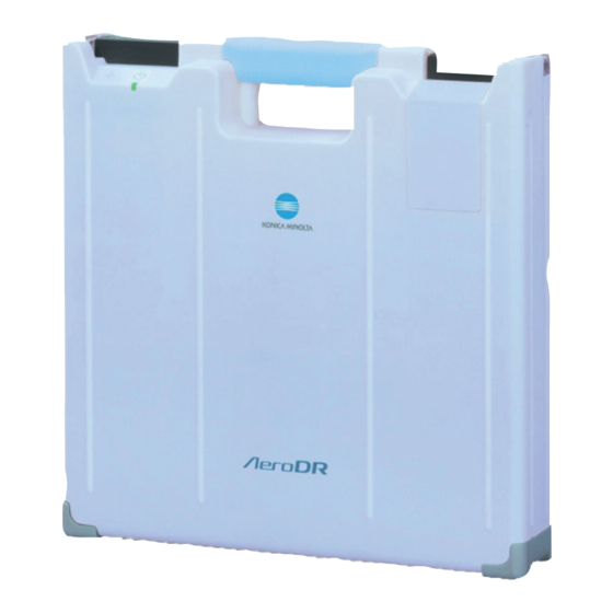
This section describes the functions of AeroDR Portable UF Unit and its system configuration. 2 .1 .1 Functions The AeroDR Portable UF Unit allows X-ray radiography in any facility by combination of AeroDR Detector, image processing controller configuration, and X-ray device. Also, this unit receives an image data sent from the AeroDR Detector by using the built-in AeroDR Access Point and transfers it to the image processing controller . - Page 25 • • • • • • • • • • • • • • • • • • • • • • • • • • • • • • • • • • • • • • • • • • • • • • • • • • • • • • • • • • • • • • • • • • • • • • • • • • • • • • • • • • • • • • • • • • • • • • • • • • • • • • The wired connection may be used in the AeroDR Portable UF Unit and image processing controller by preparing X-ray de- vice side hub .
-
Page 26: Component Names And Functions
2 .2 Component names and functions 2 .2 .1 AeroDR Portable UF Unit The component names and functions of the AeroDR Portable UF Unit are as follows . (3) Holder (4) LAN cable grip cover (5) LAN port (2) Battery stopper... -
Page 27: Aerodr Portable Unit Battery
Number Name Functions Battery connector The connector port to AeroDR Portable UF Unit Indicates the AeroDR Portable Unit Battery recharging status . Reference Charging LED light • For the display patterns and status of the LEDs, see "Chapter 4 Status (LED) Display"... -
Page 28: Charger Kit
Power cable cover This is the cover of the power cable connector . Power cable connector Plugs into the power cable socket of AeroDR Portable UF Unit . Recharger unit Used to recharge the AeroDR Portable Unit Batteries . Power cable... - Page 29 Chapter General Operations This chapter describes general operation methods of the AeroDR Portable UF Unit .
-
Page 30: Startup And Shutdown
. Confirm that the LED (green) is Start each system unit in the following procedure . slowly flashing. Start the AeroDR Portable UF Unit . • Confirm that the AeroDR Portable Unit Battery is mounted . • Turn on the power switch of the AeroDR Por- table UF Unit, and confirm that the Power LED (green) lights . - Page 31 Power switch LED (green) Shut down the image processing control- ler . Shut down the AeroDR Portable UF Unit . • Turn off the power switch of the AeroDR Por- table UF Unit, and confirm that the Power LED LED (green) (green/orange) is turned off .
-
Page 32: Unit
•••••••••••••••••••••••••••••••••••••••••••••••••• •• • HINT •••••••••••••••••••••••••••••••••• • •• • While the AeroDR Portable UF Unit is being recharged inside the X-ray device, disconnect the power cable from the receptacle and store it in the storage com- partment of the X-ray device . -
Page 33: Chapter 1 3 .2 .2 Exposure
• ••• •• •• •• ••• •• •• •• •• ••• •• •• •• ••• • • • • the Ethernet cable that is connected to the AeroDR • After the AeroDR Portable UF Unit is turned ON, it Detector registration side hub from the X-ray device may require approximately 1 minute for wireless con- side hub . - Page 34 Reference •••••••••••••••••••••••••••••••••• • •• ler, refer to the "Operation Manual" of the image pro- • For the shutdown of the AeroDR Portable UF Unit, re- cessing controller . fer to "3 .1 Startup and shutdown" . • • •• • • •• • • •• •••••••••••••••••••••••••••••••••• •••••••...
- Page 35 3 .2 Operations on the AeroDR Portable UF Unit Plug the power cables in a receptacle to 3 .2 .4 Mounting or dismounting recharge the AeroDR Portable UF Unit and the AeroDR Portable Unit Battery the image processing controller .
- Page 36 3 .2 Operations on the AeroDR Portable UF Unit Make sure that the AeroDR Portable Unit Pull out the AeroDR Portable Unit Battery Battery is locked and secured by the bat- from the battery slot . tery stopper . Battery stopper z Dismounting Slide the battery stopper to release it .
-
Page 37: Operating The Mount Kit
3 .2 Operations on the AeroDR Portable UF Unit z When the AeroDR Portable CS7 12P Mount Kit 3 .2 .5 Operating the mount kit Sh1 is used • If the image processing controller is locked to the column of a X-ray device, pull the handle to... - Page 38 Image processing controller IMPORTANT ••••••••••••••••••••••••••••••••••••• • Turn off the AeroDR Portable UF Unit when transport- ing the X-ray device because it may affect the sur- roundings with radio transmissions . • • •• • • •• • • •• •••••••••••••••••••••••••••••••••• •••••••...
- Page 39 3 .2 Operations on the AeroDR Portable UF Unit z When the AeroDR Portable CS7_17P Mount When taking radiography Kit Si1D is used z When the AeroDR Portable CS7_17P Mount Image processing Kit Si1D is used controller • When taking radiography, pull the mount kit all the way toward you, and fasten it while it is locked into place .
- Page 40 3 .2 Operations on the AeroDR Portable UF Unit z When the AeroDR Portable CS7 12P Mount Kit Sh1 is used Position to install a security lock Image processing controller Mount kit Consumables • Refer to each device’s manual for information about periodic replacement parts and consumables for the image processing controller, etc .
- Page 41 . But, there is nothing wrong with the equipment . •• • •• •• • •• •• ••••••••••••••••••••••••••••••••••••••••• 3 .3 .1 Recharging Recharge the AeroDR Portable UF Unit in the follow- Power ing procedure . cable Turn OFF the AeroDR Portable UF Unit...
- Page 42 To recharge the battery with the AeroDR Portable UF Unit inserted in the X-ray device, follow the steps be- low . Turn OFF the AeroDR Portable UF Unit Power cable and confirm that the Power LED (green/ orange) is turned OFF .
- Page 43 10% voltage level, the buzzer sounds . At the same time, the orange Power LED starts to blink on the AeroDR Portable UF Unit . • When you remove the AeroDR Portable Unit Batteries, the green battery level LED goes out .
- Page 44 3 .4 Operations on the AeroDR Portable UF Detector Charger Kit By using the AeroDR Portable UF Detector Charger IMPORTANT •••••••••••••••••••••••••••••••••• • •• Kit, you can recharge the AeroDR Detector while mov- • Check that the AeroDR Portable Unit Battery on the ing the Unit .
- Page 45 •• • •• •• • •• •• ••••••••••••••••••••••••••••••••••••••••• Charger Kit side . • Plug the power cable connector into the power cable socket of the AeroDR Portable UF Unit . HINT ••••••••••••••••••••••••••••••••••••• • Plug the power cable of the AeroDR Portable •...
- Page 46 3 .4 Operations on the AeroDR Portable UF Detector Charger Kit 3 .4 .4 Storing Panel Charge Cable When fixing the Panel Charge Cable to the X-ray de- vice using the Rubber Magnet and Connector Plate, store the Panel Charge Cable by following the proce- dure below .
-
Page 47: Chapter 2 Status (Led) Display
Chapter Status (LED) Display This chapter describes the LED display patterns and the status of the respective devices . -
Page 48: Aerodr Portable Uf Unit
Status of the respective devices can be confirmed with LEDs. Check the status of the respective devices, referring to the "LED display pattern" . LED display pattern Notation Display pattern Flashing 4 .1 .1 AeroDR Portable UF Unit Power LED light Power LED (green/orange) Display pattern Status Shutdown condition The level of AeroDR Portable Unit Batteries is lower than 10% (and the orange LED blinks) . -
Page 49: Troubleshooting
Chapter Troubleshooting This chapter describes problems that may occur and error codes that may be displayed, and how to resolve each of them . -
Page 50: Various Problems And Countermeasures
5 .1 Various problems and countermeasures If the following problems occur in the AeroDR Portable UF Unit, consult the respective references for countermea- sures . IMPORTANT • • • • • • • • • • • • • • • • • • • • • • • • • • • • • • • • • • • • • • • • • • • • • • • • • • • • • • • • • • • • • • • • • • • • • • • • • • • • • • • • • • • • • • • • • • • • • • • • • • • • •... -
Page 51: Charger Kit
Error description Corrective actions Part of the wired connection connector of the AeroDR Detector is deformed . Contact Konica Minolta technical representa- tives . The spring connector of the Panel Charge The Panel Charge Cable can- Cable is deformed . -
Page 53: Maintenance
Chapter Maintenance This chapter describes the items that require periodic maintenance . -
Page 54: Maintenance And Inspection Items
Power LED, LAN port, power cable socket and Panel Charge port . • Do not clean with sharp or hard metal objects . If you cannot remove stains, contact Konica Minolta techni- cal representatives . •••••••••••••••••••••••••••••••••••••••••••••••••• • ••... -
Page 55: Periodical Replacement Parts
6 .1 Maintenance and inspection items 6 .1 .3 Periodical replacement parts The approximate battery replacement cycle is follows . Estimated Replacement parts replacement AeroDR Portable Unit Battery 2 years IMPORTANT ••••••••••••••••••••••••••••••••••••• • The replacement cycle depends on the frequency of battery operation and conditions . -
Page 57: Specifications
Chapter Specifications This chapter describes the specifications of each system device. -
Page 58: Specifications
7 .1 Specifications 7 .1 .1 AeroDR Portable UF Unit Item Description Product name AeroDR Portable UF Unit Normal operation: DC24 .6±0 .3V 2 .0A direct current Power requirements During charging: AC 100/110/115/120/200/220/230/240 VAC ±10%, single phase, 50/60 Hz 386(W)×72(D)×386(H)mm... -
Page 59: Aerodr Portable Unit Battery
7.1 Specifications 7 .1 .2 AeroDR Portable Unit Battery Item Description Product name AeroDR Portable Unit Battery Power consumption Approx . 60VA 75(W)×320(D)×23(H)mm External dimensions 320mm 23mm 75mm Weight 760 g Battery type Lithium-ion batteries • To use the AeroDR Portable UF Detector Charger Kit, two AeroDR Portable Unit Batteries are required . 7 .1 .3 AeroDR Portable UF Detector Charger Kit Item Description... -
Page 60: General Aerodr Portable Uf Unit
7.1 Specifications 7 .1 .4 General AeroDR Portable UF Unit Item Description Temperature Humidity 35 to 80% RH 30°C 80%RH When operating 10 to 30°C (ensure no water con- densation) 35 %RH 10°C Temperature Humidity 20 to 90% RH When not oper- 40°C... - Page 64 A4T4BA01EN08 2015-09-04 (SE)