Table of Contents
Advertisement
Quick Links
KA01135D/06/EN/04.14
71265299
Products
Brief Operating Instructions
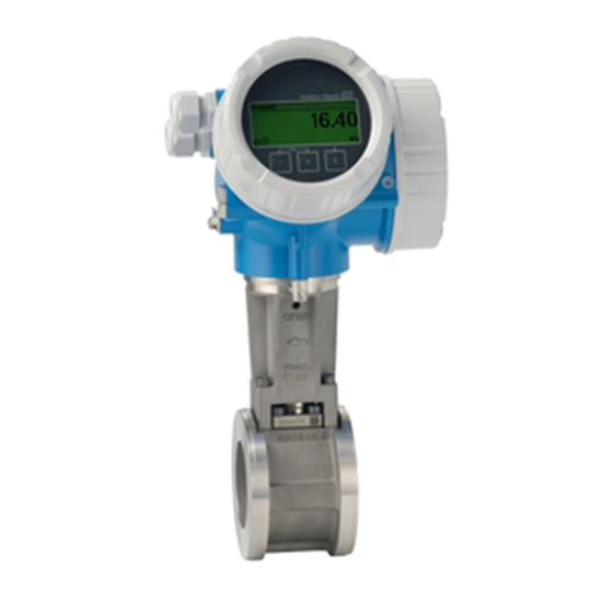
Proline Prowirl D 200
Vortex flowmeter
These Instructions are Brief Operating Instructions; they are
not a substitute for the Operating Instructions pertaining to
the device.
Detailed information about the device can be found in the
Operating Instructions and the other documentation:
• On the CD-ROM supplied (is not included in the delivery for
all device versions).
• Available for all device versions via:
– Internet:
www.endress.com/deviceviewer
– Smart phone/tablet: Endress+Hauser Operations App
Solutions
Services
Advertisement
Table of Contents

Related Manuals for Endress+Hauser Proline Prowirl D 200


Summary of Contents for Endress+Hauser Proline Prowirl D 200
- Page 1 Detailed information about the device can be found in the Operating Instructions and the other documentation: • On the CD-ROM supplied (is not included in the delivery for all device versions). • Available for all device versions via: – Internet: www.endress.com/deviceviewer – Smart phone/tablet: Endress+Hauser Operations App...
- Page 2 Proline Prowirl D 200 Order code 00X00-XXXX0XX0XXX Ser. No.: X000X000000 TAG No.: XXX000 Serial number www.endress.com/deviceviewer Endress+Hauser Operations App A0023555 Endress+Hauser...
-
Page 3: Table Of Contents
Proline Prowirl D 200 Table of contents Table of contents Document information ............4 Symbols used . -
Page 4: Document Information
Document information Proline Prowirl D 200 Document information Symbols used 1.1.1 Safety symbols Symbol Meaning DANGER! DANGER This symbol alerts you to a dangerous situation. Failure to avoid this situation will result in serious or fatal injury. WARNING! This symbol alerts you to a dangerous situation. Failure to avoid this situation can result in WARNING serious or fatal injury. -
Page 5: Basic Safety Instructions
Proline Prowirl D 200 Basic safety instructions 1.1.4 Symbols for certain types of information Symbol Meaning Symbol Meaning Permitted Preferred Procedures, processes or actions that Procedures, processes or actions that are permitted. are preferred. Forbidden Procedures, processes or actions that Indicates additional information. -
Page 6: Designated Use
Verification for borderline cases: ‣ For special fluids and fluids for cleaning, Endress+Hauser is glad to provide assistance in verifying the corrosion resistance of fluid-wetted materials, but does not accept any warranty or liability as minute changes in the temperature, concentration or level of contamination in the process can alter the corrosion resistance properties. -
Page 7: Operational Safety
It meets general safety standards and legal requirements. It also complies with the EC directives listed in the device-specific EC Declaration of Conformity. Endress+Hauser confirms this by affixing the CE mark to the device. IT security We only provide a warranty if the device is installed and used as described in the Operating Instructions. -
Page 8: Incoming Acceptance And Product Identification
(depends on device version) and documents present? • If one of the conditions is not satisfied, contact your Endress+Hauser Sales Center. • Depending on the device version, the CD-ROM might not be part of the delivery! The Technical Documentation is available via the Internet or via the Endress+Hauser Operations App. -
Page 9: Product Identification
• Enter serial numbers from nameplates in W@M Device Viewer (www.endress.com/deviceviewer): All information about the measuring device is displayed. • Enter the serial number from the nameplates into the Endress+Hauser Operations App or scan the 2-D matrix code (QR code) on the nameplate with the Endress+Hauser Operations App: all the information for the measuring device is displayed. -
Page 10: Transporting The Product
Storage and transport Proline Prowirl D 200 Transporting the product Transport the measuring device to the measuring point in the original packaging. A0015604 Do not remove protective covers or caps installed on process connections. They prevent mechanical damage to the sealing surfaces and contamination in the measuring tube. - Page 11 Proline Prowirl D 200 Storage and transport 5.2.3 Transporting with a fork lift If transporting in wood crates, the floor structure enables the crates to be lifted lengthwise or at both sides using a forklift. Endress+Hauser...
-
Page 12: Installation
Installation Proline Prowirl D 200 Installation Installation conditions 6.1.1 Mounting position Mounting location A0015543 Orientation The direction of the arrow on the sensor nameplate helps you to install the sensor according to the flow direction. Vortex meters require a fully developed flow profile as a prerequisite for correct volume flow measurement. - Page 13 Proline Prowirl D 200 Installation Orientation Compact version Remote version 4) 5) C Horizontal orientation, transmitter head down A0015590 D Horizontal orientation, transmitter head at side A0015592 In the case of liquids, there should be upward flow in vertical pipes to avoid partial pipe filling (Fig. A). Disruption in flow measurement! In the case of vertical orientation and downward flowing liquid, the pipe always needs to be completely filled to ensure correct liquid flow measurement.
- Page 14 Installation Proline Prowirl D 200 Rotating the electronics housing and the display The electronics housing can be rotated continuously by 360 °° on the housing support. The display unit can be rotated in 45 ° stages. This means you can read the display comfortably from all directions.
- Page 15 If the required inlet runs cannot be observed, it is possible to install a specially designed flow conditioner which can be ordered from Endress+Hauser. The flow conditioner is fitted between two pipe flanges and centered by the mounting bolts. Generally this reduces the inlet run needed to 10 ×...
- Page 16 Installation Proline Prowirl D 200 3...5 x DN 4...8 x DN A0019205 Pressure transmitter Temperature transmitter 6.1.2 Requirements from environment and process Ambient temperature range Compact version Measuring device Non-Ex: –40 to +80 °C (–40 to +176 °F) Ex i: –40 to +70 °C (–40 to +158 °F)
- Page 17 Proline Prowirl D 200 Installation ‣ If operating outdoors: Avoid direct sunlight, particularly in warm climatic regions. Temperature tables Observe the interdependencies between the permitted ambient and fluid temperatures when operating the device in hazardous areas. For detailed information on the temperature tables, see the separate document entitled "Safety Instructions"...
- Page 18 Installation Proline Prowirl D 200 Vibrations The correct operation of the measuring system is not affected by plant vibrations up to 1 g, 10 to 500 Hz. Therefore no special measures are needed to secure the sensors. Endress+Hauser...
- Page 19 Proline Prowirl D 200 Installation 6.1.3 Special mounting instructions Installation for delta heat measurements Order code for "Sensor version", option 3 "Mass flow (integrated temperature measurement)" The second temperature measurement is taken using a separate temperature sensor. The measuring device reads in this value via a communication interface.
-
Page 20: Mounting The Measuring Device
Installation Proline Prowirl D 200 Mounting the measuring device 6.2.1 Required tools For transmitter • For turning the transmitter housing: Open-ended wrench8 mm • For opening the securing clamps: Allen key3 mm For sensor For flanges and other process connections: Corresponding mounting tools 6.2.2... - Page 21 Proline Prowirl D 200 Installation A mounting kit comprises: • Tie rods • Seals • Nuts • Washers A0019875 4 Mounting kit for wafer version Nut, washer, tie rod Seal Centering ring (is supplied with the measuring device) A mounting kit can be ordered separately (see the "Accessories" section ).
- Page 22 Installation Proline Prowirl D 200 Wall mounting 19 (0.6) 80 (3.15) A0019864 5 Engineering unit mm (in) Endress+Hauser...
- Page 23 Proline Prowirl D 200 Installation Post mounting 20…70 ( 0.79 to 2.75) SW 13 A0019862 6 Engineering unit mm (in) Post retainer kit for post mounting 6.2.5 Turning the transmitter housing To provide easier access to the connection compartment or display module, the transmitter housing can be turned.
-
Page 24: Post-Installation Check
Installation Proline Prowirl D 200 6.2.6 Turning the display module The display module can be turned to optimize display readability and operability. 3 mm A0013905 Post-installation check Is the device undamaged (visual inspection)? Does the measuring device conform to the measuring point specifications? For example: •... -
Page 25: Electrical Connection
Proline Prowirl D 200 Electrical connection Electrical connection The measuring device does not have an internal circuit breaker. For this reason, assign the measuring device a switch or power-circuit breaker so that the power supply line can be easily disconnected from the mains. - Page 26 Electrical connection Proline Prowirl D 200 For further information on planning and installing PROFIBUS PA networks see: • Operating Instructions "PROFIBUS DP/PA: Guidelines for planning and commissioning" (BA00034S) • PNO Directive 2.092 "PROFIBUS PA User and Installation Guideline" • IEC 61158-2 (MBP)
- Page 27 Proline Prowirl D 200 Electrical connection 7.1.3 Terminal assignment Transmitter Connection versions A0020738 A0020739 Maximum number of terminals Maximum number of terminals for order code for Terminals 1 to 6: "Accessory mounted", option NA "Overvoltage Without integrated overvoltage protection protection"...
- Page 28 Electrical connection Proline Prowirl D 200 Remote version In the case of the remote version, the sensor and transmitter are mounted separately from one another and connected by a connecting cable. The sensor is connected via the connection housing while the transmitter is connected via the connection compartment of the wall holder unit.
- Page 29 Proline Prowirl D 200 Electrical connection 7.1.4 Pin assignment, device plug PROFIBUS PA Device plug for signal transmission (device side) Assignment Coding Plug/socket PROFIBUS PA + Plug Grounding PROFIBUS PA – Not assigned A0019021 FOUNDATION Fieldbus Device plug for signal transmission (device side)
- Page 30 Electrical connection Proline Prowirl D 200 potential equalization, therefore, cable shielding of fieldbus systems should only be grounded on one side, for example at the fieldbus supply unit or at safety barriers. A0019004 Controller (e.g. PLC) Segment coupler PROFIBUS DP/PA or Power Conditioner (FOUNDATION Fieldbus)
- Page 31 Proline Prowirl D 200 Electrical connection 7.1.6 Requirements for the supply unit Supply voltage Transmitter Increase in minimum terminal voltage Increase in minimum Local operation terminal voltage Order code for "Display; Operation", option C: + DC 1 V Local operation SD02 Order code for "Display;...
- Page 32 Electrical connection Proline Prowirl D 200 R [ ] U [V] A0020417 8 Load for a compact version without local operation Operating range 1.1 For order code for "Output", option A "4-20 mA HART"/option B "4-20 mA HART, pulse/frequency/ switch output"...
-
Page 33: Connecting The Measuring Device
Proline Prowirl D 200 Electrical connection Connecting the measuring device NOTICE Limitation of electrical safety due to incorrect connection! ‣ For use in potentially explosive atmospheres, observe the information in the device-specific Ex documentation. 7.2.1 Connecting the remote version WARNING Risk of damaging the electronic components! ‣... - Page 34 Electrical connection Proline Prowirl D 200 Connecting the sensor connection housing 3 mm A0020410 A0020411 Wire the connecting cable: Terminal 1 = brown cable Terminal 2 = white cable Terminal 3 = yellow cable Terminal 4 = green cable Connect the cable shield via the cable strain relief.
- Page 35 Proline Prowirl D 200 Electrical connection Connection to the wall holder of the transmitter Connecting the transmitter via plug A0020412 Connecting the transmitter via terminals 3 mm A0020404 Endress+Hauser...
- Page 36 Electrical connection Proline Prowirl D 200 TX 10 8 mm A0020405 ~15° A0020406 Endress+Hauser...
- Page 37 Proline Prowirl D 200 Electrical connection A0020407 A0020409 Wire the connecting cable: Terminal 1 = brown cable Terminal 2 = white cable Terminal 3 = yellow cable Terminal 4 = green cable Connect the cable shield via the cable strain relief.
- Page 38 Electrical connection Proline Prowirl D 200 Connection via terminals 3 mm 20 mm 10 (0.4) mm (in) A0013836 ‣ Connect the cable in accordance with the terminal assignment . For HART communication: when connecting the cable shielding to the ground terminal, observe the grounding concept of the facility.
-
Page 39: Hardware Settings
Proline Prowirl D 200 Electrical connection Hardware settings 7.3.1 Setting the device address PROFIBUS PA The address must always be configured for a PROFIBUS DP/PA device. The valid address range is between 1 and 126. In a PROFIBUS DP/PA network, each address can only be assigned once. -
Page 40: Ensuring The Degree Of Protection
Electrical connection Proline Prowirl D 200 2 + 8 = 10 A0015902 10 Example of hardware addressing; switch 8 is set to the "OFF" position; switches 1 to 7 define the address. Software addressing Set switch 8 to "ON". -
Page 41: Post-Connection Check
Proline Prowirl D 200 Electrical connection A0013960 Insert dummy plugs into unused cable entries. Post-connection check Are cables or the device undamaged (visual inspection)? Do the cables comply with the requirements (→ 25)? Do the cables have adequate strain relief? ... -
Page 42: Operation Options
Operation options Proline Prowirl D 200 Operation options Structure and function of the operating menu 8.1.1 Structure of the operating menu Operating menu for operators and maintenances Language Operation task-oriented Setup Diagnostics Operating menu for experts Expert function-oriented A0014058-EN 12 Schematic structure of the operating menu 8.1.2... -
Page 43: Access To The Operating Menu Via The Local Display
Proline Prowirl D 200 Operation options Access to the operating menu via the local display X X X X X X 19.184 mA 12.5 X X X X X X Language à 20.50 English Deutsch Español Français User ABC_ DEFG... - Page 44 Operation options Proline Prowirl D 200 8.2.1 Operational display Status area The following symbols appear in the status area of the operational display at the top right: • Status signals – F: Failure – C: Function check – S: Out of specification –...
- Page 45 Proline Prowirl D 200 Operation options Display area • Icons for menus – : Operation – : Setup – : Diagnostics – : Expert • : Submenus • : Wizards • : Parameters within a wizard • : Parameter locked 8.2.3...
- Page 46 Operation options Proline Prowirl D 200 8.2.4 Operating elements Keys and meaning Minus key • In a menu, submenu: Moves the selection bar upwards in a choose list. • With a wizard: Confirms the parameter value and goes to the previous parameter.
-
Page 47: Access To The Operating Menu Via The Operating Tool
Proline Prowirl D 200 System integration 8.2.5 Further information For further information on the following topics, see the Operating Instructions for the device • Calling up help text • User roles and related access authorization • Disabling write protection via access code •... - Page 48 System integration Proline Prowirl D 200 Defined order of modules The modules are permanently assigned to the slots, i.e. when configuring the modules, the order and the arrangement of the modules must be respected. Slot Module Function block 1…4 Analog Input block 1 to 4...
- Page 49 Proline Prowirl D 200 System integration Factory setting Function block Factory setting Function block Factory setting AI 1 Volume flow AI 3 Corrected volume flow AI 2 Mass flow AI 4 Density TOTAL module Transmit a totalizer value from the measuring device to the PROFIBUS master (Class 1).
- Page 50 System integration Proline Prowirl D 200 SETTOT_MODETOT_TOTAL module The module combination consists of the SETTOT, MODETOT and TOTAL functions: • SETTOT: Control the totalizers via the PROFIBUS master. • MODETOT: Configure the totalizers via the PROFIBUS master. • TOTAL: Transmit the totalizer value along with the status to the PROFIBUS master.
-
Page 51: Commissioning
Proline Prowirl D 200 Commissioning Selection: device function The device function can be specified using the CHANNEL parameter. CHANNEL Device function Factory setting: state (meaning) Switch output state • 0 (device function not active) Low flow cut off • 1 (device function active) -
Page 52: Switching On The Measuring Device
Commissioning Proline Prowirl D 200 10.2 Switching on the measuring device After a successful function check, switch on the measuring device. After a successful startup, the local display switches automatically from the startup display to the operational display. If nothing appears on the local display or a diagnostic message is displayed, refer to the Operating Instructions for the device 10.3... -
Page 53: Protecting Settings From Unauthorized Access
Proline Prowirl D 200 Diagnostic information The wizards available in the particular device can vary on account of the device version (e.g. communication method). Wizard Meaning Current output 1 Set output 1 Current output 2 Set output 2 Pulse/frequency/switch output... - Page 54 Diagnostic information Proline Prowirl D 200 X X X X X X X X X X X X X X 20.50 S801 Supply voltage Menu Diagnostic list Diagnostics 1 S801 Supply voltage Diagnostics 2 Diagnostics 3 Supply voltage (ID:203) S801 0d00h02m25s...
- Page 56 www.addresses.endress.com...