Endress+Hauser Dosimass Operating Instructions Manual
Coriolis mass flow measuring system for filling applications
Hide thumbs
Also See for Dosimass:
- Operating instructions manual (92 pages) ,
- Technical information (40 pages) ,
- Operating instructions manual (84 pages)

Related Manuals for Endress+Hauser Dosimass


Summary of Contents for Endress+Hauser Dosimass
- Page 1 Operating Instructions Dosimass Coriolis mass flow measuring system For filling applications BA00097D/06/EN/14.12 71195407 Valid as of version 01.01.zz (device software)
-
Page 3: Table Of Contents
Dosimass Table of contents Table of contents Safety instructions ....4 9.13 Disposal ....... . . 32 Designated use . -
Page 4: Safety Instructions
• The device must be operated by persons authorized and trained by the facility's owner-operator. Strict compliance with the instructions in the Operating Instructions is mandatory. • Endress+Hauser is willing to assist in clarifying the chemical resistance properties of parts wetted by special fluids, including fluids used for cleaning. However, small changes in temperature, concentration or the degree of contamination in the process can result in changes of the chemical resistance properties. -
Page 5: Return
The measuring device must be returned if repairs or a factory calibration are required, or if wrong measuring device has been ordered or delivered. According to legal regulations, Endress+Hauser, as an ISO-certified company, is required to follow certain procedures when handling returned products that are in contact with medium.:... -
Page 6: Identification
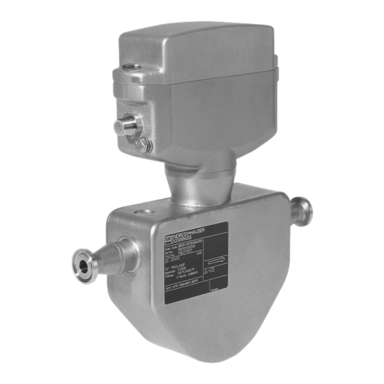
Identification Dosimass Identification Device designation The Dosimass flow measuring system consists of a compact measuring device and is supplied as a mechanical unit. 2.1.1 Nameplate DOSIMASS XXXXX-XXXXXXX Order Code: IP67 / NEMA/Type4X 12345678901 Ser.No.: ABCDEFGHJKLMNP TAG No.: 4.3W 24VDC nominal (20…30VDC) Dn25 / 1”... -
Page 7: Installation
Dosimass Installation Installation Incoming acceptance, transport, storage 3.1.1 Incoming acceptance On receipt of the goods, check the following points: • Check the packaging and the contents for damage. • Check the shipment, make sure nothing is missing and that the scope of supply matches your order. - Page 8 Installation in a down pipe (e.g. for batching applications) Supply tank Sensor Orifice plate, pipe restriction Valve Batching tank Dosimass / DN 8 (3/8") 15 (½") 25 (1") Ø Orifice plate, pipe restriction 6 mm (0.24 in) 10 mm (0.39 in) 14 mm (0.55 in)
- Page 9 " Caution! The measuring tubes of Dosimass are slightly curved. The position of the sensor, therefore, has to be matched to the fluid properties when the sensor is installed horizontally (å 5). A0008609 Fig. 5: Horizontal installation with Dosimass Not suitable for fluids with entrained solids.
- Page 10 Installation Dosimass Fluid temperature " Caution! Hot surface temperatures can arise at the housing of the device if fluid temperatures are > 70 °C (158 °F). In order to ensure that the maximum permissible ambient temperature for the transmitter ...
-
Page 11: Post-Installation Check
Dosimass Installation Post-installation check Perform the following checks after installing the measuring device in the pipe: Device condition and specifications Notes Is the device damaged (visual inspection)? – ä 33 ff. Does the device correspond to specifications at the measuring point, including process temperature and pressure, ambient temperature, measuring range, etc.? -
Page 12: Wiring
Dosimass Wiring Warning! When connecting Ex-certified devices, see the notes and diagrams in the Ex-specific supplement to these Operating Instructions. Please do not hesitate to contact your Endress+Hauser sales office if you have any questions. Connecting the measuring unit Warning! The device may only be connected to SELV, PELV or CLASS 2 circuits. - Page 13 Dosimass Wiring Connection with adapter 8 8pole (power supply, pulse 4.1.2 output, status output) RSE8 A0007237 Wiring diagram with adapter 8 8pole Fig. 7: Socket at device Cable connector Adapter (+), power supply (24 V DC nominal voltage (20 to 30 VDC), 4.3 W) (–), power supply (24 V DC nominal voltage (20 to 30 VDC), 4.3 W)
- Page 14 Wiring Dosimass Connection with adapter 8 5pole (power supply, pulse 4.1.3 output, status output) RSE5 A0007238 Wiring diagram with adapter 8 5pole Fig. 9: Socket at device Cable connector Adapter (+), power supply (24 V DC nominal voltage (20 to 30 VDC), 4.3 W) (–), power supply (24 V DC nominal voltage (20 to 30 VDC), 4.3 W)
- Page 15 Dosimass Wiring Connection with adapter 8 4pole (power supply, pulse 4.1.4 output) RSE4 A0007239 Wiring diagram with adapter 8 4pole Fig. 11: Socket at device Cable connector Adapter (+), power supply (24 V DC nominal voltage (20 to 30 VDC), 4.3 W) (–), power supply (24 V DC nominal voltage (20 to 30 VDC), 4.3 W)
-
Page 16: Potential Equalization
Ground connection The ground connection is established via a cable lug. A0007235 Fig. 13: Dosimass ground connection 4.1.6 Cable specification Every suitable cable with a temperature specification at least 20 °C (68 °F) higher than the ambient temperature in the application. We recommend you use a cable with a temperature specification of +80 °C (+176 F). -
Page 17: Post-Connection Check
Dosimass Wiring Post-connection check Perform the following checks after completing electrical installation of the measuring device: Device condition and specifications Notes Is the device damaged (visual inspection)? – Electrical connection Notes 24 V DC nominal voltage Does the supply voltage match the specifications on the nameplate? -
Page 18: Operation
Configuration 5.1.1 Customer specific configuration via FieldCare The Dosimass flow measuring device is operated via the "FieldCare" operating program. FieldCare is a universal service and configuration software package from Endress+Hauser. Note! You can find more information on FieldCare and how it is operated in the appropriate on-line help. -
Page 19: Structure Of The Function Matrix
Dosimass Operation Structure of the function matrix Function group Function MEASURING VALUES MASS FLOW VOLUME FLOW DENSITY TEMPERATURE ä 41 ä 41 ä 41 ä 41 ä 41 SYSTEM UNITS UNIT MASS FLOW UNIT MASS UNIT VOLUME FLOW UNIT VOLUME UNIT DENSITY ä... - Page 20 Changing certain parameters such as all sensor characteristics, for example, influences numerous functions of the entire measuring system, particularly measuring accuracy. Such parameters normally may not be altered and are thus protected. Please contact Endress+Hauser if you have any questions. Endress+Hauser...
-
Page 21: Commissioning
Calibration takes place under reference operating conditions (ä 35). Consequently, zero point adjustment is generally not necessary for Dosimass! Experience shows that the zero point adjustment is advisable only in special cases: •... - Page 22 Commissioning Dosimass 6.3.1 Preconditions for a zero point adjustment Note the following before you perform a zero point adjustment: • A zero point adjustment can be performed only with fluids that contain no gas or solid contents. • A zero point adjustment is performed with the measuring tubes completely filled and at zero flow (v = 0 m/s (0 ft/s)).
-
Page 23: Maintenance
Accessories Various accessories , which can be ordered separately from Endress+Hauser, are available for the transmitter and sensor. Detailed information on the order code in question can be obtained from your Endress+Hauser service organization. -
Page 24: Troubleshooting
Dosimass Troubleshooting Troubleshooting instructions Fault conditions that arise during operation are immediately identified by Dosimass and signaled and output in different ways: • Via a light-emitting diode (LED) on the electronics (ä 25) • Via the status output (ä 29) •... -
Page 25: Fault Diagnosis Via The Light Emitting Diode (Led)
This kind of fault diagnosis is not possible in Ex-areas since the electronics compartment can only be opened if no voltage is being supplied to the device. A0004753 Fig. 16: Fault diagnosis with Dosimass using light emitting diode (LED) Status of light-emitting diode (LED) Status of measuring system LED lights up green... -
Page 26: System Error Messages (Fieldcare)
In the event of a serious fault, a flowmeter might have to be returned to the manufacturer for repair. The procedures on ä 5 must be carried out before you return the device to Endress+Hauser. Always enclose a duly completed "Declaration of contamination" form. You will find a preprinted form at the back of this manual. -
Page 27: Process Error Messages (Fieldcare)
Check whether the plug of the sensor signal LOWER MEAS. TUBE measuring tube is likely defective. cable is correctly inserted into the TEMPERATURE LIMIT electronics module before contacting your local Endress+Hauser service organization # 382 ä 30. UPPER MEAS. TUBE TEMPERATURE LIMIT # 385... - Page 28 Troubleshooting Dosimass Type No./error message Cause Remedy / spare part # 701 The maximum current value for the In particular with outgassing fluids and/or EXCITING CURRENT measuring tube exciter coils has been increased gas content, the following LIMIT reached, since certain process fluid measures are recommended to increase characteristics are extreme, e.g.
-
Page 29: Process Errors Without Message
Returning devices to Endress+Hauser The procedures on ä 5 must be carried out before you return a flowmeter requiring repair or calibration to Endress+Hauser. Always enclose a duly completed "Declaration of contamination" form with the flowmeter. You will find a preprinted "Declaration of contamination"... -
Page 30: Installing/Removing The Electronics
– Plug for power supply and signal outputs (6) Loosen Phillips screws (7) and remove Electronics module (8). Installation is the reverse of the removal procedure. " Caution! Use only original Endress+Hauser parts. A0004756 Fig. 17: Installing and removing the electronics Hexagonal-headed bolt (AF 10) -
Page 31: Replacing The Device Fuse
Remove the electronics module (ä 30). Replace the fuse (1) with a pincers. Installation is the reverse of the removal procedure. " Caution! Use only original Endress+Hauser parts. A0004757 Fig. 18: Replacing the device fuse on the electronics. Device fuse... -
Page 32: Software History
Troubleshooting Dosimass 9.11 Software history Date Software version Software modifications Documentation 08.2012 1.01.XX No changes to software 71…/14.12 01.2011 71128087/13.11 03.2007 1.01.00 New functionalities: 71039226/04.07 – Selection of a measuring mode for the pulse output – New limit switch for the status output with the... -
Page 33: Technical Data
Dosimass Technical data Technical data 10.1 Technical data at a glance 10.1.1 Application The measuring device is for measuring the mass flow and volume flow of liquids in sealed piping systems. Fluids with widely differing properties can be measured, for example: •... - Page 34 Technical data Dosimass 10.1.4 Output Output signal Pulse output: Passive, max. 30 V DC/25 mA, pulse value and pulse polarity can be selected, pulse width adjustable (0.05 ms to 1 s). Note! The device may only be connected to SELV, PELV or CLASS 2 circuits.
- Page 35 0.0662 Calculation example: Give that: Dosimass DN 15, flow = 1300 kg/h (47.8 lb/min) Measured error: ±0.3% ± [(zero point stability : measured value) · 100]% o.r. Measured error: ±0.3% ± (0,65 kg/h : 13 00 kg/h) · 100% = ±0.35%...
- Page 36 Technical data Dosimass 10.1.7 Installation ä 7 ff. Installation instructions Inlet and outlet run There are no installation requirements regarding inlet and outlet runs. ä 9 System pressure 10.1.8 Environment Ambient temperature range –20 to +60 °C (–4 to +140 °F) (sensor, transmitter) Install the device at a shady location.
- Page 37 Pressure loss diagram with water Pressure loss (US units) Pressure loss ist dependent on fluid properties nominal diameter. Consult Endress+Hauser for Applicator PC software to determine pressure loss in US units. All important instrument data is contained in the Applicator software programm in order to optimize the design of measuring system.
- Page 38 10.1.11 Operability Display elements Dosimass does not have a display or display elements. Remote operation Operation takes place via the "FieldCare" configuration and service program from Endress+Hauser. This can be used to configure functions and read off measured values. Endress+Hauser...
- Page 39 CE mark The measuring system is in conformity with the statutory requirements of the EC Directives. Endress+Hauser confirms successful testing of the device by affixing to it the CE mark. C-tick mark The measuring system meets the EMC requirements of the "Australian Communications and Media Authority (ACMA)".
- Page 40 Technical data Dosimass 10.1.13 Ordering information The Endress+Hauser service organization can provide detailed ordering information and information on specific order codes on request. 10.1.14 Accessories/spare parts ä 23 10.1.15 Supplementary Documentation ❑Technical Information Dosimass (TI00065D/06/EN) ❑Supplementary documentation on Ex-ratings: ATEX...
-
Page 41: Appendix - Function Description
Appendix - Function description This Appendix provides you with a detailed description of, and information on, the individual device functions of Dosimass. All the device functions can be selected and configured via the "FieldCare" configuration program from Endress+Hauser ä 18. -
Page 42: Function Group System Units
Appendix - Function description Dosimass 11.2 Function group SYSTEM UNITS Function description Function group SYSTEM UNITS UNIT MASS FLOW Use this function to select the unit for displaying the mass flow (mass/time). Options: Metric: gram g/s; g/min; g/h; g/day kilogram ... - Page 43 Dosimass Appendix - Function description Function description Function group SYSTEM UNITS UNIT VOLUME Use this function to select the unit for the volume. Options: Metric cm ; l; ml; l; hl; Ml ; dm US cc; af; ft ;...
-
Page 44: Function Group Pulse Output
Appendix - Function description Dosimass 11.3 Function group PULSE OUTPUT Function description Function group PULSE OUTPUT ASSIGN PULSE Use this function to assign a measured variable to the pulse output. Options: MASS FLOW VOLUME FLOW Factory setting: MASS FLOW PULSE VALUE Use this function to define the flow at which a pulse is triggered. - Page 45 Dosimass Appendix - Function description Function description Function group PULSE OUTPUT PULSE WIDTH Use this function to enter the pulse width of the output pulses. User input: 0.05 to 1000 ms Factory setting: 0.05 ms The pulses are always output with the pulse width (B) entered in this function. The intervals (P) between the individual pulses are automatically configured.
-
Page 46: Function Group Status Output
Appendix - Function description Dosimass Function description Function group PULSE OUTPUT FAILSAFE MODE For reasons of safety it is advisable to ensure that the pulse output assumes a predefined state in the event of a fault. Use this function to define this state. -
Page 47: Function Group Communication
Dosimass Appendix - Function description Function description Function group STATUS OUTPUT ACTUAL STATUS Use this function to display the current status of the status output. DISPLAY: NON CONDUCTIVE CONDUCTIVE 11.5 Function group COMMUNICATION Function description Function group COMMUNICATION TAG NAME Use this function to assign a tag name to the measuring device. - Page 48 Appendix - Function description Dosimass Function description Function group PROCESS PARAMETER PRESSURE SHOCK Severe liquid movement can occur briefly in the pipeline when a valve is closed. This is SUPPRESSION recorded by the measuring system. For this reason, the device is equipped with pressure shock suppression (= time-based signal suppression) which can eliminate "faults"...
- Page 49 Dosimass Appendix - Function description Function description Function group PROCESS PARAMETER PRESSURE SHOCK Use this function to specify in what situations pressure shock suppression is activated. SUPPRESSION MODE Options: STANDARD Pressure shock suppression is only activated if the flow enters low flow cutoff from a positive flow direction.
-
Page 50: Function Group System Parameter
Appendix - Function description Dosimass 11.7 Function group SYSTEM PARAMETER Function description Function group SYSTEM PARAMETER INSTALLATION Use this function to reverse the sign of the measured variable, if necessary. DIRECTION SENSOR Note! Ascertain the actual direction of fluid flow with reference to the direction indicated by the arrow on the sensor nameplate. -
Page 51: Function Group Sensor Parameter
Dosimass Appendix - Function description 11.8 Function group SENSOR PARAMETER Function description SENSOR PARAMETER function group All sensor data, including calibration factor, zero point, nominal diameter, etc. are set at the factory. All the sensor's parameter settings are saved on the DAT memory chip. -
Page 52: Function Group Supervision
Appendix - Function description Dosimass 11.9 Function group SUPERVISION Function description Function group SUPERVISION ACTUAL SYSTEM Use this function to display the current system status. CONDITION Display: "SYSTEM OK" or the fault/notice message with the highest priority. PREVIOUS SYSTEM Use this function to display the 16 most recent fault and notice messages. -
Page 53: 11.10 Function Group Simulation
Dosimass Appendix - Function description 11.10 Function group SIMULATION Function description Function group SIMULATION SIMULATION Use this function to simulate a measured variable to check that the pulse output behaves MEASURAND correctly, for example. During this time, the words "SIMULATION MEASURAND"... -
Page 54: Index
Dosimass Index Index EPD RESPONSE TIME ......49 EPD VALUE LOW ......49 Accessories. - Page 55 Dosimass Index Measuring range ....... . 33 Measuring system ....... 33 Reference operating conditions .
- Page 56 Dosimass Index Weight ........38...
- Page 57 Erklärung zur Kontamination und Reinigung Please reference the Return Authorization Number (RA#), obtained from Endress+Hauser, on all paperwork and mark the RA# clearly on the outside of the box. If this procedure is not followed, it may result in the refusal of the package at our facility.
- Page 58 www.endress.com/worldwide BA00097D/06/EN/14.12 71195407 FM+SGML 10.0 ProMoDo...