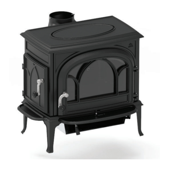
Jøtul F 500 ECO UKCA Installation And Operating Instructions Manual
Hide thumbs
Also See for F 500 ECO UKCA:
- Installation and operating instructions manual (68 pages) ,
- Installation and operating instructions manual (36 pages)
Table of Contents
Advertisement
Quick Links
UKCA information
UK - Installation and operating instructions
The manuals which are enclosed with the product must be kept throughout the product's entire service life.
Les manuels fournis avec le produit doivent être conservés pendant toute la durée de vie du produit.
Los manuales suministrados con este producto deben guardarse durante todo el ciclo de vida del producto. I
manuali inclusi con il prodotto vanno conservati per l'intera durata di vita del prodotto.
Jøtul F 500 ECO UKCA
2
3
Advertisement
Table of Contents

Related Manuals for Jøtul F 500 ECO UKCA


Summary of Contents for Jøtul F 500 ECO UKCA
-
Page 1: Dimensions, Distances See Fi G
Jøtul F 500 ECO UKCA UKCA information UK - Installation and operating instructions The manuals which are enclosed with the product must be kept throughout the product’s entire service life. Les manuels fournis avec le produit doivent être conservés pendant toute la durée de vie du produit. - Page 2 Attention! Use this approval label when the stoves has been installed (only for UK). Cut off the bottom part and replace the label already attached with this one. It is important that the lot + pin number is viewable. Note: An approved CO monitor should be installed in the same room as the appliance.
-
Page 3: Table Of Contents
ENGLISH UK - Installation and 1.0 Relationship to the operating instructions authorities Installation of a fi replace must be in accordance with local codes and regulations in each country. Table of contents All local regulations, including those which refer to national and European standards, must be observed when installing 1.0 Relationship to the authorities the product. -
Page 4: Safety
ENGLISH 3.0 Safety Requirements for protection of infl ammable fl oors in front of the fi replace NB! To guarantee optimal performance and safety, Jøtul The front plate must comply with national laws and regulations. recommends that its stoves are fi tted by a qualifi ed Please note that there is a side door on the product. - Page 5 ENGLISH...
-
Page 6: Installation
ENGLISH 4.0 Installation 4.2 Installation • Before installing the fi replace, check it carefully for any Fig. 3a Assemble the side door handle - parts signs of damage. • The product is heavy! Ask someone to help you when positioning and installing it. •... - Page 7 ENGLISH Fig. 5 Mount the ash lip front Fig. 7a Switch from top outlet to rear outlet 1. The ash lip is mounted on the front of the stove. Fig. 6 Mount ash lip side 1. Unscrew the 2 screws with nuts on the back. 2.
- Page 8 ENGLISH Assembly of the fl ue pipe Air supply The product is assembled for a top outlet as standard. The amount of combustion air for Jøtul’s products is approximately 20-40 m /h. The outside air connection may be fi tted directly to the Jøtul F 500 ECO through: Fig.
- Page 9 ENGLISH 4.4 Location of approval label Fig. 9c Through the fl oor and basement Fig. 11 Approval label 1. The approval label is located at the bottom of the stove. Fig. 9d indirecitly through an outside wall 4.5 Chimney and fl ue pipe •...
-
Page 10: Daily Use
ENGLISH 4.6 Performance check 5.2 Valve adjustment Once the product has been assembled, always check the control handles. These should move easily and work in a Fig. 13 satisfactory manner. Fig. 12 The Jøtul F 500 ECO is equipped with the following operating options: Pulled to the right : Open (used during ignition). - Page 11 ENGLISH 5.6 Wood consumption Fig. 14 Jøtul F 500 ECO has a nominal heat output of ca. 8,8 kW. Use of wood, with nominal heat emission: Approx. 1,97 kg/h. The size of the logs should be: Kindling: Length: 30-55 cm Diameter: 5 cm Amount per fi...
- Page 12 ENGLISH 5.8 Removing the ashes Fog and mist can have a signifi cant impact on the chimney draught and it might be necessary to use other combustion air • Only remove ashes when the fi replace is cold. settings to ensure good performance. •...
-
Page 13: Maintenance
ENGLISH 6.0 Maintenance 7.0 Service Any unauthorised modifi cations to the product are prohibited! 6.1 Cleaning the glass Only original spare parts may be used! The product is equipped with an air wash for the glass. Air is Fig. 17 sucked in through the air vent on the top of the product and down along the inside of the glass. - Page 14 ENGLISH Fig. 18b Removing of baffl e plates Fig. 19b Replacing the exhaust defl ector 2. The baffl e plates are now loose and can be edged out of the stove. NB: Right plate fi rst, then left. When refi tting, follow the same procedure in reverse order 2.
- Page 15 ENGLISH 7.3 Replacing the burn plates Fig. 20c Fig. 20a Replacing the rear burn plate 2. Edge the rear burn plate out of the stove. 3. When refi tting, follow the same procedure in reverse order. (fi rst see fi g. 21 (insulation mats)) 1.
-
Page 16: Operational Problems - Troubleshooting
ENGLISH 7.4 Replacing the ash grate Fig. 22 Replacing the side burn plate (Right) Fig. 24 replacing the ash grate 1. Loosen the screw and the washer that holds the side burn 1. Tilt up the ash grate that loosely sits in the bottom plate of the plate (A) and the insulation mat (B) in place. -
Page 17: Optional Equipment
ENGLISH 9.0 Optional equipment 2. The guarantee does not cover: 2.1. Damage to consumables such as burn plates, fi re grates, fl ue baffl es, gaskets and similar as these deteriorate over time due to normal wear and tear. 9.1 Heat shield rear 2.2. - Page 18 Jøtul arbeider kontinuerlig for om mulig å forbedre sine produkter, og vi forbeholder oss retten til å endre spesifi kasjoner, farger og utstyr uten nærmere kunngjøring. Jøtul AS arbejder kontinuerlig med om mulig at forbedre sine produkter, og vi forbeholder os ret til at endre specifi...