Siemens SINAMICS G120D Operating Instructions Manual
Distributed converter, control units with encoder evaluation
Hide thumbs
Also See for SINAMICS G120D:
- List manual (910 pages) ,
- Operating instructions manual (398 pages) ,
- Original instructions manual (382 pages)
Table of Contents
Advertisement
Quick Links
Advertisement
Table of Contents

Related Manuals for Siemens SINAMICS G120D


Summary of Contents for Siemens SINAMICS G120D
- Page 3 ___________________ Converter with control units CU240D-2 Changes in this manual Fundamental safety ___________________ instructions ___________________ SINAMICS Introduction ___________________ Description SINAMICS G120D Converter with control units ___________________ CU240D-2 Installation ___________________ Commissioning Operating Instructions ___________________ Advanced commissioning ___________________ Backing up data and series...
- Page 4 Note the following: WARNING Siemens products may only be used for the applications described in the catalog and in the relevant technical documentation. If products and components from other manufacturers are used, these must be recommended or approved by Siemens. Proper transport, storage, installation, assembly, commissioning, operation and maintenance are required to ensure that the products operate safely and without any problems.
-
Page 5: Changes In This Manual
Changes in this manual Notable changes since the 04/2015 edition of the manual New functions in firmware V4.7 SP6 ● Evaluation of a PT1000 motor temperature sensor Motor temperature monitoring using a temperature sensor (Page 179) ● New p4621 parameter for disabling PTC short-circuit monitoring Motor temperature monitoring using a temperature sensor (Page 179) ●... - Page 6 Changes in this manual Converter with control units CU240D-2 Operating Instructions, 07/2016, FW V4.7 SP6, A5E34262100B AD...
-
Page 7: Table Of Contents
Introduction ............................21 About the Manual ........................21 Guide through the manual ...................... 22 Description ............................25 SINAMICS G120D CU240D-2 Inverter ................... 25 Commissioning tools ....................... 27 Motor series that are supported ....................29 Installation ............................31 Mechanical Installation......................31 Electrical Installation ....................... - Page 8 Table of contents 4.3.2.3 Integrating inverters into PROFINET ..................74 4.3.2.4 Configuring communication to the control ................74 4.3.2.5 Installing GSDML ........................76 4.3.3 PROFIBUS ..........................77 4.3.3.1 What do you need for communication via PROFIBUS? ............77 4.3.3.2 Integrating the inverter in PROFIBUS ..................77 4.3.3.3 Configuring the communication using SIMATIC S7 control ...........
- Page 9 Table of contents 6.3.2 Analog input as setpoint source .................... 138 6.3.3 Specifying the setpoint via the fieldbus................. 139 6.3.4 Motorized potentiometer as setpoint source ................. 140 6.3.5 Fixed speed as setpoint source .................... 142 Setpoint calculation ....................... 145 6.4.1 Overview of setpoint processing ...................
- Page 10 Table of contents 6.7.7.2 Further information ....................... 216 Safe Torque Off (STO) safety function ................217 6.8.1 Function description ......................217 6.8.2 Prerequisite for STO use ..................... 219 6.8.3 Commissioning STO ......................220 6.8.3.1 Commissioning tools ......................220 6.8.3.2 Safety functions password ....................220 6.8.3.3 Configuring safety functions ....................
- Page 11 Technical data ............................ 309 10.1 Performance ratings Control Unit ..................309 10.2 Performance ratings Power Module ..................311 10.3 SINAMICS G120D specifications ..................312 10.4 Data regarding the power loss in partial load operation ............312 10.5 Ambient operating conditions ....................313 10.6 Current derating - depending on the installation altitude ............
- Page 12 Table of contents Converter with control units CU240D-2 Operating Instructions, 07/2016, FW V4.7 SP6, A5E34262100B AD...
-
Page 13: Fundamental Safety Instructions
Fundamental safety instructions General safety instructions DANGER Danger to life due to live parts and other energy sources Death or serious injury can result when live parts are touched. • Only work on electrical devices when you are qualified for this job. •... - Page 14 Fundamental safety instructions 1.1 General safety instructions WARNING Danger to life when live parts are touched on damaged devices Improper handling of devices can cause damage. For damaged devices, hazardous voltages can be present at the enclosure or at exposed components;...
- Page 15 Fundamental safety instructions 1.1 General safety instructions WARNING Danger to life due to fire spreading if housing is inadequate Fire and smoke development can cause severe personal injury or material damage. • Install devices without a protective housing in a metal control cabinet (or protect the device by another equivalent measure) in such a way that contact with fire is prevented.
- Page 16 Fundamental safety instructions 1.1 General safety instructions WARNING Danger of an accident occurring due to missing or illegible warning labels Missing or illegible warning labels can result in accidents involving death or serious injury. • Check that the warning labels are complete based on the documentation. •...
-
Page 17: Safety Instructions For Electromagnetic Fields (Emf)
Fundamental safety instructions 1.2 Safety instructions for electromagnetic fields (EMF) WARNING Danger to life or malfunctions of the machine as a result of incorrect or changed parameterization As a result of incorrect or changed parameterization, machines can malfunction, which in turn can lead to injuries or death. -
Page 18: Handling Electrostatic Sensitive Devices (Esd)
Siemens recommends strongly that you regularly check for product updates. For the secure operation of Siemens products and solutions, it is necessary to take suitable preventive action (e.g. cell protection concept) and integrate each component into a holistic, state-of-the-art industrial security concept. - Page 19 • Keep the software up to date. You will find relevant information and newsletters at this address (http://support.automation.siemens.com). • Incorporate the automation and drive components into a holistic, state-of-the-art industrial security concept for the installation or machine.
-
Page 20: Residual Risks Of Power Drive Systems
Fundamental safety instructions 1.5 Residual risks of power drive systems Residual risks of power drive systems When assessing the machine- or system-related risk in accordance with the respective local regulations (e.g., EC Machinery Directive), the machine manufacturer or system installer must take into account the following residual risks emanating from the control and drive components of a drive system: 1. -
Page 21: Introduction
Introduction About the Manual Who requires the operating instructions and what for? These operating instructions primarily address fitters, commissioning engineers and machine operators. The operating instructions describe the devices and device components and enable the target groups being addressed to install, connect-up, set, and commission the converters safely and in the correct manner. -
Page 22: Guide Through The Manual
Introduction 2.2 Guide through the manual Guide through the manual Section In this section you will find answers to the following questions: How is the inverter marked? • Description Which components make up the inverter? (Page 25) • Which motors can be fed from the inverter? •... - Page 23 Introduction 2.2 Guide through the manual Section In this section you will find answers to the following questions: What is the inverter technical data? • Technical data (Page 309) What are the new functions of the current firmware? Appendix (Page 321) • What are the most important inverter parameters? •...
- Page 24 Introduction 2.2 Guide through the manual Converter with control units CU240D-2 Operating Instructions, 07/2016, FW V4.7 SP6, A5E34262100B AD...
-
Page 25: Description
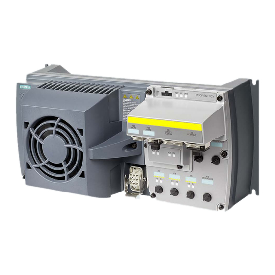
SINAMICS G120D CU240D-2 Inverter Overview The SINAMICS G120D is a converter for controlling the speed of three-phase motors. The converter consists of two parts, the Control Unit (CU) and the Power Module (PM). Table 3- 1... - Page 26 Description 3.1 SINAMICS G120D CU240D-2 Inverter Table 3- 2 PM250D Power Modules Frame Rated output Rated output Article number size power current based on High Overload (HO) 0.75 kW 2.2 A 6SL3525-0PE17-5AA1 1.5 kW 4.1 A 6SL3525-0PE21-5AA1 3.0 kW 7.7 A 6SL3525-0PE23-0AA1 4.0 kW...
-
Page 27: Commissioning Tools
Description 3.2 Commissioning tools Commissioning tools Image 3-1 Commissioning tools - PC or IOP Handheld Kit Converter with control units CU240D-2 Operating Instructions, 07/2016, FW V4.7 SP6, A5E34262100B AD... - Page 28 STARTER and Startdrive download: ● STARTER (http://support.automation.siemens.com/WW/view/en/10804985/133200) ● Startdrive (http://support.automation.siemens.com/WW/view/en/68034568) Help regarding operation: ● STARTER videos (http://www.automation.siemens.com/mcms/mc-drives/en/low-voltage- inverter/sinamics-g120/videos/Pages/videos.aspx) ● Startdrive tutorial (http://support.automation.siemens.com/WW/view/en/73598459) Memory cards Table 3- 3 Memory cards to back up inverter settings Scope of delivery Article number Memory card without firmware 6SL3054-4AG00-2AA0 Memory card with firmware V4.5...
-
Page 29: Motor Series That Are Supported
Description 3.3 Motor series that are supported Motor series that are supported Supported motors Table 3- 4 Motor series suitable for the inverter SIMOTICS GP, SIMOTICS SD IEC motors SIMOTICS M main motors Standard 1LG6, 1LA7, 1LA9, 1LE1 and 1PC1 1PH8 induction motors induction motors SIMOTICS S 1FK7 encoderless permanent-field... - Page 30 A multi-motor drive, i.e. simultaneously operating several motors connected to one inverter, is permissible for standard induction motors in installations according to IEC. Additional information is provided in the Internet: Multi-motor drive (http://support.automation.siemens.com/WW/view/en/84049346) For installations in compliance with UL, multi-motor drive operation is not permissible. Converter with control units CU240D-2...
-
Page 31: Installation
Installation Mechanical Installation Fitting the Control Unit to the Power Module The inverter is delivered as two separate components - the Power Module (PM) and the Control Unit (CU). The CU must be fitted to the PM prior to any further commissioning taking place. - Page 32 The inverter has an identical drill pattern for all frame sizes. The drill pattern, depth and tightening torques are shown in the diagram below. Image 4-2 SINAMICS G120D drill pattern Converter with control units CU240D-2 Operating Instructions, 07/2016, FW V4.7 SP6, A5E34262100B AD...
- Page 33 Installation 4.1 Mechanical Installation Mounting orientation Mount the converter on a table or on a wall. The minimum clearance distances are as follows: ● Side-by-side - no clearance distance is required ● Above and below the inverter 150 mm (5.9 inches). Image 4-3 Mounting orientation: correct (✓), impermissible (X), permissible with restrictions (!) Restrictions due to vertical mounting...
-
Page 34: Electrical Installation
Installation 4.2 Electrical Installation Electrical Installation 4.2.1 Overview of the interfaces Intefaces of the converter ① ⑧ Digital inputs 0 … 5 with status LED HTL Encoder connection ② ⑨ Fieldbus IN and OUT (PROFINET or PROFIBUS) Analog inputs 0 and 1 ③... -
Page 35: Permissible Line Supplies
Installation 4.2 Electrical Installation NOTICE Material damage from inappropriate supply system V > 1% Operating the converter on an inappropriate supply system can cause damage to the converter and other loads. • Only operate the converter on supply systems with V ≤... -
Page 36: Protective Conductor
Installation 4.2 Electrical Installation 4.2.3 Protective conductor WARNING Danger to life caused by high leakage currents for an interrupted protective conductor The drive components conduct a high leakage current via the protective conductor. Touching conductive parts when the protective conductor is interrupted can result in death or serious injury. - Page 37 Installation 4.2 Electrical Installation ① ④ The minimum cross-section of the protective conductor … depends on the cross- section of the line or motor feeder cable: ● Line or motor feeder cable ≤ 16 mm ⇒ Minimum cross-section of the protective conductor = cross-section of the line or motor feeder cable ●...
-
Page 38: Grounding Converter And Motor
Installation 4.2 Electrical Installation 4.2.4 Grounding converter and motor Grounding the converter ● Ground the converter via the PE connection in the mains supply connector. ● Ground the connectors as shown in the diagram below. Image 4-5 Grounding the line supply and motor connectors •... - Page 39 Installation 4.2 Electrical Installation EMC cable glands Where cable glands are used within the installation of the system, it is recommended that EMC glands are used. The cable gland provides protection to the IP68 standard when fitted correctly. Image 4-6 Example of a Blueglobe EMC cable gland Table 4- 1 Brass-nickel plated EMC cable gland with metric thread as per EN50262.
-
Page 40: Basic Emc Rules
Installation 4.2 Electrical Installation 4.2.5 Basic EMC Rules Measures to limit Electromagnetic Interference (EMI) Listed below are the necessary measures that must be taken to ensure the correct installation of the Inverter within a system, which will minimize the effect of EMI. Cables ●... -
Page 41: Connections And Interference Suppression
Installation 4.2 Electrical Installation 4.2.6 Connections and interference suppression All connections should be made so that they are permanent. Screwed connections on painted or anodized metal components must be made either by means of special contact washers, which penetrate the isolating surface and establish a metallically conductive contact, or by removing the isolating surface on the contact points. - Page 42 Grounding and high-frequency equipotential bonding measures in the drive system and in the plant You find further information on the rules for EMC compliant installation on the Internet: EMC design guidelines (http://support.automation.siemens.com/WW/view/en/60612658/0/en) Converter with control units CU240D-2 Operating Instructions, 07/2016, FW V4.7 SP6, A5E34262100B AD...
-
Page 43: Branch Circuit Protection Of Individual Inverters
Installation 4.2 Electrical Installation 4.2.8 Branch circuit protection of individual inverters When you install a dedicated 400 V branch for each inverter, then you must individually fuse/protect each branch. Image 4-8 Power supply to inverters through their own dedicated 400 V branch Branch circuit protection according to the IEC standard Table 4- 2 Branch circuit protection according to the IEC standard... - Page 44 DIVQ Type E combination motor controller (designation according to the UL standard - is NKJH available as SIEMENS circuit breaker) Table 4- 4 Branch circuit protection with non-semiconductor fuses of Classes J, T, CC, G or CF (UL Category JDDZ)
- Page 45 Installation 4.2 Electrical Installation Rated Power Module Frame Article No. UL cat. Max. rated current Short circuit current power size of the circuit rating SCCR breaker 4 kW 6SL3525-0PE24-0AA1 FSC 3RV1742… DIVQ 35 A 65 kA, 480Y/277 V AC LGG… or CED6… DIVQ 35 A 65 kA, 480 V 3 AC...
-
Page 46: Branch Circuit Protection Of Multiple Inverters
Installation 4.2 Electrical Installation 4.2.9 Branch circuit protection of multiple inverters For installations with more than one inverter, the inverters are normally powered from a 400- V power bus with a T distributor. Image 4-9 Power supply to an inverter group via a shared 400-V branch circuit Calculation of the branch circuit protection according to IEC and UL standards Calculation of the branch circuit protection: ●... - Page 47 Fuses of any manufacturer with faster tripping characteristic than class RK5, e.g. JDDZ class J, T, CC, G, or CF SIEMENS circuit breaker DIVQ Intrinsically safe SIEMENS circuit breaker NKJH Table 4- 8 Branch circuit protection with non-semiconductor fuses of Classes J, T, CC, G or CF (UL Category Code JDDZ) Max.
-
Page 48: 24-V Power Supply With Multiple Inverters
Installation 4.2 Electrical Installation 4.2.10 24-V power supply with multiple inverters Installation using 24 V bus The following options are available for the 24 V supply of the inverter: 1. A T distributor with integrated power supply unit supplies the 24 V. Advantage: Low installation costs. -
Page 49: Connections And Cables
Installation 4.2 Electrical Installation 4.2.11 Connections and cables Connectors "Switched" and "unswitched" 24 V power supply The unswitched 24 V power supply (1L+) is required for the device to function. The switched 24 V (2L+) supplies the two digital outputs. Switching brings all of the actuators connected to the digital outputs into the no-voltage state. - Page 50 Installation 4.2 Electrical Installation Image 4-11 CU240D-2 PROFIBUS connectors Converter with control units CU240D-2 Operating Instructions, 07/2016, FW V4.7 SP6, A5E34262100B AD...
- Page 51 Installation 4.2 Electrical Installation Image 4-12 CU240D-2 PROFINET connectors Converter with control units CU240D-2 Operating Instructions, 07/2016, FW V4.7 SP6, A5E34262100B AD...
- Page 52 Installation 4.2 Electrical Installation Image 4-13 CU240D-2 PROFINET Push-Pull connectors Converter with control units CU240D-2 Operating Instructions, 07/2016, FW V4.7 SP6, A5E34262100B AD...
- Page 53 Installation 4.2 Electrical Installation Image 4-14 CU240D-2 PROFINET FO connectors Converter with control units CU240D-2 Operating Instructions, 07/2016, FW V4.7 SP6, A5E34262100B AD...
- Page 54 Installation 4.2 Electrical Installation DANGER Danger to life when live parts are touched in the motor terminal box Hazardous voltage can be present on the pins for temperature sensor and motor holding brake. Touching live parts on the motor cable and in the motor terminal box can lead to death due electrical shock.
- Page 55 The detailed specifications for the cables, connectors and tools required to manufacture the necessary cables for the SINAMICS G120D are listed in the following tables. The connections that are detailed in this section relate to the physical connections that exist on the Inverter.
- Page 56 (12 or 10 AWG) 3RK1911-2BE10 5.50 kW … 7.50 kW 6 mm (10 AWG) 3RK1911-2BE30 You find information about motor connectors in the internet: Solution partner (https://www.automation.siemens.com/solutionpartner/partnerfinder/Partner- Finder.aspx?lang=en) Cable lengths Table 4- 15 Maximum cable lengths Cable Screening Max. length...
-
Page 57: Star-Delta Motor Connection
Before you connect the motor, ensure that the motor has the appropriate connection for your application: Motor is connected in the star or delta configuration With SIEMENS motors, you will see a diagram of both connection methods on the inside of the cover of the terminal box: •... -
Page 58: Connecting The Motor Holding Brake
Installation 4.2 Electrical Installation 4.2.13 Connecting the motor holding brake WARNING Danger to life when live parts are touched in the motor terminal box The temperature sensor and motor holding brake connections are at DC link negative potential. Touching these connections can result in death or severe injury. •... -
Page 59: Factory Settings Of The Inputs And Outputs
Installation 4.2 Electrical Installation 4.2.14 Factory settings of the inputs and outputs Factory settings of the inputs and outputs of the control unit CU240D-2 In the factory settings, the fieldbus interface of the inverter is not active. Image 4-17 Factory settings of the control units CU240D-2 Changing the function of the inputs and outputs The function of each color-identified input and output can be set. -
Page 60: Default Settings Of Inputs And Outputs
Installation 4.2 Electrical Installation 4.2.15 Default settings of inputs and outputs Default setting 1: "Conveyor system with 2 fixed frequencies" DO 0: p0730, DO 1: p0731 DI 0: r0722.0, …, DI 5: r0722.5 Fixed speed setpoint 3: p1003, fixed speed setpoint 4: p1004, fixed speed setpoint active: r1024 Speed setpoint (main setpoint): p1070[0] = 1024 DI 4 and DI 5 = high: the inverter adds the two fixed speed setpoints Default setting 2: "Conveyor system with Basic Safety"... - Page 61 Installation 4.2 Electrical Installation Default setting 3: "Conveyor system with 4 fixed frequencies" DO 0: p0730, DO 1: p0731 DI 0: r0722.0, …, DI 5: r0722.5 Fixed speed setpoint 1: p1001, … fixed speed setpoint 4: p1004, fixed speed setpoint active: r1024 Speed setpoint (main setpoint): p1070[0] = 1024 Several of the DI 0, DI 1, DI 4, and DI 5 = high: the inverter adds the corresponding fixed speed set- points.
- Page 62 Installation 4.2 Electrical Installation Default setting 5: "Conveyor system with fieldbus and Basic Safety" DO 0: p0730, DO 1: p0731 DI 4: r0722.4, DI 5: r0722.5 Speed setpoint (main setpoint): p1070[0] = 2050[1] Default setting 6: "Fieldbus with Extended Safety" DO 0: p0730, DO 1: p0731 DI 0: r0722.0, …, DI 5: r0722.5 Speed setpoint (main setpoint): p1070[0] = 2050[1]...
- Page 63 Installation 4.2 Electrical Installation Default setting 7: "Fieldbus with data set switchover" DO 0: p0730, DO 1: p0731 DI 0: r0722.0, …, DI 3: r0722.3 Speed setpoint (main setpoint): p1070[0] = 2050[1] Jog 1 speed setpoint: p1058, factory setting: 150 rpm Jog 2 speed setpoint: p1059, factory setting: -150 rpm Converter with control units CU240D-2 Operating Instructions, 07/2016, FW V4.7 SP6, A5E34262100B AD...
- Page 64 Installation 4.2 Electrical Installation Default setting 8: "MOP with Basic Safety" DO 0: p0730, DO 1: p0731 DI 0: r0722.0, …, DI 5: r0722.5 Motorized potentiometer, setpoint after the ramp-function generator r1050 Speed setpoint (main setpoint): p1070[0] = 1050 Default setting 9: "Standard I/O with MOP" DO 0: p0730, DO 1: p0731 DI 0: r0722.0, …, DI 3: r0722.3 Motorized potentiometer, setpoint after the ramp-function generator r1050...
- Page 65 Installation 4.2 Electrical Installation Default setting 12: "Standard I/O with analog setpoint" DO 0: p0730, DO 1: p0731 DI 0: r0722.0, …, DI 2: r0722.2 AI 0: r0755[0] Speed setpoint (main setpoint): p1070[0] = 755[0] Default setting 13: "Standard I/O with analog setpoint and safety" DO 0: p0730, DO 1: p0731 DI 0: r0722.0, …, DI 5: r0722.5 AI 0: r0755[0]...
- Page 66 Installation 4.2 Electrical Installation Default setting 14: "Process industry with fieldbus" DO 0: p0730, DO 1: p0731 DI 0: r0722.0, …, DI 5: r0722.5 Motorized potentiometer, setpoint after the ramp-function generator r1050 Speed setpoint (main setpoint): p1070[0] = 2050[1], p1070[1] = 1050 Converter with control units CU240D-2 Operating Instructions, 07/2016, FW V4.7 SP6, A5E34262100B AD...
- Page 67 Installation 4.2 Electrical Installation Default setting 24: "Distributed conveyor systems with fieldbus" DO 0: p0730, DO 1: p0731 DI 0: r0722.0, …, DI 5: r0722.5 p2081[0] = r0722.0, …, p2081[5] = r0722.5 p0730 = r2094.0, p0731 = r2094.1 Speed setpoint (main setpoint): p1070[0] = 2050[1] Converter with control units CU240D-2 Operating Instructions, 07/2016, FW V4.7 SP6, A5E34262100B AD...
- Page 68 Installation 4.2 Electrical Installation Default setting 25: "Distributed conveyor systems with fieldbus, safety" DO 0: p0730, DO 1: p0731 DI 0: r0722.0, …, DI 5: r0722.5 p2081[0] = r0722.0, …, p2081[3] = r0722.3 p0730 = r2094.0, p0731 = r2094.1 Speed setpoint (main setpoint): p1070[0] = 2050[1] Converter with control units CU240D-2 Operating Instructions, 07/2016, FW V4.7 SP6, A5E34262100B AD...
-
Page 69: Safety Input
Installation 4.2 Electrical Installation 4.2.16 Safety input Which devices are you allowed to connect? The safety-related input is designed for the following devices: ● Connection of safety sensors, e.g. emergency stop command devices or light curtains. ● Connection of pre-processing devices, e.g. fail-safe control systems and safety relays. Signal state The inverter expects signals with the same state at its safety-related input: ●... - Page 70 Installation 4.2 Electrical Installation Bright and dark test The inverter filters signal changes using bright and dark tests at its safe input using an adjustable software filter. Connecting the safety-related input (Page 338) Converter with control units CU240D-2 Operating Instructions, 07/2016, FW V4.7 SP6, A5E34262100B AD...
-
Page 71: Connecting The Inverter To The Fieldbus
Installation 4.3 Connecting the inverter to the fieldbus Connecting the inverter to the fieldbus 4.3.1 Fieldbus versions of the Control Unit Fieldbus interfaces of the Control Units There are different versions of the Control Units for communication with a higher-level control system: Fieldbus Profiles... -
Page 72: Profinet
Installation 4.3 Connecting the inverter to the fieldbus 4.3.2 PROFINET You can either communicate via Ethernet using the inverter, or integrate the inverter in a PROFINET network. The inverter as Ethernet node Image 4-18 The inverter as Ethernet node The inverter in PROFINET IO operation Image 4-19 The inverter in PROFINET IO operation In PROFINET IO operation, the inverter supports the following functions:... -
Page 73: Connecting The Profinet Interface
● Shared Device for Control Units with fail-safe functions General information about PROFINET You can find general information about PROFINET in the Internet: ● General information about PROFINET: Industrial Communication (http://www.automation.siemens.com/mcms/automation/en/industrial- communications/profinet/Pages/Default.aspx). ● Configuring the functions: PROFINET system description (http://support.automation.siemens.com/WW/view/en/19292127). -
Page 74: What Do You Need For Communication Via Profinet
Installation 4.3 Connecting the inverter to the fieldbus 4.3.2.2 What do you need for communication via PROFINET? Check the communication settings using the following table. If you answer "Yes" to the questions, you have correctly set the communication settings and can control the inverter via the fieldbus. - Page 75 Installation 4.3 Connecting the inverter to the fieldbus Configuring the communication with a non-Siemens control 1. Import the device file (GSDML) of the inverter into the engineering tool for your control system. 2. Configure the communication. Configure communication with STARTER STARTER provides a screen form to set the communication with the control system.
-
Page 76: Installing Gsdml
Set p0804 = 12. The inverter writes the GSDML as zipped file (*.zip) into directory /SIEMENS/SINAMICS/DATA/CFG on the memory card. 2. Unzip the GSDML file to a folder on your computer. 3. Import the GSDML into the configuring tool of your control system. -
Page 77: Profibus
Installation 4.3 Connecting the inverter to the fieldbus 4.3.3 PROFIBUS 4.3.3.1 What do you need for communication via PROFIBUS? Check the communication settings using the following table. If you answer "Yes" to the questions, you have correctly set the communication settings and can control the inverter via the fieldbus. -
Page 78: Installing The Gsd
– or from your inverter. To do this, insert a memory card into the inverter and set p0804 = 12. In this way, you will save the GSD on the memory card as (DPGSD.ZIP) compressed file in the directory /SIEMENS/SINAMICS/DATA/CFG . 2. Unzip the GSDfile in a folder on your computer. - Page 79 Installation 4.3 Connecting the inverter to the fieldbus Procedure To change the bus address, proceed as follows: 1. Set the address using one of the subsequently listed options: – using the address switch – from an operator panel using parameter p0918 –...
- Page 80 Installation 4.3 Connecting the inverter to the fieldbus Converter with control units CU240D-2 Operating Instructions, 07/2016, FW V4.7 SP6, A5E34262100B AD...
-
Page 81: Commissioning
Commissioning Commissioning guidelines Overview 1. Define the requirements to be met by the drive for your application. (Page 82) 2. Restore the factory settings of the inverter if necessary. (Page 101) 3. Check if the factory setting of the inverter is sufficient for your application. -
Page 82: Preparing For Commissioning
Commissioning 5.2 Preparing for commissioning Preparing for commissioning Before starting commissioning, you must know the following data: ● Which motor is connected to the inverter? Note down the Article No. of the motor and the motor’s nameplate data. If available, note down the motor code on the motor’s nameplate. ●... -
Page 83: Inverter Factory Setting
Commissioning 5.2 Preparing for commissioning 5.2.1 Inverter factory setting Motor With its factory settings, the inverter is set up for an induction motor suitable for the power rating of the Power Module. Inverter interfaces The inputs and outputs and the fieldbus interface of the inverter have specific functions when set to the factory settings. - Page 84 Commissioning 5.2 Preparing for commissioning Switching the motor on and off in the jog mode In the case of inverters with a PROFIBUS or PROFINET interface, operation can be switched via digital input DI 3. The motor is either switched on and off via PROFIBUS – or operated in jog mode via its digital inputs.
-
Page 85: Selecting The Control Mode
Commissioning 5.2 Preparing for commissioning 5.2.2 Selecting the control mode Suitable applications and typical control properties U/f control or FCC (flux current con- Vector control without an encod- Vector control with encoder trol) without an encoder Application Horizontal conveyor technology Horizontal conveyor technol- Vertical conveyor technolo- •... -
Page 86: Quick Commissioning With The Iop
Commissioning 5.3 Quick commissioning with the IOP Quick commissioning with the IOP Commissioning a 1FK7 encoderless synchronous motor If you want to operate the inverter using a 1FK7 encoderless synchronous motor, we recommend using the STARTER for commissioning. Basic commissioning wizard The Basic Commissioning wizard detailed below is for Control Units with version 4.4 software or higher. - Page 87 Commissioning 5.3 Quick commissioning with the IOP Select the correct frequency for your Inverter and at- tached motor. The use of the 87 Hz characteristic allows the motor to operate at 1.73 times of its normal speed. At this stage the wizard will begin to ask for the data relating specifically to the attached motor.
- Page 88 Commissioning 5.3 Quick commissioning with the IOP 11. Input the correct Motor Speed from the motor rating plate. This value is given in RPM. 12. Select to run or disable Motor Data Identification func- tion. This function, if active, will not start until the first run command is given to the Inverter.
- Page 89 Commissioning 5.3 Quick commissioning with the IOP 17. Set the Ramp Up time in seconds. This is the time the Inverter/motor system will take from being given the run command, to reaching the selected motor speed. 18. Set the Ramp Down time in seconds. This is the time the Inverter/motor system will take from being given the OFF1 command, for the motor to reach a standstill.
-
Page 90: Quick Commissioning With A Pc
Commissioning 5.4 Quick commissioning with a PC Quick commissioning with a PC The screen forms that are shown in this manual show generally valid examples. The number of setting options available in screen forms depends on the particular inverter type. Requirements To be able to perform quick commissioning using a PC, you need to do the following: 1. -
Page 91: Transfer Inverters Connected Via Usb Into The Project
Commissioning 5.4 Quick commissioning with a PC 5.4.2 Transfer inverters connected via USB into the project Integrating the inverter into the project Procedure Proceed as follows to transfer an inverter connected via USB to your project: 1. Switch on the inverter supply voltage. 2. - Page 92 Commissioning 5.4 Quick commissioning with a PC 6. When the USB interface is appropriately set, then the "Accessible nodes" screen form shows the inverters that can be accessed. Image 5-5 Inverters found in STARTER Image 5-6 Inverters found in Startdrive If you have not correctly set the USB interface, then the following "No additional nodes found"...
- Page 93 Commissioning 5.4 Quick commissioning with a PC Setting the USB interface in STARTER Procedure Proceed as follows to set the USB interface in STARTER: 1. Set the "Access point" to "DEVICE (STARTER, Scout)" and the "PG/PC interface" to "S7USB". 2. Press the "Update" button. You have set the USB interface.
-
Page 94: Go Online And Start The Configuration Wizards
Commissioning 5.4 Quick commissioning with a PC 5.4.3 Go online and start the configuration wizards Procedure with STARTER Proceed as follows to start the quick commissioning of the inverter: 1. Select your project and go online: 2. In the following screen form, select the inverter with which you wish to go online. -
Page 95: Carrying Out Quick Commissioning
Commissioning 5.4 Quick commissioning with a PC 5.4.4 Carrying out quick commissioning Procedure Proceed as follows to carry out quick commissioning: Select the control mode. Selecting the control mode (Page 85) Select the I/O configuration to preassign the inverter interfaces. Factory settings of the inputs and outputs (Page 59) Default settings of inputs and outputs (Page 60) Set the applicable motor standard and the inverter supply voltage. - Page 96 Commissioning 5.4 Quick commissioning with a PC Motor identification: • [1]: Recommended setting for closed-loop speed control. After an ON command, the inverter identifies the motor data – and with a new ON command, optimizes the speed controller. • [2]: After an ON command, the inverter identifies the motor data at standstill.
-
Page 97: Adapting The Encoder Data
Commissioning 5.4 Quick commissioning with a PC 5.4.5 Adapting the encoder data Preconditions ● You have selected an encoder type that does not precisely match your encoder, because it is not included in the list of default encoder types. ● You have completely configured the drive. Procedure with STARTER Proceed as follows to adapt the encoder data: 1. -
Page 98: Identifying Motor Data
Commissioning 5.4 Quick commissioning with a PC Procedure with Startdrive Proceed as follows to adapt the encoder data: 1. Select the "Motor encoder" screen form. 2. Click the "Encoder data" button. 3. You have access to the following settings in the "Encoder data" screen form: –... - Page 99 Commissioning 5.4 Quick commissioning with a PC Preconditions ● You selected a method of motor data identification during quick commissioning, e.g. measurement of the motor data while the motor is stationary. When quick commissioning is complete, the inverter issues alarm A07991. ●...
- Page 100 Commissioning 5.4 Quick commissioning with a PC Procedure with Startdrive To initiate motor data identification and optimize the motor control, proceed as follows: 1. Open the control panel. 2. Assume master control for the inverter. 3. Set the "Drive enables" 4.
-
Page 101: Restoring The Factory Setting
Commissioning 5.5 Restoring the factory setting Restoring the factory setting 5.5.1 Restoring the factory setting There are cases where something goes wrong when commissioning a drive system e.g.: ● The line voltage was interrupted during commissioning and you were not able to complete commissioning. -
Page 102: Resetting The Safety Functions To The Factory Setting
Commissioning 5.5 Restoring the factory setting 5.5.2 Resetting the safety functions to the factory setting Procedure with STARTER To reset the safety function settings to the factory setting without changing the standard settings, proceed as follows: 1. Go online. 2. Open the screen form of the safety functions. 3. - Page 103 Commissioning 5.5 Restoring the factory setting Procedure with Startdrive To reset the safety function settings to the factory setting without changing the standard settings, proceed as follows: 1. Go online. 2. Select "Commissioning". 3. Select "Backing up/reset". 4. Select "Safety parameters are reset". 5.
- Page 104 Commissioning 5.5 Restoring the factory setting Procedure with an operator panel Proceed as follows to restore the inverter safety functions to the factory settings: 1. p0010 = 30Set Activate reset settings. 2. p9761 = … Enter the password for the safety functions 3.
-
Page 105: Restore The Settings To The Factory Settings (Without Safety Functions)
Commissioning 5.5 Restoring the factory setting 5.5.3 Restore the settings to the factory settings (without safety functions) Restoring the inverter to the factory setting Procedure with STARTER Proceed as follows to reset the inverter to factory settings: 1. Go online 2. - Page 106 Commissioning 5.5 Restoring the factory setting Converter with control units CU240D-2 Operating Instructions, 07/2016, FW V4.7 SP6, A5E34262100B AD...
-
Page 107: Advanced Commissioning
Advanced commissioning Overview of the converter functions The inverter control controls all other functions of the inverter. The inverter control also defines how the inverter responds to external control signals. Inverter control (Page 109) The commands from the higher-level control are sent to the inverter via digital inputs or the fieldbus. - Page 108 Advanced commissioning 6.1 Overview of the converter functions The protection and monitoring functions avoid overloads and operating states that could damage the motor, inverter and driven load. The motor temperature monitoring, for example, is set here. Protection functions (Page 176) The application-specific functions allow you to control a motor holding brake or implement a higher-level pressure or temperature control using the technology controller, for example.
-
Page 109: Inverter Control
Advanced commissioning 6.2 Inverter control Inverter control 6.2.1 Switching the motor on and off After switching the supply voltage on, the converter normally goes into the "ready to start" state. In this state, the converter waits for the command to switch-on the motor: •... - Page 110 Advanced commissioning 6.2 Inverter control The abbreviations S1 … S5b to identify the converter states are defined in the PROFIdrive profile. Converter Explanation status In this state, the converter does not respond to the ON command. The converter goes into this state under the following conditions: ON was active when switching on the converter.
-
Page 111: Adapt Inputs And Outputs
Advanced commissioning 6.2 Inverter control 6.2.2 Adapt inputs and outputs This chapter describes how you adapt the function of individual digital and analog inputs and outputs of the inverter. Image 6-2 Internal interconnection of the inputs and outputs Converter with control units CU240D-2 Operating Instructions, 07/2016, FW V4.7 SP6, A5E34262100B AD... -
Page 112: Digital Inputs
Advanced commissioning 6.2 Inverter control 6.2.2.1 Digital inputs Changing the function of a digital input Interconnect the status parameter of the digital input with a binector input of your choice. Binector inputs are marked with "BI" in the parame- ter list of the List Manual. Table 6- 1 Binector inputs (BI) of the inverter (selection) Significance... -
Page 113: Fail-Safe Digital Input
Advanced commissioning 6.2 Inverter control Advanced settings You can debounce the digital input signal using parameter p0724. For more information, see the parameter list and the function block diagrams 2210 ff of the List Manual. Analog inputs as digital inputs When required, you can use the analog inputs as additional digital inputs. -
Page 114: Digital Outputs
Advanced commissioning 6.2 Inverter control 6.2.2.3 Digital outputs Changing the function of a digital output Interconnect the digital output with a binector output of your choice. Binector outputs are marked with "BO" in the parameter list of the List Manual. Table 6- 2 Binector outputs of the inverter (selection) Deactivating digital output... -
Page 115: Analog Inputs
Advanced commissioning 6.2 Inverter control 6.2.2.4 Analog inputs Overview Changing the function of the analog input 1. Define the analog input type using parameter p0756 to voltage input 0 V … 10 V. 2. Specify the function of the analog input by interconnecting parameter p0755 with a connector input CI of your choice. - Page 116 Advanced commissioning 6.2 Inverter control Table 6- 3 Parameters for the scaling characteristic and wire break monitoring Parameter Description p0757 x-coordinate of 1st characteristic point [V] p0758 y coordinate of the 1st characteristic point [% of p200x] p200x are the parameters of the reference variables, e.g. p2000 is the reference speed.
- Page 117 Advanced commissioning 6.2 Inverter control Specify deadband Small signals of a few millivolts are often corrupted by interference in the cable. To be able to enter a setpoint of exactly 0 V via an analog input, you must specify a deadband. Image 6-4 Deadband of the analog input p0764[0]...
-
Page 118: Running The Motor In Jog Mode (Jog Function)
Advanced commissioning 6.2 Inverter control 6.2.3 Running the motor in jog mode (JOG function) The "Jog" function is typically used to slowly move a machine part, e.g. a conveyor belt. With the "Jog" function, you switch the motor on and off using a digital input. When the motor is switched on, it accelerates to the jogging setpoint. - Page 119 Advanced commissioning 6.2 Inverter control Jog settings Parameter Description p1058 Jogging 1 speed setpoint (factory setting 150 rpm) p1059 Jogging 2 speed setpoint (factory setting -150 rpm) p1082 Maximum speed (factory setting 1500 rpm) p1110 Inhibit negative direction =0: Negative direction of rotation is enabled =1: Negative direction of rotation is inhibited p1111 Inhibit positive direction...
-
Page 120: Control Via Profibus And Profinet With The Profidrive Profile
Advanced commissioning 6.2 Inverter control 6.2.4 Control via PROFIBUS and PROFINET with the PROFIdrive profile The send and receive telegrams of the inverter for the cyclic communication are structured as follows: Image 6-6 Telegrams for cyclic communication Converter with control units CU240D-2 Operating Instructions, 07/2016, FW V4.7 SP6, A5E34262100B AD... - Page 121 Advanced commissioning 6.2 Inverter control Table 6- 5 Explanation of the abbreviations Abbreviation Explanation Abbreviation Explanation Control word MIST_GLATT Actual smoothed torque Status word PIST_GLATT Actual smoothed active power NSOLL_A Speed setpoint M_LIM Torque limit value NIST_A Speed actual value FAULT_CODE Fault number NIST_A_GLATT...
- Page 122 Advanced commissioning 6.2 Inverter control Image 6-8 Interconnection of the receive words The telegrams use - with the exception of telegram 999 (free interconnection) - the word-by- word transfer of send and receive data (r2050/p2051). If you require an individual telegram for your application (e.g. for transferring double words), you can adjust one of the predefined telegrams via parameters p0922 and p2079.
-
Page 123: Control And Status Word 1
Advanced commissioning 6.2 Inverter control 6.2.4.1 Control and status word 1 Control word 1 (STW1) Significance Explanation Signal inter- connection Telegram 20 All other tele- in the in- grams verter 0 = OFF1 The motor brakes with the ramp-down time p0840[0] = p1121 of the ramp-function generator. - Page 124 Advanced commissioning 6.2 Inverter control Significance Explanation Signal inter- connection Telegram 20 All other tele- in the in- grams verter 1 = MOP up Increase the setpoint saved in the motorized p1035[0] = potentiometer. r2090.13 1 = MOP down Reduce the setpoint saved in the motorized p1036[0] = potentiometer.
-
Page 125: Control And Status Word 3
Advanced commissioning 6.2 Inverter control Significance Comments Signal inter- connection Telegram 20 All other tele- in the in- grams verter 0 = Alarm, motor overtemperature -- p2080[13] = r2135.14 1 = Motor rotates clockwise Internal inverter actual value > 0 p2080[14] = r2197.3 0 = Motor rotates counterclock-... - Page 126 Advanced commissioning 6.2 Inverter control Status word 3 (ZSW3) Significance Description Signal intercon- nection in the inverter 1 = DC braking active p2051[3] = r0053 1 = |n_act | > p1226 Absolute current speed > stationary state detection 1 = |n_act | > p1080 Absolute actual speed >...
-
Page 127: Data Structure Of The Parameter Channel
Advanced commissioning 6.2 Inverter control 6.2.4.3 Data structure of the parameter channel Structure of the parameter channel The parameter channel consists of four words. 1. and 2nd word transfer the parameter number and index as well as the type of job (read or write) The 3rd and 4th word contains the parameter contents. - Page 128 Advanced commissioning 6.2 Inverter control Table 6- 7 Response identifiers, inverter → control Response iden- Description tifier No response Transfer parameter value (word) Transfer parameter value (double word) Transfer descriptive element Transfer parameter value (field, word) Transfer parameter value (field, double word) Transfer number of field elements Inverter cannot process the request.
- Page 129 Advanced commissioning 6.2 Inverter control Description 86 hex Write access only for commissioning (p0010 = 15) (operating status of the inverter pre- vents a parameter change) 87 hex Know-how protection active, access locked C8 hex Change request below the currently valid limit (change request to a value that lies within the "absolute"...
-
Page 130: Examples Of The Parameter Channel
Advanced commissioning 6.2 Inverter control Parameter contents Parameter contents can be parameter values or connectors. Table 6- 9 Parameter values in the parameter channel PWE, 3rd word PWE, 4th word Bit 15 … 0 Bit 15 … 8 Bit 7 … 0 8-bit value 16-bit value 32-bit value... - Page 131 Advanced commissioning 6.2 Inverter control Write request: Change restart mode (p1210) The restart mode is inhibited in the factory setting (p1210 = 0). In order to activate the automatic restart with "acknowledge all faults and restart for an ON command", p1210 must be set to 26: ●...
-
Page 132: Extend Telegrams And Change Signal Interconnection
Standard telegram 20, PZD-2/6 350: SIEMENS telegram 350, PZD-4/4 352: SIEMENS telegram 352, PZD-6/6 353: SIEMENS telegram 353, PZD-2/2, PKW-4/4 354: SIEMENS telegram 354, PZD-6/6, PKW-4/4 r2050[0…11] PROFIdrive PZD receive word Connector output to interconnect the PZD (setpoints) in the word format received from the PROFIdrive controller. - Page 133 Advanced commissioning 6.2 Inverter control Freely selecting the signal interconnection of the telegram The signals in the telegram can be freely interconnected. Procedure Proceed as follows to change the signal interconnection of a telegram: 1. Using STARTER or an operator panel, set parameter p0922 = 999. 2.
-
Page 134: Slave-To-Slave Communication
Further information about acyclic communication is provided in the Fieldbus function manual. Overview of the manuals (Page 347) "Reading and writing parameters" application example Further information is provided in the Internet: Application examples (https://support.industry.siemens.com/cs/ww/en/ps/13217/ae) Converter with control units CU240D-2 Operating Instructions, 07/2016, FW V4.7 SP6, A5E34262100B AD... -
Page 135: Switching Over The Inverter Control (Command Data Set)
Advanced commissioning 6.2 Inverter control 6.2.5 Switching over the inverter control (command data set) In some applications, it must be possible to switch over the master control for operating the inverter. Example: The motor is to be operable either from a central control via the fieldbus or via the local digital inputs of the inverter. - Page 136 Advanced commissioning 6.2 Inverter control An overview of all the parameters that belong to the command data sets is provided in the List Manual. Note The converter requires approx. 4 ms to switch over the command data set. Advanced settings To change the number of command data sets in STARTER, you must open your STARTER project offline.
-
Page 137: Setpoints
Advanced commissioning 6.3 Setpoints Setpoints 6.3.1 Overview The inverter receives its main setpoint from the setpoint source. The main setpoint generally specifies the motor speed. Image 6-14 Setpoint sources for the inverter You have the following options when selecting the source of the main setpoint: ●... -
Page 138: Analog Input As Setpoint Source
Advanced commissioning 6.3 Setpoints 6.3.2 Analog input as setpoint source Interconnecting an analog input If you have selected a pre-assignment without a function of the analog input, then you must interconnect the parameter of the main setpoint with an analog input. Image 6-15 Example: Analog input 0 as setpoint source Table 6- 11... -
Page 139: Specifying The Setpoint Via The Fieldbus
Advanced commissioning 6.3 Setpoints 6.3.3 Specifying the setpoint via the fieldbus Interconnecting the fieldbus with the main setpoint Image 6-16 Fieldbus as setpoint source Most standard telegrams receive the speed setpoint as a second process data PZD2. Table 6- 12 Setting the fieldbus as setpoint source Parameter Remark... -
Page 140: Motorized Potentiometer As Setpoint Source
Advanced commissioning 6.3 Setpoints 6.3.4 Motorized potentiometer as setpoint source The "Motorized potentiometer" function emulates an electromechanical potentiometer. The output value of the motorized potentiometer can be set with the "higher" and "lower" control signals. Interconnecting the motorized potentiometer (MOP) with the setpoint source Image 6-17 Motorized potentiometer as setpoint source Image 6-18... - Page 141 Advanced commissioning 6.3 Setpoints Table 6- 14 Extended setup of motorized potentiometer Parameter Description p1030 MOP configuration (factory setting: 00110 bin) Storage active = 0: After the motor has been switched on, the setpoint = p1040 = 1: After the motor has switched off, the inverter saves the setpoint. After the motor has switched on, the setpoint = the stored value Automatic mode, ramp-function generator active (1-signal via BI: p1041) = 0: Ramp-up/ramp-down time = 0...
-
Page 142: Fixed Speed As Setpoint Source
Advanced commissioning 6.3 Setpoints 6.3.5 Fixed speed as setpoint source In many applications after switching on the motor, all that is needed is to run the motor at a constant speed or to switch between different speeds. Example: After it has been switched on, a conveyor belt only runs with two different velocities. - Page 143 Advanced commissioning 6.3 Setpoints 2. Binary selection: You set 16 different fixed setpoints. You precisely select one of these 16 fixed setpoints by a combination of four selection bits. Image 6-21 Simplified function diagram for binary selection of the setpoints Additional information about binary selection can be found in function diagram 3010 in the List Manual.
- Page 144 Advanced commissioning 6.3 Setpoints Example: Select two fixed setpoints directly The motor should operate at different speeds as follows: ● The signal on digital input 0 switches the motor on and accelerates it to 300 rpm. ● The signal at digital input 1 accelerates the motor to 2000 rpm. ●...
-
Page 145: Setpoint Calculation
Advanced commissioning 6.4 Setpoint calculation Setpoint calculation 6.4.1 Overview of setpoint processing The setpoint can be modified as follows using the setpoint processing: ● Invert setpoint to reverse the motor direction of rotation (reversing). ● Inhibit positive or negative direction of rotation, e.g. for conveyor belts, pumps or fans. ●... -
Page 146: Invert Setpoint
Advanced commissioning 6.4 Setpoint calculation 6.4.2 Invert setpoint The inverter provides an option to invert the setpoint sign using a bit. As an example, the setpoint inversion is shown through a digital input. In order to invert the setpoint through the digital input DI 1, connect the parameter p1113 with a binary signal, e.g. -
Page 147: Inhibit Direction Of Rotation
Advanced commissioning 6.4 Setpoint calculation 6.4.3 Inhibit direction of rotation In the factory setting of the inverter, both motor directions of rotation are enabled. Set the corresponding parameter to a value = 1 to permanently block directions of rotation. Table 6- 19 Examples of settings to inhibit the direction of rotation Parameter Remark... -
Page 148: Skip Frequency Bands And Minimum Speed
Advanced commissioning 6.4 Setpoint calculation 6.4.4 Skip frequency bands and minimum speed Skip frequency bands The inverter has four skip frequency bands that prevent continuous motor operation within a specific speed range. Further information is provided in function diagram 3050 of the List Manual. -
Page 149: Speed Limitation
Advanced commissioning 6.4 Setpoint calculation 6.4.5 Speed limitation The maximum speed limits the speed setpoint range for both directions of rotation. The converter generates a message (fault or alarm) when the maximum speed is exceeded. If you must limit the speed depending on the direction of rotation, then you can define speed limits for each direction. -
Page 150: Ramp-Function Generator
Advanced commissioning 6.4 Setpoint calculation 6.4.6 Ramp-function generator The ramp-function generator in the setpoint channel limits the rate of change of the speed setpoint (acceleration). Reduced acceleration lowers the accelerating torque of the motor. In this case, the motor reduces the load on the mechanical system of the driven machine. You can select between two different ramp-function generator types: ●... - Page 151 Advanced commissioning 6.4 Setpoint calculation Table 6- 22 Additional parameters to set the extended ramp-function generator Parameter Description p1115 Ramp-function generator selection (factory setting: 1) Select ramp-function generator: 0: Basic ramp-function generator 1: Extended ramp-function generator p1120 Ramp-function generator, ramp-up time (factory setting: 10 s) Accelerating time in seconds from zero speed up to the maximum speed p1082 p1121 Ramp-function generator, ramp-down time (factory setting: 10 s)
- Page 152 Advanced commissioning 6.4 Setpoint calculation Setting the extended ramp-function generator Procedure Proceed as follows to set the extended ramp-function generator: 1. Enter the highest possible speed setpoint. 2. Switch on the motor. 3. Evaluate your drive response. – If the motor accelerates too slowly, then reduce the ramp-up time. An excessively short ramp-up time means that the motor will reach its current limiting when accelerating, and will temporarily not be able to follow the speed setpoint.
- Page 153 Advanced commissioning 6.4 Setpoint calculation Basic ramp-function generator When compared to the extended ramp- function generator, the basic ramp- function generator has no rounding times. Table 6- 23 Parameters for setting the ramp-function generator Parameter Description p1115 = 0 Ramp-function generator selection (factory setting: 1) Select ramp-function generator: 0: Basic ramp-function generator 1: Extended ramp-function generator...
- Page 154 PZD receive word 3. The inverter receives the value for scaling the ramp-up and ramp-down times via PZD receive word 3. Further information is provided in the Internet: FAQ (https://support.industry.siemens.com/cs/ww/en/view/82604741) Converter with control units CU240D-2 Operating Instructions, 07/2016, FW V4.7 SP6, A5E34262100B AD...
-
Page 155: Motor Control
Advanced commissioning 6.5 Motor control Motor control The inverter has two alternative methods to control (closed loop) the motor speed: ● U/f control ● Vector control with speed controller 6.5.1 V/f control Overview of the U/f control The U/f control is a closed-loop speed control with the following characteristics: ●... -
Page 156: Characteristics Of U/F Control
Advanced commissioning 6.5 Motor control 6.5.1.1 Characteristics of U/f control The inverter has different V/f characteristics. ① The voltage boost of the characteristic optimizes the speed control at low speeds ② With the flux current control (FCC), the inverter compensates for the voltage drop in the stator resistor of the motor Image 6-25 Characteristics of V/f control... -
Page 157: Selecting The U/F Characteristic
Advanced commissioning 6.5 Motor control The value of the output voltage at the rated motor frequency also depends on the following variables: ● Ratio between the inverter size and the motor size ● Line voltage ● Line impedance ● Actual motor torque The maximum possible output voltage as a function of the input voltage is provided in the technical data. -
Page 158: Optimizing Motor Starting
Advanced commissioning 6.5 Motor control 6.5.1.3 Optimizing motor starting Setting the voltage boost for U/f control After selection of the V/f characteristic, no further settings are required in most applications. In the following circumstances, the motor cannot accelerate to its speed setpoint after it has been switched on: ●... - Page 159 Advanced commissioning 6.5 Motor control Parameter Description p1310 Starting current (voltage boost) permanent (factory setting 50 %) Compensates for voltage drops caused by long motor cables and the ohmic losses in the motor. p1311 Starting current (voltage boost) when accelerating (factory setting 0 %) Provides additional torque when the motor accelerates.
-
Page 160: Vector Control With Speed Controller
Advanced commissioning 6.5 Motor control 6.5.2 Vector control with speed controller Overview Vector control consists of current control and a higher-level speed control. for induction motors Image 6-26 Simplified function diagram for vector control with speed controller You will find complete function diagrams in the List Manual: 6020 et seq. The inverter uses the motor model to calculate the following control signals from the measured phase currents and the output voltage: ●... -
Page 161: Checking The Encoder Signal
Advanced commissioning 6.5 Motor control To achieve a satisfactory response of the controller, you must set at least the subfunctions shown with a gray background in the figure above to adapt them to your application: ● Motor and current model: In the basic commissioning, set the motor data correctly for the connection type (Y/Δ) according to the nameplate and perform stationary motor data identification. -
Page 162: Select Motor Control
Advanced commissioning 6.5 Motor control 6.5.2.2 Select motor control Vector control is already preset To achieve a good controller response, you must adapt the elements marked in gray in the figure in the overview diagram above. If you selected vector control as control mode in the basic commissioning, you will have already set the following: ●... -
Page 163: Optimizing The Speed Controller
Advanced commissioning 6.5 Motor control 6.5.2.3 Optimizing the speed controller Optimum control response - post optimization not required Preconditions for assessing the controller response: ● The moment of inertia of the load is constant and does not depend on the speed ●... - Page 164 Advanced commissioning 6.5 Motor control Procedure To optimize the speed controller, proceed as follows: 1. Switch on the motor. 2. Enter a speed setpoint of approximately 40 % of the rated speed. 3. Wait until the actual speed has stabilized. 4.
-
Page 165: Advanced Settings
Advanced commissioning 6.5 Motor control 6.5.2.4 Advanced settings - and T adaptation The K - and T adaptation suppresses possible speed controller oscillations. During basic commissioning, the inverter optimizes the speed controller using the "rotating measurement" function. If you have performed the rotating measurement, then the K - and T adaptation has been set. -
Page 166: Friction Characteristic
Advanced commissioning 6.5 Motor control 6.5.2.5 Friction characteristic Function In many applications, e.g. applications with geared motors or belt conveyors, the frictional torque of the load is not negligible. The inverter provides the possibility of precontrolling the torque setpoint, bypassing the speed controller. - Page 167 Advanced commissioning 6.5 Motor control Procedure To record the friction characteristic, proceed as follows: 1. Set P3845 = 1: The inverter accelerates the motor successively in both directions of rotation and averages the measurement results of the positive and negative directions. 2.
-
Page 168: Moment Of Inertia Estimator
Advanced commissioning 6.5 Motor control 6.5.2.6 Moment of inertia estimator Background From the load moment of inertia and the speed setpoint change, the inverter calculates the accelerating torque required for the motor. Via the speed controller precontrol, the accelerating torque specifies the main percentage of the torque setpoint. The speed controller corrects inaccuracies in the precontrol (feed-forward control). - Page 169 Advanced commissioning 6.5 Motor control Calculating the load torque At low speeds, the inverter calculates the load torque from the actual motor torque. The calculation takes place under the following con- ditions: • Speed ≥ p1226 • Acceleration setpoint < 8 1/s (≙...
- Page 170 Advanced commissioning 6.5 Motor control Moment of inertia precontrol In applications where the motor predominantly operates with a constant speed, the inverter can only infrequently calculate the moment of inertia using the function described above. Moment of inertia precontrol is available for situations such as these. The moment of inertia precontrol assumes that there is an approximately linear relationship between the moment of inertia and the load torque.
- Page 171 Advanced commissioning 6.5 Motor control Procedure To activate the moment of inertia estimator, proceed as follows: 1. Set p1400.18 = 1 2. Check: p1496 ≠ 0 3. Activate the acceleration model of the speed controller pre-control: p1400.20 = 1. You have activated the moment of inertia estimator. Parameter Explanation r0333...
- Page 172 Advanced commissioning 6.5 Motor control Advanced settings Parameter Explanation p1226 Standstill detection, speed threshold (Factory setting: 20 rpm) The moment of inertia estimator only measures the load torque for speeds ≥ p1226. p1226 also defines from which speed the inverter switches-off the motor for OFF1 and OFF3.
-
Page 173: Pole Position Identification
The inverter must measure the pole position for motors not equipped with an encoder, or for encoders, which do not supply the information regarding the pole position. If you are using a Siemens motor, then the inverter automatically selects the appropriate technique to determine the pole position, and when required starts the pole position identification. -
Page 174: Torque Control
Advanced commissioning 6.5 Motor control 6.5.3 Torque control Torque control is part of the vector control and normally receives its setpoint from the speed controller output. By deactivating the speed controller and directly entering the torque setpoint, the closed-loop speed control becomes closed-loop torque control. The inverter then no longer controls the motor speed, but the torque that the motor generates. - Page 175 Advanced commissioning 6.5 Motor control Table 6- 27 The most important torque control parameters Parameter Description p1300 Control mode: 22: Torque control without speed encoder p0300 … Motor data are transferred from the motor rating plate during quick commissioning and p0360 calculated with the motor data identification p1511...
-
Page 176: Protection Functions
Advanced commissioning 6.6 Protection functions Protection functions The frequency inverter offers protective functions against overtemperature and overcurrent for both the frequency inverter as well as the motor. Further, the frequency inverter protects itself against an excessively high DC link voltage when the motor is regenerating. 6.6.1 Inverter temperature monitoring The inverter temperature is essentially defined by the following effects:... - Page 177 Advanced commissioning 6.6 Protection functions Overload response for p0290 = 0 The inverter responds depending on the control mode that has been set: ● In vector control, the inverter reduces the output current. ● In U/f control, the inverter reduces the speed. Once the overload condition has been removed, the inverter re-enables the output current or speed.
- Page 178 Advanced commissioning 6.6 Protection functions Overload response for p0290 = 3 If you operate the inverter with increased pulse frequency, then the inverter reduces its pulse frequency starting at the pulse frequency setpoint p1800. In spite of the temporarily reduced pulse frequency, the maximum output current remains unchanged at the value that is assigned to the pulse frequency setpoint.
-
Page 179: Motor Temperature Monitoring Using A Temperature Sensor
Advanced commissioning 6.6 Protection functions 6.6.2 Motor temperature monitoring using a temperature sensor You can use one of the following sensors to protect the motor against overtemperature: ● Temperature switch (e. g. bi-metal switch) ● PTC sensor ● KTY 84 sensor ●... - Page 180 Advanced commissioning 6.6 Protection functions PTC sensor The inverter interprets a resistance > 1650 Ω as being an overtemperature and re- sponds according to the setting for p0610. For motors generally equipped with 3 PTC, a minimum resistance value of 20 Ω is required for short-circuit monitoring for each PTC.
- Page 181 Advanced commissioning 6.6 Protection functions PT1000 sensor Using a PT1000 sensor, the inverter monitors the motor temperature and the sensor itself for wire-break or short-circuit: ● Temperature monitoring: The inverter uses a PT1000 sensor to evaluate the motor temperature in the range from - 48°...
- Page 182 Advanced commissioning 6.6 Protection functions Setting parameters for the temperature monitoring Parameter Description p0335 Motor-cooling method (factory setting: 0) 0: Natural cooling - with fan on the motor shaft 1: Forced ventilation - with a separately driven fan 2: Liquid cooling 128: No fan p0601 Motor temperature sensor type...
-
Page 183: Protecting The Motor By Calculating The Motor Temperature
Advanced commissioning 6.6 Protection functions 6.6.3 Protecting the motor by calculating the motor temperature The inverter calculates the motor temperature based on a thermal motor model with the following properties: ● The inverter calculates the motor temperature: – In thermal motor model 1, the inverter calculates the temperature in the stator winding. –... - Page 184 Advanced commissioning 6.6 Protection functions Thermal motor model 2 for induction motors The thermal motor model 2 for induction motors is a thermal 3-mass model, consisting of stator core, stator winding and rotor. Image 6-35 Thermal motor model 2 for induction motors Table 6- 28 Thermal motor model 2 for induction motors Parameter Description...
- Page 185 Advanced commissioning 6.6 Protection functions Thermal motor model 3 for encoderless synchronous motors The thermal motor model 3 for encoderless synchronous motors 1FK7 or 1FG1 is a thermal 3-mass model, consisting of stator core, stator winding and rotor. Image 6-36 Thermal motor model 3 for 1FK7 encoderless synchronous motors Table 6- 29 Thermal motor model 3 for 1FK7 encoderless synchronous motors...
- Page 186 Advanced commissioning 6.6 Protection functions Thermal motor model 1 for synchronous motors Further information about thermal motor model 1 for synchronous motors is provided in the function charts 8016 and 8017 of the List Manual. Converter with control units CU240D-2 Operating Instructions, 07/2016, FW V4.7 SP6, A5E34262100B AD...
-
Page 187: Overcurrent Protection
Advanced commissioning 6.6 Protection functions 6.6.4 Overcurrent protection The vector control ensures that the motor current remains within the set torque limits. If you use U/f control, you cannot set any torque limits. The U/f control prevents too high a motor current by influencing the output frequency and the motor voltage (I-max controller). -
Page 188: Application-Specific Functions
Advanced commissioning 6.7 Application-specific functions Application-specific functions 6.7.1 Functions that match the application The inverter offers a series of functions that you can use depending on your particular application: ● Selecting physical units (Page 189) ● Braking functions – Electrically braking the motor (Page 194) –... -
Page 189: Selecting Physical Units
Advanced commissioning 6.7 Application-specific functions 6.7.2 Selecting physical units 6.7.2.1 Select the motor standard Selection options and parameters involved The converter represents the motor data corresponding to motor standard IEC or NEMA in different system units: SI units or US units. Setting the motor standard using p0100 is part of quick commissioning. -
Page 190: Selecting The System Of Units
Advanced commissioning 6.7 Application-specific functions 6.7.2.2 Selecting the system of units Some physical units depend on the system of units selected (SI or US), for example the power [kW or hp] or the torque [Nm or lbf ft]. You can select in which system of units the converter represents its physical values. -
Page 191: Selecting The Technological Unit Of The Technology Controller
Advanced commissioning 6.7 Application-specific functions Groups of units The parameters associated with the selection of a physical unit, belong to different groups of units. You can find the associated group of units in the List Manual for each parameter. Example: r0333 belongs to unit group 7_4. -
Page 192: Setting The Motor Standard, System Of Units And Technology Unit Using Starter
Advanced commissioning 6.7 Application-specific functions 6.7.2.4 Setting the motor standard, system of units and technology unit using STARTER Precondition STARTER must be in the offline mode to switch over the units. Select the online mode or the offline mode using the adjacent buttons. STARTER indicates whether you change the settings online in the converter or offline in the Procedure Proceed as follows to select the motor standard and system of units using STARTER:... - Page 193 Advanced commissioning 6.7 Application-specific functions 7. Go online. The inverter signals that offline, other units and process variables are set than in the inverter itself. 8. Accept these settings in the inverter. You have selected the motor standard and system of units using STARTER. Converter with control units CU240D-2 Operating Instructions, 07/2016, FW V4.7 SP6, A5E34262100B AD...
-
Page 194: Electrically Braking The Motor
Advanced commissioning 6.7 Application-specific functions 6.7.3 Electrically braking the motor Braking with the motor in generating mode If the motor brakes the connected load electrically, it will convert the kinetic energy of the motor to electrical energy. The electrical energy E released on braking the load is proportional to the moment of inertia J of the motor and load and to the square of the speed n. - Page 195 Advanced commissioning 6.7 Application-specific functions The DC-braking function is possible only for induction motors. DC braking when falling below a start speed DC braking when a fault occurs Precondition: p1230 = 1 and p1231 = 14 Precondition: Fault number and fault response are assigned using p2100 and p2101 DC braking initiated using a control command DC braking when switching off the motor...
- Page 196 Advanced commissioning 6.7 Application-specific functions DC braking when the motor is switched off 1. The higher-level control switches off the motor (OFF1 or OFF3). 2. The motor brakes along the down ramp to the speed for the start of DC braking. 3.
-
Page 197: Braking With Regenerative Feedback To The Line
Advanced commissioning 6.7 Application-specific functions 6.7.3.2 Braking with regenerative feedback to the line The typical applications for braking with energy recovery (regenerative feedback into the line supply) are as follows: ● Hoist drives ● Centrifuges ● Unwinders For these applications, the motor must brake for longer periods of time. The inverter can feed back up to 100% of its rated power into the line supply (referred to "High Overload"... -
Page 198: Motor Holding Brake
Advanced commissioning 6.7 Application-specific functions 6.7.4 Motor holding brake The motor holding brake holds the motor in position when it is switched off. If the setting is correct, the motor will produce an electrical holding torque before the inverter opens the brake. - Page 199 Advanced commissioning 6.7 Application-specific functions Function after an OFF1 or OFF3 command: 1. The inverter brakes the motor down to a standstill and switches it off using the OFF1 or OFF3 command. 2. When braking, the inverter compares the speed setpoint and the actual speed with the "standstill detection speed threshold"...
- Page 200 Advanced commissioning 6.7 Application-specific functions Commissioning a motor holding brake DANGER Danger to life due to falling loads For applications such as lifting equipment, cranes or elevators, there is a danger to life if the "Motor holding brake" function is incorrectly set. •...
- Page 201 Advanced commissioning 6.7 Application-specific functions 7. If the load sags after switching on the motor, then you must increase the motor torque when opening the motor holding brake. Depending on the control mode, you must set different parameters: – V/f control (p1300 = 0 to 3): Increase p1310 in small steps.
- Page 202 Advanced commissioning 6.7 Application-specific functions Table 6- 34 Advanced settings Parameter Description p0346 Magnetizing time (factory setting 0 s) During this time the induction motor is magnetized. The inverter calculates this pa- rameter using p0340 = 1 or 3. p0855 Open motor holding brake (imperative) (factory setting 0) p0858 Close motor holding brake (imperative) (factory setting 0)
-
Page 203: Pid Technology Controller
Advanced commissioning 6.7 Application-specific functions 6.7.5 PID technology controller 6.7.5.1 Overview The technology controller controls process variables, e.g. pressure, temperature, level or flow. Image 6-39 Example: Technology controller as a level controller Converter with control units CU240D-2 Operating Instructions, 07/2016, FW V4.7 SP6, A5E34262100B AD... -
Page 204: Setting The Controller
● PID controller Principle of operation of the D component, inhibiting the I component and the control sense ● Enable, limiting the controller output and fault response FAQ (http://support.automation.siemens.com/WW/view/en/92556266) Converter with control units CU240D-2 Operating Instructions, 07/2016, FW V4.7 SP6, A5E34262100B AD... - Page 205 Advanced commissioning 6.7 Application-specific functions Setting the technology controller Parameter Remark p2200 BI: Technology controller enable (factory setting: 0) 1 signal: Technology controller is enabled. r2294 CO: Technology controller output signal To interconnect the main speed setpoint with the technology controller output, set p1070 = 2294.
- Page 206 Advanced commissioning 6.7 Application-specific functions Advanced settings Parameter Remark Limiting the output of the technology controller In the factory setting, the output of the technology controller is limited to ± maximum speed. You must change this limit, depending on your particular application. Example: The output of the technology controller supplies the speed setpoint for a pump.
-
Page 207: Optimizing The Controller
Advanced commissioning 6.7 Application-specific functions 6.7.5.3 Optimizing the controller Setting the technology controller without autotuning (manual) Procedure Proceed as follows to manually set the technology controller: 1. Temporarily set the ramp-up and ramp-down times of the ramp-function generator (p2257 and p2258) to zero. 2. -
Page 208: System Protection
Advanced commissioning 6.7 Application-specific functions 6.7.6 System protection In many applications, monitoring the motor speed and torque provides information about the plant or system status. By setting the appropriate responses in the case of faults, failures and damage to the plant or system can be avoided. Examples: ●... -
Page 209: No-Load Monitoring, Blocking Protection, Stall Protection
Advanced commissioning 6.7 Application-specific functions 6.7.6.1 No-load monitoring, blocking protection, stall protection No-load monitoring Principle of operation If the motor current is below the value of p2179 for the time set in p2180, using bit 11 of status word 1 for monitoring functions (r2197.11), the converter outputs the "Output load not available"... - Page 210 Advanced commissioning 6.7 Application-specific functions Stall protection Principle of operation If the value in r1746 exceeds the value of p1745 for the time set in p2178, using bits 7 of status word 2, for monitoring functions (r2198.7) the converter outputs the "Motor stalled" message.
-
Page 211: Load Monitoring
Advanced commissioning 6.7 Application-specific functions 6.7.6.2 Load monitoring The load monitoring comprises the following components: ● Load failure monitoring ● Monitoring for torque deviation ● Speed deviation monitoring If the load monitoring detects a load failure, the inverter issues fault F07936. For a torque and speed deviation, as response, you can either set an alarm or a fault. - Page 212 Advanced commissioning 6.7 Application-specific functions Load failure monitoring Principle of operation Using this function, the inverter monitors the speed or velocity of a machine component. The inverter evaluates whether an encoder signal is present. If the encoder signal fails for a time that can be adjusted, then the inverter signals a fault.
- Page 213 Advanced commissioning 6.7 Application-specific functions Monitoring for torque deviation Based on the envelope curve shown below and dependent on the speed, the torque is monitored against a lower and upper torque. The inverter linearly interpolates the intermediate values. Principle of operation The inverter monitors the motor torque for speeds between threshold value 1 and threshold value 3.
- Page 214 Advanced commissioning 6.7 Application-specific functions Speed deviation monitoring Using this function, the inverter calculates and monitors the speed or velocity of a machine component. The inverter analyzes an encoder signal, calculates a speed from the signal, compares it to the motor speed and reports any excessive deviation between the encoder signal and the motor speed.
- Page 215 Advanced commissioning 6.7 Application-specific functions Settings Parameter Description p0490 Invert probe (factory setting 0000bin) Using the 3rd bit of the parameter value, invert the input signals of digital input 3 for the probe. p0580 Probe Input terminal (factory setting 0) Connect input of probe with a digital input.
-
Page 216: Free Function Blocks
The inverter has 3 adders, for instance. If you have already configured three adders, then no other adders are available. 6.7.7.2 Further information Application description for the free function blocks Further information is provided in the Internet: FAQ (http://support.automation.siemens.com/WW/view/en/85168215) Converter with control units CU240D-2 Operating Instructions, 07/2016, FW V4.7 SP6, A5E34262100B AD... -
Page 217: Safe Torque Off (Sto) Safety Function
Advanced commissioning 6.8 Safe Torque Off (STO) safety function Safe Torque Off (STO) safety function These operating instructions describe the commissioning of the STO safety function when it is controlled via a fail-safe digital input. You can find a detailed description of all safety functions and their control using PROFIsafe in the "Safety Integrated"... - Page 218 Advanced commissioning 6.8 Safe Torque Off (STO) safety function The STO safety function is standardized The STO function is defined in IEC/EN 61800-5-2: "[…] [The inverter] does not supply any energy to the motor which can generate a torque (or for a linear motor, a force)."...
-
Page 219: Prerequisite For Sto Use
Advanced commissioning 6.8 Safe Torque Off (STO) safety function Application examples for the STO function The STO function is suitable for applications where the motor is already at a standstill or will come to a standstill in a short, safe period of time through friction. STO does not shorten the run-on of machine components with high inertia. -
Page 220: Commissioning Sto
Advanced commissioning 6.8 Safe Torque Off (STO) safety function 6.8.3 Commissioning STO 6.8.3.1 Commissioning tools We recommend that you commission the safety functions using the STARTER or Startdrive PC tool. 6.8.3.2 Safety functions password What is the purpose of the password? The password protects the settings of the safety function from being changed by unauthorized persons. -
Page 221: Configuring Safety Functions
Advanced commissioning 6.8 Safe Torque Off (STO) safety function 6.8.3.3 Configuring safety functions Procedure with STARTER To configure the safety functions, proceed as follows: 1. Go online. 2. Select the "Safety Integrated" function 3. Select "Change settings". 4. Select "STO via terminal": You have completed the following commissioning steps: ●... -
Page 222: Interconnecting The "Sto Active" Signal
Advanced commissioning 6.8 Safe Torque Off (STO) safety function 6.8.3.4 Interconnecting the "STO active" signal If you require the feedback signal "STO active" of the inverter in your higher-level control system, then you must appropriately interconnect the signal. Procedure with STARTER and Startdrive To interconnect the "STO active"... -
Page 223: Setting The Filter For Safety-Related Inputs
Advanced commissioning 6.8 Safe Torque Off (STO) safety function 6.8.3.5 Setting the filter for safety-related inputs Requirement You are online with STARTER or Startdrive online. Procedure with STARTER and Startdrive To set the input filter and simultaneity monitoring of the safety-related input, proceed as follows: 1. - Page 224 Advanced commissioning 6.8 Safe Torque Off (STO) safety function Tolerance time for the simultaneity monitoring The inverter checks whether the signals at both inputs always have the same signal status (high or low). With electromechanical sensors (e.g. emergency stop buttons or door switches), the two sensor contacts never switch at exactly the same time and are therefore temporarily inconsistent (discrepancy).
- Page 225 Advanced commissioning 6.8 Safe Torque Off (STO) safety function If the safety-related input signals too many signal changes within a certain time, then the inverter responds with a fault. Image 6-50 Inverter response to a bit pattern test An adjustable signal filter in the inverter suppresses temporary signal changes using bit pattern test or contact bounce.
-
Page 226: Setting The Forced Checking Procedure (Test Stop)
Advanced commissioning 6.8 Safe Torque Off (STO) safety function Debounce times for standard and safety functions The debounce time p0724 for "standard" digital inputs has no influence on the fail-safe input signals. Conversely, the same applies: The F-DI debounce time does not affect the signals of the "standard"... - Page 227 Advanced commissioning 6.8 Safe Torque Off (STO) safety function Description The forced checking procedure (test stop) of the basic functions is an inverter self test. The inverter checks its circuits to switch off the torque. If you are using the Safe Brake Relay, for a forced checking procedure, the inverter also checks the circuits of this component.
-
Page 228: Activate Settings And Check Digital Inputs
Advanced commissioning 6.8 Safe Torque Off (STO) safety function 6.8.3.7 Activate settings and check digital inputs Activate settings Requirement You are online with STARTER or Startdrive online. Procedure with STARTER To activate the settings for the safety functions, proceed as follows: 1. - Page 229 Advanced commissioning 6.8 Safe Torque Off (STO) safety function Procedure with Startdrive To activate the settings of the safety functions in the drive, proceed as follows: 1. Click the "End safety commissioning" button. 2. Confirm the prompt for saving your settings (copy RAM to ROM). 3.
- Page 230 Advanced commissioning 6.8 Safe Torque Off (STO) safety function Checking the connection of digital inputs The simultaneous connection of digital inputs with a safety function and a "standard" function may lead to the drive behaving in unexpected ways. If you control the safety functions in the inverter using digital inputs, you must check whether these digital inputs are connected to a "standard"...
- Page 231 Advanced commissioning 6.8 Safe Torque Off (STO) safety function Procedure with Startdrive Proceed as follows to check as to whether the safety-related inputs are only used for the safety functions: 1. Select the screen for the digital inputs. 2. Remove all digital input interconnections that you use as safety-related input F-DI: 3.
-
Page 232: Acceptance - Completion Of Commissioning
Advanced commissioning 6.8 Safe Torque Off (STO) safety function 6.8.3.8 Acceptance - completion of commissioning What is an acceptance? The machine manufacturer is responsible in ensuring that his plant or machine functions perfectly. As a consequence, after commissioning, the machine manufacturer must check those functions or have them checked by specialist personnel, which represent an increased risk of injury or material damage. - Page 233 Advanced commissioning 6.8 Safe Torque Off (STO) safety function Documentation of the inverter The following must be documented for the inverter: ● The results of the acceptance test. ● The settings of the integrated drive safety functions. The STARTER commissioning tool logs the settings of the integrated drive functions, if necessary.
- Page 234 Advanced commissioning 6.8 Safe Torque Off (STO) safety function Documents for acceptance The STARTER provides you with a number of documents to be regarded as a recommendation for the acceptance tests of the safety functions. Procedure Proceed as follows to create the acceptance documentation for the drive using STARTER: 1.
- Page 235 Advanced commissioning 6.8 Safe Torque Off (STO) safety function 3. You load the created reports for archiving and the machine documentation for further processing: 4. Archive the reports and the machine documentation. You have generated the documents to accept the safety functions. Acceptance tests for the safety functions (Page 341) Converter with control units CU240D-2 Operating Instructions, 07/2016, FW V4.7 SP6, A5E34262100B AD...
-
Page 236: Switchover Between Different Settings
Advanced commissioning 6.9 Switchover between different settings Switchover between different settings There are applications that require different inverter settings. Example: You connect different motors to one inverter. Depending on the particular motor, the inverter must operate with the associated motor data and the appropriate ramp-function generator. Drive data sets (DDS) Your can set several inverter functions differently and then switch over between the different settings. - Page 237 Advanced commissioning 6.9 Switchover between different settings Table 6- 39 Parameters for switching the drive data sets: Parameter Description p0820[0…n] Drive data set selection DDS bit 0 If you use several command data sets CDS, then you must set this parameter p0821[0…n] Drive data set selection DDS bit 1 for each CDS.
- Page 238 Advanced commissioning 6.9 Switchover between different settings Converter with control units CU240D-2 Operating Instructions, 07/2016, FW V4.7 SP6, A5E34262100B AD...
-
Page 239: Backing Up Data And Series Commissioning
Backing up data and series commissioning External data backup After commissioning, your settings are saved in the inverter so that they are protected against power failure. We recommend that you additionally back up the settings on a storage medium outside the inverter. -
Page 240: Saving Settings On A Memory Card
Backing up data and series commissioning 7.1 Saving settings on a memory card Saving settings on a memory card What memory cards do we recommend? Commissioning tools (Page 27) Using memory cards from other manufacturers The inverter only supports memory cards up to 2 GB. SDHC cards (SD High Capacity) and SDXC cards (SD Extended Capacity) are not permitted. -
Page 241: Saving Settings To The Memory Card
Backing up data and series commissioning 7.1 Saving settings on a memory card 7.1.1 Saving settings to the memory card We recommend that you insert the memory card before switching on the converter for the first time. If a memory card is inserted, the converter saves every modified parameter value on the card. -
Page 242: Transferring The Settings From The Memory Card
Backing up data and series commissioning 7.1 Saving settings on a memory card 7.1.2 Transferring the settings from the memory card Download Procedure Proceed as follows to transfer the parameter settings from a memory card into the converter (download): 1. Switch off the converter power supply. 2. -
Page 243: Safely Remove The Memory Card
Backing up data and series commissioning 7.1 Saving settings on a memory card 7.1.3 Safely remove the memory card NOTICE Data loss from improper handling of the memory card If you remove the memory card when the converter is switched on without implementing the "safe removal"... - Page 244 Backing up data and series commissioning 7.1 Saving settings on a memory card Procedure with STARTER To safely remove the memory card, proceed as follows: 1. Go online. 2. In the Drive Navigatorselect the following screen form: 3. Click on the button to safely remove the memory card. STARTER will tell you whether you can remove the memory card from the inverter.
- Page 245 Backing up data and series commissioning 7.1 Saving settings on a memory card Procedure with Startdrive To safely remove the memory card, proceed as follows: 1. In the Drive Navigatorselect the following screen form: 2. Click on the button to safely remove the memory card. Startdrive will tell you whether you can remove the memory card from the inverter.
-
Page 246: Backing Up And Transferring Settings Using Starter
Backing up data and series commissioning 7.2 Backing up and transferring settings using STARTER Backing up and transferring settings using STARTER With the supply voltage switched on, you can transfer the converter settings from the converter to a PG/PC, or the data from a PG/PC to the converter. - Page 247 Backing up data and series commissioning 7.2 Backing up and transferring settings using STARTER PC/PG → inverter The procedure depends on whether you also transfer settings of safety functions or not. Procedure with STARTER without enabled safety functions To load the settings from the PG to the inverter with STARTER, proceed as follows: 1.
- Page 248 Backing up data and series commissioning 7.2 Backing up and transferring settings using STARTER Procedure with STARTER with enabled safety functions To load the settings from the PG to the inverter with STARTER and to activate the safety functions, proceed as follows: 1.
- Page 249 Backing up data and series commissioning 7.2 Backing up and transferring settings using STARTER Procedure with Startdrive To transfer the settings from the PG to the inverter with Startdrive and activate the safety functions, proceed as follows: 1. Save the project. 2.
-
Page 250: Saving Settings And Transferring Them Using An Operator Panel
Backing up data and series commissioning 7.3 Saving settings and transferring them using an operator panel Saving settings and transferring them using an operator panel Precondition When the power supply is switched on, you can transfer the inverter settings to the IOP or vice versa, transfer the IOP data to the inverter. -
Page 251: Other Ways To Back Up Settings
On the memory card, you can back up 99 other settings in addition to the default setting. Additional information is available in the Internet: Memory options (http://support.automation.siemens.com/WW/view/en/43512514). Converter with control units CU240D-2 Operating Instructions, 07/2016, FW V4.7 SP6, A5E34262100B AD... -
Page 252: Write And Know-How Protection
Backing up data and series commissioning 7.5 Write and know-how protection Write and know-how protection The inverter offers the option to protect configured settings from being changed or copied. Write protection and know-how protection are available for this purpose. 7.5.1 Write protection Write protection prevents inadvertently changing inverter settings. -
Page 253: Know-How Protection
Copy protection In conjunction with the copy protection, the inverter settings can be coupled only to a single, pre-defined hardware. Know-how protection with copy protection is possible only using the recommended Siemens card. Commissioning tools (Page 27) Converter with control units CU240D-2... - Page 254 Backing up data and series commissioning 7.5 Write and know-how protection List of exceptions The active know-how protection permits an exception list for parameters to be defined that the customer may access. If you remove the parameter for the password from the exception list, the know-how protection can only be undone by reverting to the factory settings.
-
Page 255: Settings For Know-How Protection
● You are online. If you have created a project offline on your computer, you must download it to the inverter and go online. ● You have inserted the recommended Siemens card. Commissioning tools (Page 27) Procedure Proceed as follows to activate know-how protection: 1. - Page 256 7.5 Write and know-how protection Deactivating know-how protection, deleting a password Preconditions ● You are online with STARTER. ● You have inserted the recommended Siemens card. Commissioning tools (Page 27) Procedure Proceed as follows to deactivate know-how protection: 1. Select the inverter in the STARTER...
-
Page 257: Generating An Exception List For Know-How Protection
Backing up data and series commissioning 7.5 Write and know-how protection 7.5.2.2 Generating an exception list for know-how protection Using the exception list, as machine manufacturer you can make individual adjustable parameters accessible to end users although know-how protection is active. You may define the exception list via parameters p7763 and p7764 in the expert list. - Page 258 Backing up data and series commissioning 7.5 Write and know-how protection Converter with control units CU240D-2 Operating Instructions, 07/2016, FW V4.7 SP6, A5E34262100B AD...
-
Page 259: Corrective Maintenance
The replacement kit comprises seals, cover caps, fieldbus address window and screws. Article number: 6SL3500-0SK01-0AA0 More information You will find more information in the Internet at: Spares on Web (https://www.automation.siemens.com/sow?sap-language=EN) Converter with control units CU240D-2 Operating Instructions, 07/2016, FW V4.7 SP6, A5E34262100B AD... -
Page 260: Overview Of Replacing Converter Components
Corrective maintenance 8.1 Replacing inverter components 8.1.2 Overview of replacing converter components Permissible replacement of components In the event of a long-term function fault, you must replace the Power Module or Control Unit. The converter's Power Module and Control Unit can be replaced independently of each other. - Page 261 SIMATIC S7 controller with DriveES – using DriveES. Additional information about replacing devices without removable storage medium can be found in the Internet: Profinet system description (http://support.automation.siemens.com/WW/view/en/19292127) Converter with control units CU240D-2 Operating Instructions, 07/2016, FW V4.7 SP6, A5E34262100B AD...
-
Page 262: Replacing A Control Unit With Enabled Safety Function
Corrective maintenance 8.1 Replacing inverter components 8.1.3 Replacing a Control Unit with enabled safety function Replacing a Control Unit with data backup on a memory card If you use a memory card with firmware, after the replacement, you obtain a precise copy (firmware and settings) of the replaced Control Unit. - Page 263 Corrective maintenance 8.1 Replacing inverter components Replacing a Control Unit with data backup in STARTER Precondition You have backed up the actual settings of the Control Unit to be replaced to a PC using STARTER. Procedure To replace the Control Unit, proceed as follows: 1.
- Page 264 Corrective maintenance 8.1 Replacing inverter components Replacing a Control Unit with data backup in Startdrive Precondition You have backed up the actual settings of the Control Unit to be replaced to a PC using Startdrive. Procedure To replace the Control Unit, proceed as follows: 1.
- Page 265 Corrective maintenance 8.1 Replacing inverter components Replacing the Control Unit with data backup in the operator Panel Precondition You have backed up the actual settings of the Control Unit to be replaced to an Operator Panel. Procedure To replace the Control Unit, proceed as follows: 1.
- Page 266 Corrective maintenance 8.1 Replacing inverter components 21.Switch on the inverter power supply again. 22.Perform a reduced acceptance test. Reduced acceptance test after function expansions (Page 233) You have replaced the Control Unit and transferred the safety function settings from the Operator Panel to the new Control Unit.
-
Page 267: Replacing The Control Unit Without The Safety Functions Enabled
Corrective maintenance 8.1 Replacing inverter components 8.1.4 Replacing the Control Unit without the safety functions enabled Replacing a Control Unit with data backup on a memory card If you use a memory card with firmware, after the replacement, you obtain a precise copy (firmware and settings) of the replaced Control Unit. - Page 268 Corrective maintenance 8.1 Replacing inverter components Replacing a Control Unit with data backup in the PC Precondition You have backed up the actual settings of the Control Unit to be replaced to a PC using STARTER. Procedure To replace the Control Unit, proceed as follows: 1.
- Page 269 Corrective maintenance 8.1 Replacing inverter components Replacing the Control Unit with data backup in the operator Panel Precondition You have backed up the actual settings of the Control Unit to be replaced to an operator panel. Procedure To replace the Control Unit, proceed as follows: 1.
-
Page 270: Replacing The Control Unit Without Data Backup
Corrective maintenance 8.1 Replacing inverter components 8.1.5 Replacing the Control Unit without data backup If you do not backup the settings, then you must recommission the drive after replacing the Control Unit. Procedure To replace the Control Unit without backed-up settings, proceed as follows: 1. -
Page 271: Replacing A Control Unit With Active Know-How Protection
If the inverter settings can neither be copied nor forwarded, a recommissioning is required after inverter replacement. To avoid the recommissioning, you must use a Siemens memory card, and the machine manufacturer must have an identical prototype machine that it uses as sample. - Page 272 – Send the encrypted project to the end customer, e.g. via e-mail. 3. The end customer copies the project to the Siemens memory card that belongs to the machine, inserts it in the inverter and switches on the power supply for the inverter.
-
Page 273: Replacing A Power Module With Enabled Safety Function
Corrective maintenance 8.1 Replacing inverter components 8.1.7 Replacing a Power Module with enabled safety function DANGER Danger from touching energized Power Module connections After switching off the line voltage, it will take up to 5 minutes until the capacitors in the Power Module are sufficiently discharged for the residual voltage to be safe. -
Page 274: Replacing A Power Module Without The Safety Function Being Enabled
Corrective maintenance 8.1 Replacing inverter components 8.1.8 Replacing a Power Module without the safety function being enabled Procedure Proceed as follows to exchange a Power Module: 1. Switch off the supply voltage to the Power Module. You do not have to switch off an external 24 V power supply for the Control Unit if one is being used. -
Page 275: Firmware Upgrade And Downgrade
Firmware upgrade and downgrade User actions Inverter response Image 8-2 Overview of the firmware upgrade and firmware downgrade Further information is provided in the Internet: Download (https://support.industry.siemens.com/cs/ww/en/view/67364620) Converter with control units CU240D-2 Operating Instructions, 07/2016, FW V4.7 SP6, A5E34262100B AD... -
Page 276: Upgrading Firmware
Corrective maintenance 8.2 Firmware upgrade and downgrade 8.2.1 Upgrading firmware When upgrading firmware you replace the inverter's firmware with a newer version. Only update the firmware to a newer version if you require the expanded range of functions of that newer version. - Page 277 Corrective maintenance 8.2 Firmware upgrade and downgrade 6. At the end of the transfer, the LED RDY and BF slowly flash red (0.5 Hz). Note Power supply failure during the transfer The inverter firmware will be incomplete if the power supply fails during the transfer. •...
- Page 278 Corrective maintenance 8.2 Firmware upgrade and downgrade 10.Reconnect all plugs and switch on the 24 V supply. 11.If the firmware upgrade was successful, the Control Unit responds after a few seconds with the RDY LED lighting up green. If the memory card is still inserted, depending on the previous content of the memory card, one of the two following cases has occurred: –...
-
Page 279: Firmware Downgrade
Corrective maintenance 8.2 Firmware upgrade and downgrade 8.2.2 Firmware downgrade When downgrading firmware you replace the inverter's firmware with an older version. Only update the firmware to an older level if, after replacing an inverter, you require the same firmware in all inverters. Precondition 1. - Page 280 Corrective maintenance 8.2 Firmware upgrade and downgrade 6. At the end of the transfer, the LED RDY and BF slowly flash red (0.5 Hz). Note Power supply failure during the transfer The inverter firmware will be incomplete if the power supply fails during the transfer. •...
- Page 281 Corrective maintenance 8.2 Firmware upgrade and downgrade 11.If the firmware downgrade was successful, the Control Unit responds after a few seconds with the RDY LED lighting up green. If the memory card is still inserted, depending on the previous content of the memory card, one of the two following cases has occurred: –...
-
Page 282: Correcting A Failed Firmware Upgrade Or Downgrade
Corrective maintenance 8.2 Firmware upgrade and downgrade 8.2.3 Correcting a failed firmware upgrade or downgrade How does the inverter report a failed upgrade or downgrade? The inverter signals a failed firmware upgrade or downgrade with a quickly flashing RDY LED and a lit up BF LED. -
Page 283: Reduced Acceptance After Component Replacement And Firmware Change
Corrective maintenance 8.3 Reduced acceptance after component replacement and firmware change Reduced acceptance after component replacement and firmware change After a component has been replaced or the firmware updated, a reduced acceptance test of the safety functions must be performed. Measure Acceptance test Acceptance test... -
Page 284: If The Converter No Longer Responds
Corrective maintenance 8.4 If the converter no longer responds If the converter no longer responds If the inverter no longer responds For example, when loading an incorrect file from the memory card, the inverter can go into a state where it can no longer respond to commands from the operator panel or from a higher- level control system. - Page 285 Corrective maintenance 8.4 If the converter no longer responds Case 2 ● The motor is switched off. ● You cannot communicate with the inverter, either via the operator panel or other interfaces. ● The LEDs flash and are dark - this process is continually repeated. Procedure Proceed as follows to restore the inverter factory settings: 1.
- Page 286 Corrective maintenance 8.4 If the converter no longer responds Converter with control units CU240D-2 Operating Instructions, 07/2016, FW V4.7 SP6, A5E34262100B AD...
-
Page 287: Alarms, Faults And System Messages
Alarms, faults and system messages Alarms Alarms have the following properties: ● They do not have a direct effect in the inverter and disappear once the cause has been removed ● They do not need have to be acknowledged ● They are signaled as follows –... - Page 288 Alarms, faults and system messages 9.1 Alarms If an additional alarm is received, then this is also saved. The first alarm is still saved. The alarms that have occurred are counted in p2111. Image 9-2 Saving the second alarm in the alarm buffer The alarm buffer can contain up to eight alarms.
- Page 289 Alarms, faults and system messages 9.1 Alarms Image 9-4 Shifting alarms that have been removed into the alarm history Any alarms that have not been removed remain in the alarm buffer. The inverter sorts the alarms and closes gaps between the alarms. If the alarm history is filled up to index 63, each time a new alarm is accepted in the alarm history, the oldest alarm is deleted.
- Page 290 Alarms, faults and system messages 9.1 Alarms Parameters of the alarm buffer and the alarm history Parameter Description r2122 Alarm code Displays the numbers of alarms that have occurred r2123 Alarm time received in milliseconds Displays the time in milliseconds when the alarm occurred r2124 Alarm value Displays additional information about the alarm...
-
Page 291: Faults
Alarms, faults and system messages 9.2 Faults Faults A fault indicates a severe fault during inverter operation. The inverter signals a fault as follows: ● At the Operator Panel with Fxxxxx ● At the inverter using the red LED RDY ●... - Page 292 Alarms, faults and system messages 9.2 Faults The fault buffer can accept up to eight actual faults. The next to last fault is overwritten if an additional fault occurs after the eighth fault. Image 9-7 Complete fault buffer Acknowledgement You have multiple options to acknowledge a fault, e.g.: ●...
- Page 293 Alarms, faults and system messages 9.2 Faults Image 9-8 Fault history after acknowledging the faults After acknowledgement, the faults that have not been removed are located in the fault buffer as well as in the fault history. For these faults, the "fault time coming" remains unchanged and the "fault time removed"...
- Page 294 Alarms, faults and system messages 9.2 Faults Parameters of the fault buffer and the fault history Parameter Description r0945 Fault code Displays the numbers of faults that have occurred r0948 Fault time received in milliseconds Displays the time in milliseconds when the fault occurred r0949 Fault value Displays additional information about the fault...
- Page 295 Alarms, faults and system messages 9.2 Faults Extended settings for faults Parameter Description You can modify the motor fault response for up to 20 different fault codes: p2100 Setting the fault number for fault response Selecting the faults for which the fault response should be changed p2101 Setting, fault response Setting the fault response for the selected fault...
-
Page 296: Status Led Overview
Alarms, faults and system messages 9.3 Status LED overview Status LED overview LED status indicators The Control Unit has number of dual-colour LEDs which are designed to indicate the operational state of the Inverter. The LEDs are used to indicate the status of the following states: ●... - Page 297 Alarms, faults and system messages 9.3 Status LED overview Explanation of status LEDs An explanation of the various states indicated by the LEDs are given in the tables below. Table 9- 1 Description of general status LEDS Description of function GREEN - On Ready for operation (no active fault) GREEN - flashing slowly...
-
Page 298: Identification & Maintenance Data (I&M)
Format Example for the Valid for Valid for content PROFINET PROFIBUS Manufacturer-specific u8[10] 00 … 00 hex ✓ MANUFACTURER_ID 42d hex ✓ ✓ (=Siemens) ORDER_ID Visible String „6SL3246-0BA22- ✓ ✓ [20] 1FA0“ SERIAL_NUMBER Visible String „T-R32015957“ ✓ ✓ [16] HARDWARE_REVISION 0001 hex ✓... -
Page 299: System Runtime
Alarms, faults and system messages 9.5 System runtime System runtime By evaluating the system runtime of the inverter, you can decide whether you must replace components subject to wear such as fans, motors and gear units. Principle of operation The inverter starts the system runtime as soon as the inverter is supplied with power. The system runtime stops when the inverter is switched off. -
Page 300: List Of Alarms And Faults
Alarms, faults and system messages 9.6 List of alarms and faults List of alarms and faults Axxxxx Alarm Fyyyyy: Fault Table 9- 6 Faults, which can only be acknowledged by switching the converter off and on again (power on reset) Number Cause Remedy... - Page 301 Alarms, faults and system messages 9.6 List of alarms and faults Table 9- 7 The most important alarms and faults of the safety functions Number Cause Remedy F01600 STOP A Triggered STO Select and then deselect again. F01650 Acceptance test required Carry out acceptance test and create test certificate.
- Page 302 Alarms, faults and system messages 9.6 List of alarms and faults Table 9- 8 The most important alarms and faults Number Cause Remedy F01018 Power-up aborted more than once 1. Switch the module off and on again. 2. After this fault has been output, the module is booted with the factory settings.
- Page 303 Alarms, faults and system messages 9.6 List of alarms and faults Number Cause Remedy A07012 I2t Motor Module overtemperature Check and if necessary reduce the motor load. Check the motor's ambient temperature. Check thermal time constant p0611. Check overtemperature fault threshold p0605. A07015 Motor temperature sensor alarm Check that the sensor is connected correctly.
- Page 304 Alarms, faults and system messages 9.6 List of alarms and faults Number Cause Remedy F07806 Regenerative power limit exceeded Increase deceleration ramp. Reduce driving load. Use power unit with higher energy recovery capability. For vector control, the regenerative power limit in p1531 can be reduced until the fault is no longer activated.
- Page 305 Alarms, faults and system messages 9.6 List of alarms and faults Number Cause Remedy F08501 Setpoint timeout Check the PROFINET connection. • Set the controller to RUN mode. • If the error occurs repeatedly, check the set monitoring time p2044. •...
- Page 306 Alarms, faults and system messages 9.6 List of alarms and faults Number Cause Remedy F30001 Overcurrent Check the following: Motor data, if required, carry out commissioning • Motor connection method (Υ / Δ) • U/f operation: Assignment of rated currents of motor and Power Mod- •...
- Page 307 Alarms, faults and system messages 9.6 List of alarms and faults Number Cause Remedy Check the fan filter elements. • F30036 Overtemperature, inside area Check whether the ambient temperature is in the permissible range. • F30037 Rectifier overtemperature See F30035 and, in addition: Check the motor load.
- Page 308 Alarms, faults and system messages 9.6 List of alarms and faults Converter with control units CU240D-2 Operating Instructions, 07/2016, FW V4.7 SP6, A5E34262100B AD...
-
Page 309: Technical Data
2 programmable inputs 0 V ... 10 V with 12 bit resolution. Max. 10 mA Encoder interface HTL bipolar, ≤ 2048 pulses, ≤ 100 mA, • e. g. SIEMENS encoders 1XP8001-1, 1XP80X2-1X. Max. cable length: 30 m shielded • Temperature sensor PTC: Short-circuit monitoring <... - Page 310 Technical data 10.1 Performance ratings Control Unit Feature Specification Fail-safe input DI 4 and DI 5 form the fail-safe digital input. • Maximum input voltage 30 V, 5.5 mA • Response time: • – Typical: 5 ms + debounce time p9651 –...
-
Page 311: Performance Ratings Power Module
Technical data 10.2 Performance ratings Power Module 10.2 Performance ratings Power Module SINAMICS G120 D performance ratings Table 10- 2 Power Module performance ratings Feature Specification Line voltage & power 3 AC 380 V … 500 V ± 10 % ranges High Overload: 0.75 kW …... -
Page 312: Sinamics G120D Specifications
Technical data 10.3 SINAMICS G120D specifications Further information in the internet: ● FAQ (http://support.automation.siemens.com/WW/view/en/34189181) ● Standby currents for PM250D (http://support.automation.siemens.com/WW/view/en/31764702) 10.3 SINAMICS G120D specifications Power Module Specifications Table 10- 3 Power Module Frame Sizes A and B, 3 AC 380 V … 500 V, ± 10 % Article No. -
Page 313: Ambient Operating Conditions
Relative air humidity for the SINAMICS G120D is ≤ 95 % non-condensing. Shock and vibration Do not drop the SINAMICS G120D or expose to sudden shock. Do not install the SINAMICS G120D in an area where it is likely to be exposed to constant vibration. -
Page 314: Current Derating - Depending On The Installation Altitude
Technical data 10.6 Current derating - depending on the installation altitude 10.6 Current derating - depending on the installation altitude Current derating depending on the installation altitude Above 1000 m above sea level you must reduce the inverter output current as a result of the lower cooling capability of the air. -
Page 315: Pulse Frequency And Current Reduction
Technical data 10.7 Pulse frequency and current reduction 10.7 Pulse frequency and current reduction Pulse frequency and current reduction Table 10- 5 Current reduction depending on pulse frequency Power Frame Inverter Output current at pulse frequency of rating at size current 400 V rating... -
Page 316: Standards (Pm250D)
EN 60204-1 — Safety of machinery –Electrical equipment of machines European Machinery Directive The SINAMICS G120D-2 inverter series does not fall under the scope of the Machinery Directive. However, the products have been fully evaluated for compliance with the essential Health & Safety requirements of the directive when used in a typical machine application. -
Page 317: Electromagnetic Compatibility
Technical data 10.9 Electromagnetic Compatibility 10.9 Electromagnetic Compatibility The SINAMICS G120 drives have been tested in accordance with the EMC Product Standard EN 61800-3:2004. Details see declaration of conformity Note Install all drives in accordance with the manufacturer’s guidelines and in accordance with good EMC practices. - Page 318 Technical data 10.9 Electromagnetic Compatibility Table 10- 7 Conducted disturbance voltage and radiated emissions EMC Phenomenon Converter type Level acc. to Remark IEC 61800-3 Conducted emissions All converters with integrated class A filters. Category C2 (disturbance voltage) First Environment - Article number: Professional Use 6SL3525-0PE .
- Page 319 Technical data 10.9 Electromagnetic Compatibility EMC Immunity The SINAMICS G120D drives have been tested in accordance with the immunity requirements of category C3 (industrial) environment. The immunity requirements apply equally to both filtered and unfiltered units. Table 10- 9 EMC Immunity...
- Page 320 Technical data 10.9 Electromagnetic Compatibility Converter with control units CU240D-2 Operating Instructions, 07/2016, FW V4.7 SP6, A5E34262100B AD...
-
Page 321: Appendix
Appendix New and extended functions Table A- 1 New functions and function changes in firmware 4.7 SP6 Function SINAMICS G120 G120D Support for the Power Module PM240-2, FSF frame sizes ✓ ✓ ✓ ✓ Support for safety functions Safe Torque Off (STO) via the ✓... - Page 322 Appendix A.1 New and extended functions Table A- 2 New functions and function changes in firmware 4.7 SP3 Function SINAMICS G120 G120D PM240-2 Power Modules, frame sizes FSD and FSE are sup- ✓ ✓ ✓ ✓ ported The Safety Integrated basic function Safe Torque Off (STO) is ✓...
- Page 323 Appendix A.1 New and extended functions Function SINAMICS G120 G120D SINAMICS “Standard Drive Control” and “Dynamic Drive Con- ✓ ✓ ✓ ✓ ✓ trol” application classes to simplify commissioning and increase the degree of ruggedness of the closed-loop motor control. The SINAMICS application classes are available with the fol- lowing inverters: SINAMICS G120C...
- Page 324 Appendix A.1 New and extended functions Function SINAMICS G120 G120D Extending communication via BACnet: ✓ Access to parameters and analog inputs The bus error LED for communication via USS and Modbus can ✓ ✓ ✓ ✓ ✓ ✓ be switched off Default of the minimum speed to 20% of the rated motor speed ✓...
- Page 325 Appendix A.1 New and extended functions Table A- 3 New functions and function changes in Firmware 4.7 Function SINAMICS G120 G120D Supporting the identification & maintenance datasets (I&M1 … 4) ✓ ✓ ✓ ✓ ✓ ✓ ✓ ✓ Fall in pulse rate with increased drive power required by the motor ✓...
- Page 326 Appendix A.1 New and extended functions Table A- 4 New functions and function changes in Firmware 4.6.6 Function SINAMICS G120 G120D Support for the new Power Modules ✓ PM330 IP20 GX • Converter with control units CU240D-2 Operating Instructions, 07/2016, FW V4.7 SP6, A5E34262100B AD...
- Page 327 Appendix A.2 Parameter Table A- 5 New functions and function changes in Firmware 4.6 Function SINAMICS G120 G120D Support for the new Power Modules ✓ ✓ ✓ ✓ PM240-2 IP20 FSB … FSC • PM240-2 in through-hole technology FSB ... FSC •...
-
Page 328: Parameter
Appendix A.2 Parameter Parameter Parameters are the interface between the firmware of the converter and the commissioning tool, e.g. an Operator Panel. Adjustable parameters Adjustable parameters are the "adjusting screws" with which you adapt the converter to its particular application. If you change the value of an adjustable parameter, then the converter behavior also changes. - Page 329 Appendix A.2 Parameter Table A- 9 How to set the ramp-up and ramp-down Parameter Description p1080 Minimum speed 0.00 [rpm] factory setting p1082 Maximum speed 1500.000 [rpm] factory setting p1120 Ramp-up time p1121 Ramp-down time Table A- 10 This is how you set the closed-loop type Parameter Description p1300...
- Page 330 Appendix A.3 The device trace in STARTER Table A- 12 How to change the inverter pulse frequency Parameter Description p1800 Setting the inverter pulse frequency The pulse frequency depends on the power unit. Performance ratings Power Module (Page 311) If you increase the pulse frequency, the inverter output current decreases (the maximum output current is displayed in r0076).
-
Page 331: The Device Trace In Starter
Appendix A.3 The device trace in STARTER The device trace in STARTER Description The device trace graphically displays inverter signals with respect to time. Signals In two settings that are independent of one another, using you can interconnect eight signals each. Recording You can start a measurement as frequently as you require. - Page 332 Appendix A.3 The device trace in STARTER If you require more than two settings for your measurements, you can either save the individual settings in the project or export them in *.clg format, and load or import them, if necessary. You can record individual bits of a parameter (e.g.
- Page 333 Appendix A.3 The device trace in STARTER ① Select the bits for the trace trigger, upper row hex format, lower row binary format ② Define the bits for the trace trigger, upper row hex format, lower row binary format Image A-1 Trigger as bit pattern of r0722 (status of the digital inputs) In the example, the trace starts if digital inputs DI 0 and DI 3 are high, and DI 2 is low.
-
Page 334: Interconnecting Signals In The Inverter
Appendix A.4 Interconnecting signals in the inverter Interconnecting signals in the inverter A.4.1 Fundamentals The following functions are implemented in the inverter: ● Open-loop and closed-loop control functions ● Communication functions ● Diagnosis and operating functions Every function comprises one or several blocks that are interconnected with one another. Image A-2 Example of a block: Motorized potentiometer (MOP) Most of the blocks can be adapted to specific applications using parameters. - Page 335 Appendix A.4 Interconnecting signals in the inverter Binectors and connectors Connectors and binectors are used to exchange signals between the individual blocks: ● Connectors are used to interconnect "analog" signals (e.g. MOP output speed) ● Binectors are used to interconnect digital signals (e.g. "Enable MOP up" command) Image A-4 Symbols for binector and connector inputs and outputs Binector/connector outputs (CO/BO) are parameters that combine more than one binector...
-
Page 336: Example
Appendix A.4 Interconnecting signals in the inverter Where can you find additional information? ● This manual suffices for assigning a different meaning to the digital inputs. ● The parameter list in the List Manual is sufficient for more complex signal interconnections. - Page 337 Appendix A.4 Interconnecting signals in the inverter Parameter Description p20033 = 440 Run sequence of the AND logic block within runtime group 5 (processing after the time block) p20159 = 5000.00 Setting the delay time [ms] of the time module: 5 seconds p20158 = 722.0 Connect the status of DI 0 to the input of the time block r0722.0 = Parameter that displays the status of digital input 0.
-
Page 338: Connecting The Safety-Related Input
Appendix A.5 Connecting the safety-related input Connecting the safety-related input The following examples show the interconnection of the safety-related input accordance with PL d to EN 13849-1 and SIL2 according to IEC61508. You can find additional examples and information in the "Safety Integrated" function manual. The examples comply with PL d according to EN 13849-1 and SIL2 according to IEC 61508 for the case that all components are installed within one control cabinet. -
Page 339: Setting A Non Standard Htl Encoder
Appendix A.6 Setting a non standard HTL encoder Setting a non standard HTL encoder Proceeding: manually configuring the encoder 1. Set p0010 = 4. This allows the encoder parameters to be accessed. 2. Configure the encoder using the table below. 3. - Page 340 Appendix A.6 Setting a non standard HTL encoder Parameter Description p0439[0] Encoder ramp-up time (Factory setting: 0 [ms]) p0453[0] Pulse encoder evaluation zero speed measuring time (Factory setting: 1000 [ms]) If no pulses are detected from track A/B during this time, a speed actual value of zero is output. This function is required for slow-running motors so that actual speeds close to zero can be output correctly.
-
Page 341: Acceptance Tests For The Safety Functions
Appendix A.7 Acceptance tests for the safety functions Acceptance tests for the safety functions A.7.1 Recommended acceptance test The following descriptions for the acceptance test are recommendations that illustrate the principle of acceptance. You may deviate from these recommendations if you check the following once you have completed commissioning: ●... - Page 342 Appendix A.7 Acceptance tests for the safety functions Image A-9 Acceptance test for STO (basic functions) Converter with control units CU240D-2 Operating Instructions, 07/2016, FW V4.7 SP6, A5E34262100B AD...
- Page 343 Appendix A.7 Acceptance tests for the safety functions Procedure To perform an acceptance test of the STO function as part of the basic functions, proceed as follows: Status The inverter is ready The inverter signals neither faults nor alarms of the safety functions (r0945[0…7], •...
-
Page 344: Machine Documentation
Appendix A.7 Acceptance tests for the safety functions A.7.2 Machine documentation Machine or plant description Designation … Type … Serial number … Manufacturer … End customer … Block diagram of the machine and/or plant: … … … … … … …... - Page 345 Appendix A.7 Acceptance tests for the safety functions Data backup Data Storage medium Holding area Archiving type Designation Date Acceptance test reports … … … … PLC program … … … … Circuit diagrams … … … … Countersignatures Commissioning engineer This confirms that the tests and checks have been carried out properly.
-
Page 346: Documenting The Settings For The Basic Functions, Firmware V4.4
Appendix A.7 Acceptance tests for the safety functions A.7.3 Documenting the settings for the basic functions, firmware V4.4 ... V4.7 SP6 Drive = <pDO-NAME_v> Table A- 15 Firmware version Name Number Value Control Unit firmware version <r18_v> SI version, safety functions integrated in the drive (processor 1) r9770 <r9770_v>... -
Page 347: Manuals And Technical Support
Overview of the manuals Manuals with additional information that can be downloaded: ● Getting Started SINAMICS G120D (https://support.industry.siemens.com/cs/ww/en/view/109477364) Commissioning the inverter ● Operating instructions SINAMICS G120D with CU240D-2 (https://support.industry.siemens.com/cs/ww/en/view/109477366) Installing, commissioning and maintaining the inverter. Extended commissioning (this manual). ● EMC installation guideline (http://support.automation.siemens.com/WW/view/en/60612658) - Page 348 If there a multiple editions of a manual, select the latest edition: Configuring a manual Further information about the configurability of manuals is available in the Internet: MyDocumentationManager (https://www.industry.siemens.com/topics/global/en/planning- efficiency/documentation/Pages/default.aspx). Select "Display and configure" and add the manual to your "mySupport-documentation": Not all manuals can be configured.
-
Page 349: Configuring Support
Catalog Ordering data and technical information for SINAMICS G inverters. Catalog D31 for download or online catalog (Industry Mall): Everything about SINAMICS G120D (www.siemens.com/sinamics-g120d) SIZER The configuration tool for SINAMICS, MICROMASTER and DYNAVERT T drives, motor starters, as well as SINUMERIK, SIMOTION controllers and SIMATIC technology... -
Page 350: Product Support
A.8.3 Product Support Additional information about the product and more is available in the Internet: Product support (http://www.siemens.com/automation/service&support). This address provides the following: ● Actual product information (Update), FAQ (frequently asked questions), downloads. ● The Newsletter contains the latest information on the products you use. -
Page 351: Index
Index Block, 334 Braking Regenerative, 197 Braking method, 194 "Fieldbus" function manual, 347 Break loose torque, 329 1FG1 encoderless geared synchronous motor, 29 Cable protection, 43, 47 1FK7 encoderless synchronous motor, 29, 85, 150 Catalog, 349 Category C2, 318 CDS (Command Data Set), 135, 230, 231 Centrifuge, 85, 194, 197 87 Hz characteristic, 57, 57 Chain conveyors, 85, 85... - Page 352 Index Copy European Low Voltage Directive, 316 Series commissioning, 233 European Machinery Directive, 316 Copy parameters (series commissioning), 233 Extended Safety, 113 Correction manual, 350 External fan, 259, 259 Countersignatures, 345 Extruder, 85, 178 Crane, 200 Current reduction, 315, 315 Cyclic communication, 122 Factory settings, 101 Restore to, 103...
- Page 353 Index Linear characteristic, 157 List Manual, 347 Getting Started, 347 Load failure, 212, 214 Grinding machine, 194 Lowerers, 85 GSDML (Generic Station Description Markup Language), 75 Machine description, 344 Main screen form (basic functions), 222, 222 Hardware Installation Manual, 347 Manual mode, 135 Harmonic Currents, 318 Manufacturer, 344...
- Page 354 Index Output frequency, 311 Output voltage, 311 Questions, 350 Overload, 187, 329 Quick stop, 109 Overload capability, 311 Overview Section, 22 Overview of the functions, 107 Ramp-down, 329 Ramp-down time, 151, 153, 329 Scaling, 153 Ramp-function generator, 145, 150 P0015 Macros, 86 Ramp-up, 329 Page index, 129 Rampup time,...
- Page 355 Index Shock and vibration, 313 Switch off Short-circuit monitoring, 180, 181 Motor, 109 Signal interconnection, 334 OFF1 command, 109 SIZER, 349 OFF2 command, 109 Skip frequency band, 145 OFF3 command, 109 Slip compensation, 155 Switch on Speed Motor, 109 Limiting, 145 ON command, 109 Speed deviation, 212, 214 Switching on inhibited, 110, 123...
- Page 356 Index Voltage boost, 155, 158, 329 Water, 313 Winders, 197 Wire breakage, 224 Wire-break monitoring, 116, 180, 181 Write protection, 252, 252 ZSW1 (status word 1), 124 ZSW3 (status word 3), 126 Converter with control units CU240D-2 Operating Instructions, 07/2016, FW V4.7 SP6, A5E34262100B AD...