NCR 7772 Instructions Manual
Pole mount
Hide thumbs
Also See for 7772:
- User manual (95 pages) ,
- Instructions manual (10 pages) ,
- Kit instructions (5 pages)
Advertisement
Quick Links
Advertisement

Related Manuals for NCR 7772


Summary of Contents for NCR 7772
- Page 1 Kit Instructions Pole Mount, 7772 7772-K400 Issue D...
-
Page 2: Revision Record
NCR, therefore, reserves the right to change specifications without prior notice. All features, functions, and operations described herein may not be marketed by NCR in all parts of the world. In some instances, photographs are of equipment prototypes. Therefore, before using this document, consult with your NCR representative or NCR office for information that is applicable and current. -
Page 3: Pole Mount
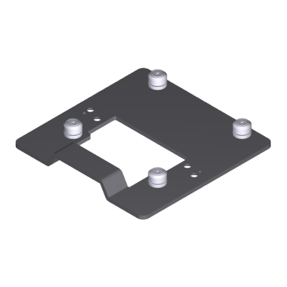
Pole Mount This kit provides a Pole Mount for the NCR CX7 All-in-One POS (7772) or NCR CX5 All-in-One POS (7773) with Remote I/O. Kit Contents... - Page 4 Pole Mount Dimensions Mounting Holes...
-
Page 5: Installation Procedure
Pole Mount Installation Procedure The Quick-Release Bracket is an option to mount the Head. Another option is to mount the Head directly on the hinge of the Pole Mount and the Cable Covers will be used. • With Quick-Release Bracket below •... - Page 6 Pole Mount 3. Disconnect the Cables. a. Loosen the thumbscrew of the 180-degree USB-C Cable then disconnect the Cable. b. Remove the Ethernet Cable from the Cable Management Hook then disconnect the Cable. 4. Loosen the two (2) captive screws that secure the Back Cover to the Display.
- Page 7 Pole Mount 5. Rotate the Back Cover away from the Display and unhook the Back Cover Tabs.
- Page 8 Pole Mount 6. Remove the four (4) screws securing the Display Back Cover to the hinge of the Base.
- Page 9 Pole Mount 7. Install the Back Cover on the Display. a. Insert the Back Cover Tabs into the openings in the back of the Display, then rotate the Back Cover onto the Display. b. Secure the Back Cover with two (2) captive screws.
- Page 10 Pole Mount 8. Connect the Cables on the back of the Display. a. Connect the Ethernet Cable until latched and secure the cable under the Cable Management Hook. b. Connect the 180-degree USB-C Cable and tighten the thumbscrew. 9. Route the Cables through the Bracket and down the Pole.
- Page 11 Pole Mount 10. Install the Display on the Bracket (4 thumbscrews). Without Quick-Release Bracket Warning: Disconnect the AC power cord from the AC outlet and wait 30 seconds before servicing the terminal. 1. Lay the Display face down on a flat surface. Note: Always use a soft material (cloth, foam) to protect the display screen when placing the terminal face down.
- Page 12 Pole Mount b. Rotate and unhook the Cable Cover from the Back Cover. 3. Disconnect the Cables. a. Loosen the thumbscrew of the 180-degree USB-C Cable then disconnect the Cable. b. Remove the Ethernet Cable from the Cable Management Hook then disconnect the Cable.
- Page 13 Pole Mount 4. Loosen the two (2) captive screws that secure the Back Cover to the Display. 5. Rotate the Back Cover away from the Display and unhook the Back Cover Tabs.
- Page 14 Pole Mount 6. Remove the four (4) screws securing the Display Back Cover to the hinge of the Base.
- Page 15 Pole Mount 7. Install the Display Back Cover on the hinge of the Pole (4 screws).
- Page 16 Pole Mount 8. Install the Back Cover and Pole Assembly on the Display. a. Insert the Back Cover Tabs into the openings in the back of the Display, then rotate the Back Cover onto the Display. b. Secure the Back Cover with two (2) captive screws.
- Page 17 Pole Mount 9. Connect the Cables on the back of the Display. a. Connect the Ethernet Cable until latched and secure the cable under the Cable Management Hook. b. Connect the 180-degree USB-C Cable and tighten the thumbscrew. 10. Route the Cables through the Pole.
- Page 18 Pole Mount 11. Install the Cable Cover. a. Hook the bottom of the Cable Cover to the Back Cover, then rotate the Cable Cover into place. b. Secure the Cable Cover with two (2) screws.
- Page 19 Pole Mount 12. Install the Pole on the countertop using four (4) M4 wood screws (one on each corner).